
Related Manuals for HMS Networks Intesis IN771AIR00LO000


Summary of Contents for HMS Networks Intesis IN771AIR00LO000
- Page 1 ENGLISH Panasonic domestic and commercial with KNX, Serial and IP support IN771AIR00LO000 GATEWAY USER MANUAL Version 1.0.1 Publication date 2023-05-14...
- Page 2 The information in this document shall therefore not be construed as a commitment on the part of HMS Networks and is subject to change without notice. HMS Networks makes no commitment to update or keep current the information in this document.
-
Page 3: Table Of Contents
Panasonic domestic and commercial with KNX, Serial and IP support Table of Contents 1. Description and Order Codes ..................... 1 2. Licensing ..........................2 3. General Information ........................ 3 3.1. Intended Use of the User Manual ..................3 3.2. General Safety Information ....................3 3.3. -
Page 4: Description And Order Codes
Description and Order Codes Panasonic domestic and commercial with KNX, Serial and IP support 1. Description and Order Codes IN771AIR00LO000 Gateway Modbus®, KNX®, BACnet®, and Home Automation® gateway for Panasonic® air conditioning systems ORDER CODE LEGACY ORDER CODE IN771AIR00LO000 INBACPAN128O000 INMBSPAN128O000 NOTE The order code may vary depending on the product seller and the buyer's location. -
Page 5: Licensing
Panasonic domestic and commercial with KNX, Serial and IP support Licensing 2. Licensing Distribution license(s) for the IN771AIR00LO000 gateway: Maximum AC units Order Code License Indoor units Outdoor units IN771AIR00LO000 Large NOTE The order code may vary depending on the product seller and the buyer's location. Page 2 of 40 USER MANUAL Version 1.0.1... -
Page 6: General Information
General Information Panasonic domestic and commercial with KNX, Serial and IP support 3. General Information 3.1. Intended Use of the User Manual This manual contains the main features of this Intesis gateway and the instructions for its appropriate installation, configuration, and operation. The contents of this manual should be brought to the attention of any person who installs, configures, or operates this gateway or any associated equipment. - Page 7 Panasonic domestic and commercial with KNX, Serial and IP support Admonition Messages and Symbols NOTE Additional information which may facilitate installation and/or operation. Helpful advice and suggestions. NOTICE Remarkable Information. Page 4 of 40 USER MANUAL Version 1.0.1...
-
Page 8: Overview
Overview Panasonic domestic and commercial with KNX, Serial and IP support 4. Overview This document describes the available applications for this IN771AIR00LO000 gateway. IMPORTANT This document assumes that the user is familiar with these technologies. Figure 1. Integration of Panasonic AC systems into Modbus installations Figure 2. -
Page 9: Inside The Package
Figure 3. Integration of Panasonic AC systems into KNX installations Figure 4. Integration of Panasonic AC systems into Home Automation installations 4.1. Inside the Package Items included: • Intesis IN771AIR00LO000 gateway • USB Mini-B type to USB A type cable • Installation sheet 4.2. Gateway Main Features •... -
Page 10: Gateway General Functionality
Depending on the AC bus, some of these AC connection ports are not used. 4.3. Gateway General Functionality With this Intesis IN771AIR00LO000 gateway, you can easily integrate Panasonic air conditioning (AC) systems into an installation based on Modbus TCP, Modbus RTU, KNX, BACnet/IP, BACnet MS/TP, or Home Automation. To do so, the gateway acts as a server device of the installation itself, accessing all signals from each air conditioner unit and controlling the whole AC network. -
Page 11: Hardware
Panasonic domestic and commercial with KNX, Serial and IP support Hardware 5. Hardware 5.1. Mounting IMPORTANT Before mounting, please ensure that the chosen installation place preserves the gateway from direct solar radiation, water, high relative humidity, or dust. IMPORTANT Maximum mounting height: below 2 meters (6.5 feet). NOTE Mount the gateway on a wall or over a DIN rail. - Page 12 Mounting Panasonic domestic and commercial with KNX, Serial and IP support DIN rail mounting Keep the clips down in their original position. Fit the gateway’s top side clips in the upper edge of the DIN rail. Use a screwdriver or similar to pull the bottom clip down. Fit the low side of the gateway in the DIN rail and let the clip switch back to its original position, locking the gateway to the rail.
-
Page 13: Connection
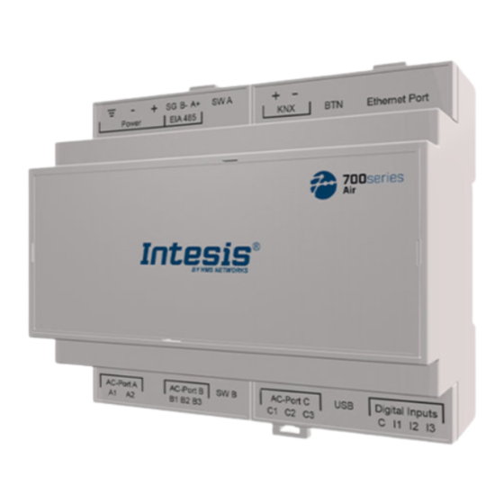
Panasonic domestic and commercial with KNX, Serial and IP support Connection 5.2. Connection CAUTION Disconnect all systems from the power source before manipulating and connecting them to the gateway. 5.2.1. Gateway Connectors Figure 5. General view of all gateway connectors 1. - Page 14 Connection Panasonic domestic and commercial with KNX, Serial and IP support IMPORTANT Use solid or stranded wires (twisted or with ferrule). Wire cross-section/gauge for all wire connectors: • 1 core: 0.5 to 2.5 mm (24 to 11 AWG). • 2 cores: 0.5 to 1.5mm (24 to 15 AWG).
-
Page 15: Common Connections
Panasonic domestic and commercial with KNX, Serial and IP support Connection 5.2.2. Common Connections 5.2.2.1. Connecting the Gateway to the Power Supply The power supply connector is a green pluggable terminal block (3 poles) labeled as Power. IMPORTANT • Use SELV-rated NEC class 2 or limited power source (LPS) power supply. •... -
Page 16: Connection Procedure For Modbus
Connection Panasonic domestic and commercial with KNX, Serial and IP support 5.2.3. Connection Procedure for Modbus NOTE Remember to check the Common Connections (page 12). For Modbus TCP: 1. Connect the Modbus TCP Ethernet cable to the gateway's Ethernet Port. IMPORTANT Use a straight Ethernet UTP/FTP CAT5 or higher cable. - Page 17 Panasonic domestic and commercial with KNX, Serial and IP support Connection 2. Use the supplied USB Mini-B type to A type cable to connect the gateway, through its USB port, to a PC to configure it with Intesis MAPS. NOTE For Modbus RTU only, you can use the Ethernet Port to connect the gateway and the PC instead.
-
Page 18: Connection Procedure For Knx
Connection Panasonic domestic and commercial with KNX, Serial and IP support 5.2.4. Connection Procedure for KNX NOTE Remember to check the Common Connections (page 12). 1. Connect the KNX TP communication cable to the gateway's KNX port. IMPORTANT Observe polarity. 2. -
Page 19: Connection Procedure For Bacnet
Panasonic domestic and commercial with KNX, Serial and IP support Connection 5.2.5. Connection Procedure for BACnet NOTE Remember to check the Common Connections (page 12). For BACnet/IP: 1. Connect the BACnet/IP Ethernet cable to the gateway's Ethernet Port. The correct cable to use depends on where the gateway is connected: •... - Page 20 Connection Panasonic domestic and commercial with KNX, Serial and IP support 2. Use the supplied USB Mini-B type to A type cable to connect the gateway, through its USB port, to a PC to configure it with Intesis MAPS. NOTE For BACnet MS/TP only, you can use the Ethernet Port to connect the gateway and the PC instead.
-
Page 21: Connection Procedure For Home Automation
Panasonic domestic and commercial with KNX, Serial and IP support Connection 5.2.6. Connection Procedure for Home Automation NOTE Remember to check the Common Connections (page 12). 1. Connect the Home Automation Ethernet cable to the gateway's Ethernet Port. IMPORTANT Use a straight Ethernet UTP/FTP CAT5 or higher cable. IMPORTANT If communicating through the LAN of the building, contact the network administrator and make sure traffic on the used port is allowed through all LAN paths. -
Page 22: Led Indicators
LED Indicators Panasonic domestic and commercial with KNX, Serial and IP support 5.3. LED Indicators Figure 6. Gateway layout Color Description Top side LED 1 (PWR) Green Power on (not programmable) LED 2 (ERR) Blinking: Hardware error LED 3 Green 485 Tx (RS485 for BACnet or Modbus) LED 4 Yellow... - Page 23 Panasonic domestic and commercial with KNX, Serial and IP support LED Indicators NOTE LEDs are hidden behind the four frontal labeled covers. These covers are assembled by pressure, so you just need to pull them to remove them. Page 20 of 40 USER MANUAL Version 1.0.1...
-
Page 24: Dip Switches
DIP Switches Panasonic domestic and commercial with KNX, Serial and IP support 5.4. DIP Switches See figure: Gateway layout (page 19) 1: DIP switch A (SW A). 2: DIP switch B (SW B). Each DIP switch is dedicated to a 485 port, and its function is to activate or deactivate the termination resistor and the polarization of each port: Position Description... -
Page 25: Push Button
Panasonic domestic and commercial with KNX, Serial and IP support Push Button 5.5. Push Button Find the push button at the top side, between the KNX and the Ethernet connectors. See Figure Gateway layout (page 19) NOTE The button is hidden and only accessible using a thin object like a paper clip. Common functionality: Reset factory settings Push the button. -
Page 26: Technical Specifications
Technical Specifications Panasonic domestic and commercial with KNX, Serial and IP support 5.6. Technical Specifications Plastic, type PC (UL 94 V-0). Color: Light Grey. RAL 7035 Case Net dimensions (dxwxh): 90x106x58 mm / 3.5x4.2x2.3" Recommended space for installation (dxwxh): 130x115x100 mm / 5.1x4.5x3.9" Wall: M3 25mm (1") length screws. -
Page 27: Dimensions
Panasonic domestic and commercial with KNX, Serial and IP support Dimensions 5.7. Dimensions • Net dimensions (DxWxH) Millimeters: 90 x 106 x 58 mm Inches: 3.5 x 4.2 x 2.3" • Clear space for installation (DxWxH) Millimeters: 130 x 115 x 100 mm Inches: 5.1 x 4.5 x 3.9"... -
Page 28: Available Applications
Available Applications Panasonic domestic and commercial with KNX, Serial and IP support 6. Available Applications 6.1. Integration into Modbus Systems 6.1.1. Modbus Registers NOTICE This part is common for Modbus RTU and TCP. Functions to read Modbus registers: • 03 Read Holding Registers. •... - Page 29 Panasonic domestic and commercial with KNX, Serial and IP support Integration into Modbus Systems Register name Possible values Fan Speed Low (all the units) 1-Set Fan Speed Low Fan Speed Med (all the units) 1-Set Fan Speed Med Fan Speed High (all the units) 1-Set Fan Speed High Vanes Stop (all the units) 1-Set Vanes Stop...
- Page 30 Integration into Modbus Systems Panasonic domestic and commercial with KNX, Serial and IP support Register name Possible values Modbus address formula Unit Error code 0-No Error, n (0 .. 255)-Error (IU address×100)+((L-1)×10000)+19 Filter Alarm 0-Normal, 1-Alarm (IU address×100)+((L-1)×10000)+20 Filter Alarm Reset 1-Reset (IU address×100)+((L-1)×10000)+21 Communication Error IU...
-
Page 31: Integration Into Knx Systems
Panasonic domestic and commercial with KNX, Serial and IP support Integration into KNX Systems 6.2. Integration into KNX Systems 6.2.1. KNX Signals The following tables list all available KNX signals for this gateway. NOTE Physical Address: The gateway supports (P/S) and (P/I/S) format levels. NOTICE Communication object flags: •... - Page 32 Integration into KNX Systems Panasonic domestic and commercial with KNX, Serial and IP support Object name Possible values Flags 0-Auto, 1-Heat, 2-Dry, 3-Fan, 4-Cool, 5-AutoHeat, 6- Status_Operation mode 5.x (1byte) R, T AutoCool Control_Operation mode 0-Cool, 1-Heat, 2-Fan, 3-Dry, 4-Auto 5.x (1byte) 0-Cool, 1-Heat, 2-Fan, 3-Dry, 4-Auto, 5-AutoHeat, 6- Status_Operation mode...
- Page 33 Panasonic domestic and commercial with KNX, Serial and IP support Integration into KNX Systems Object name Possible values Flags 1-Vanes position-4 active, 0-Vanes position-4 not Status_Vanes position-4 1.001-DPT_Switch (1bit) R, T active Control_Vanes position-5 1-Set position-5 vanes 1.001-DPT_Switch (1bit) 1-Vanes position-5 active, 0-Vanes position-5 not Status_Vanes position-5 1.001-DPT_Switch (1bit) R, T...
- Page 34 Integration into KNX Systems Panasonic domestic and commercial with KNX, Serial and IP support NOTE The default unit for the consumption signals is Wh, but you can set it in KWh instead. If so, the DPT number changes from 13.010 to 13.013. USER MANUAL Version 1.0.1 Page 31 of 40...
-
Page 35: Integration Into Bacnet Systems
Panasonic domestic and commercial with KNX, Serial and IP support Integration into BACnet Systems 6.3. Integration into BACnet Systems NOTICE You can see the Protocol Implementation Conformance Statement (PICS) document on https:// www.intesis.com/docs/bacnet-server-pic-statement-771 6.3.1. BACnet Objects NOTICE This part is common for BACnet MS/TP and BACnet/IP. Input object types: •... - Page 36 Integration into BACnet Systems Panasonic domestic and commercial with KNX, Serial and IP support Table 11. Indoor unit signals Object name Possible values Object type Object instance (U[1..64]*100)+ LXOXXUXX_On/Off_S 0-Off, 1-On 3-Binary Input ((L-1)*20000)+0 (U[1..64]*100)+ LXOXXUXX_On/Off_C 0-Off, 1-On 4-Binary Output ((L-1)*20000)+0 1-Heat, 2-Cool, 3-Fan, 4-Dry, 5-Auto, 6- (U[1..64]*100)+...
- Page 37 Panasonic domestic and commercial with KNX, Serial and IP support Integration into BACnet Systems Object name Possible values Object type Object instance (U[1..64]*100)+ LXOXXUXX_Unit Error Code 0-No Error, X-Error (0 .. 255) 0-Analog Input ((L-1)*20000)+14 (U[1..64]*100)+ LXOXXUXX_Filter Sign 0-Normal, 1-Alarm 3-Binary Input ((L-1)*20000)+2 (U[1..64]*100)+...
-
Page 38: Integration Into Home Automation Systems
Integration into Home Automation Systems Panasonic domestic and commercial with KNX, Serial and IP support 6.4. Integration into Home Automation Systems 6.4.1. Home Automation Signals The following tables list all available Home Automation signals for this gateway. NOTE • SET: Command used to control the indoor unit. It is sent by the client. •... -
Page 39: Late Configuration: Change The Gateway's Protocol
Panasonic domestic and commercial with KNX, Serial and IP support Late Configuration: Change the Gateway's Protocol 7. Late Configuration: Change the Gateway's Protocol Reconfiguring the gateway with a different protocol is very easy: Connect the gateway to the PC and open the configuration tool Intesis MAPS. Select the new template you need. -
Page 40: Error Codes
Error Codes Panasonic domestic and commercial with KNX, Serial and IP support 8. Error Codes NOTE These error codes are the same for all applications. Error in Error Code Error category Error Description Control Panel No active error GHP - Engine oil pressure fault GHP - Engine oil level fault GHP - Engine over speed GHP - Engine under speed... - Page 41 Panasonic domestic and commercial with KNX, Serial and IP support Error Codes Error in Error Code Error category Error Description Control Panel Duplicate adaptor address Mix of PAC & GHP type units on adaptor Memory fault in adaptor Incorrect address setting in adaptor Host terminal software failure Host terminal hardware failure Host terminal processing failure...
- Page 42 Error Codes Panasonic domestic and commercial with KNX, Serial and IP support Error in Error Code Error category Error Description Control Panel Indoor Heat Exch freeze temp sensor failure (E2) Indoor Heat Exch outlet temp sensor failure (E3) Outdoor Discharge temp sensor failure (TD) or (DISCH1) Outdoor Discharge temp sensor failure (DISCH2) Outdoor Heat Exch temp sensor failure (C1) or (EXG1) Outdoor Heat Exch temp sensor failure (C2) or (EXL1)
- Page 43 Panasonic domestic and commercial with KNX, Serial and IP support Error Codes Error in Error Code Error category Error Description Control Panel Outdoor unit capacity code not set Group control wiring incorrect Indoor unit type setting error, capacity Indoor unit paring fault Water heat exch unit setting failure Miss-match of outdoor unit with different refrigerant 4-way valve failure...
Need help?
Do you have a question about the Intesis IN771AIR00LO000 and is the answer not in the manual?
Questions and answers