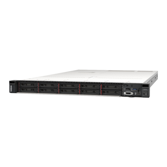
Lenovo ThinkSystem SR645 Maintenance Manual
Hide thumbs
Also See for ThinkSystem SR645:
- Setup manual (188 pages) ,
- System manual (50 pages) ,
- Quick start (2 pages)
Table of Contents
Advertisement
Quick Links
Advertisement
Chapters
Table of Contents

Related Manuals for Lenovo ThinkSystem SR645


Summary of Contents for Lenovo ThinkSystem SR645
- Page 1 ThinkSystem SR645 Maintenance Manual Machine Types: 7D2X and 7D2Y...
- Page 2 Before using this information and the product it supports, be sure to read and understand the safety information and the safety instructions, which are available at: http://thinksystem.lenovofiles.com/help/topic/safety_documentation/pdf_files.html In addition, ensure that you are familiar with the terms and conditions of the Lenovo warranty for your server, which can be found at: http://datacentersupport.lenovo.com/warrantylookup First Edition (June 2020) ©...
-
Page 3: Table Of Contents
10 x 2.5-inch front drive bays (6 SAS/SATA + Remove a hot-swap power supply unit ..150 2 AnyBay + 2 NVMe) ... © Copyright Lenovo 2020... - Page 4 Remove a system fan ... 223 Trademarks ....266 Install a system fan... . 225 ThinkSystem SR645 Maintenance Manual...
- Page 5 Telecommunication regulatory statement ..267 Index ....269 Electronic emission notices ..267 © Copyright Lenovo 2020...
- Page 6 ThinkSystem SR645 Maintenance Manual...
-
Page 7: Safety
Vor der Installation dieses Produkts die Sicherheitshinweise lesen. Prima di installare questo prodotto, leggere le Informazioni sulla Sicurezza. Les sikkerhetsinformasjonen (Safety Information) før du installerer dette produktet. Antes de instalar este produto, leia as Informações sobre Segurança. © Copyright Lenovo 2020... -
Page 8: Safety Inspection Checklist
1 & IEC 60950-1, the standard for Safety of Electronic Equipment within the Field of Audio/Video, Information Technology and Communication Technology. Lenovo assumes you are qualified in the servicing of equipment and trained in recognizing hazards energy levels in products. Access to the equipment is by the use of a tool, lock and key, or other means of security, and is controlled by the authority responsible for the location. - Page 9 Click the Power tab to see all line cords. • Make sure that the insulation is not frayed or worn. 3. Check for any obvious non-Lenovo alterations. Use good judgment as to the safety of any non-Lenovo alterations. 4. Check inside the server for any obvious unsafe conditions, such as metal filings, contamination, water or other liquid, or signs of fire or smoke damage.
- Page 10 ThinkSystem SR645 Maintenance Manual viii...
-
Page 11: Chapter 1. Introduction
Identifying your server When you contact Lenovo for help, the machine type and serial number information helps support technicians to identify your server and provide faster service. The machine type and serial number are on the ID label on the right rack latch in the front of the server. - Page 12 Scan the QR code with a mobile device and a QR code reader application to get quick access to the Lenovo Service Web site for this server. The Lenovo Service Information Web site provides additional information for parts installation and replacement videos, and error codes for server support.
-
Page 13: Specifications
• Designed for Land Grid Array (LGA) 4094 (SP3) socket • Scalable up to 128 cores • Thermal Design Power (TDP): up to 280 watts For a list of supported processors, see: https://static.lenovo.com/us/en/serverproven/index.shtml For technical rules for processors and heat sinks, see Technical rules for processors and heat sinks. - Page 14 Note: The operating speed and total memory capacity depend on the processor model and UEFI settings. For a list of supported memory, see the Lenovo ServerProven Web site: https://static.lenovo.com/us/en/serverproven/index.shtml For technical rules for memory modules, see Technical rules for DIMMs.
- Page 15 Table 1. Server specifications (continued) Specification Description Input/Output (I/O) features • Front: – One VGA connector (optional) – One USB 2.0 connector – One USB 3.1 Gen 1 connector – One external diagnostics connector – One diagnostics panel (optional) – One LCD diagnostics panel (optional) •...
- Page 16 • These sound power levels are measured in controlled acoustical environments according to procedures specified by ISO 7779 and are reported in accordance with ISO 9296. • The declared acoustic noise levels are based on specified configurations, which may change slightly depending on configuration/conditions. ThinkSystem SR645 Maintenance Manual...
- Page 17 Table 1. Server specifications (continued) Specification Description Electrical input One or two hot-swap power supplies for redundancy support: Table 2. Electrical input for power supplies Power supply 100–127 V 200–240 V 240 V dc -48 V dc 500-watt 80 PLUS √...
-
Page 18: Firmware Updates
Machine-type-specific firmware-only UXSPs are also available. See the following table to determine the best Lenovo tool to use for installing and setting up the firmware: Note: The server UEFI settings for option ROM must be set to Auto or UEFI to update firmware using Lenovo XClarity Essentials. - Page 19 Additional information about using Lenovo XClarity Provisioning Manager V3 to update firmware is available at: http://sysmgt.lenovofiles.com/help/topic/LXPMv3/LXPMv3_platform_update.html • Lenovo XClarity Controller If you need to install a specific update, you can use the Lenovo XClarity Controller interface for a specific server. Chapter 1 Introduction...
- Page 20 – If you update firmware through the Lenovo XClarity Controller, make sure that you have downloaded and installed the latest device drivers for the operating system that is running on the server. – Specific details about updating firmware using Lenovo XClarity Controller are available at: http://sysmgt.lenovofiles.com/help/topic/com.lenovo.systems.management.xcc.doc/NN1ia_c_...
-
Page 21: Tech Tips
Tech Tips Lenovo continually updates the support website with the latest tips and techniques that you can use to solve issues that your server might encounter. These Tech Tips (also called retain tips or service bulletins) provide procedures to work around issues or solve problems related to the operation of your server. -
Page 22: Power On The Server
To place the server in a standby state (power status LED flashes once per second): Note: The Lenovo XClarity Controller can place the server in a standby state as an automatic response to a critical system failure. -
Page 23: Chapter 2. Server Components
• Server models with eight 2.5-inch front drive bays (backplane-less) • Server models with ten 2.5-inch front drive bays (backplane-less) • Server models with four 3.5-inch front drive bays (backplane-less) • Server models with eight 2.5-inch front drive bays (with LCD diagnostics panel) © Copyright Lenovo 2020... - Page 24 External diagnostics connector XClarity Controller USB connector VGA connector (optional) Rack latch (right) Pull-out information tab Drive bay filler (1) Drive bays (4) Rack latch (left) Note: For more information about each component, see Front components overview. ThinkSystem SR645 Maintenance Manual...
- Page 25 Server model with eight 2.5-inch drive bays Table 4. Components on the front of the server Callout Callout Drive status LED Drive activity LED Drive bay filler (1) Diagnostics panel External diagnostics connector USB 3.1 Gen 1 connector XClarity Controller USB connector VGA connector (optional) Rack latch (right) Pull-out information tab...
- Page 26 USB 3.1 Gen 1 connector External diagnostics connector XClarity Controller USB connector VGA connector (optional) Rack latch (right) Pull-out information tab Drive bays (10) Rack latch (left) Note: For more information about each component, see Front components overview. ThinkSystem SR645 Maintenance Manual...
- Page 27 Server model with four 3.5-inch drive bays Table 6. Components on the front of the server Callout Callout Rack latch (right) VGA connector (optional) External diagnostics connector XClarity Controller USB connector and USB 3.1 Gen 1 connector Diagnostics panel Rack latch (left) Pull-out information tab Drive bays (4) Drive status LED...
- Page 28 External diagnostics connector XClarity Controller USB connector VGA connector (optional) Rack latch (right) Pull-out information tab Drive bay filler (1) Drive bay fillers (4) Rack latch (left) Note: For more information about each component, see Front components overview. ThinkSystem SR645 Maintenance Manual...
- Page 29 Server model with eight 2.5-inch drive bays (backplane–less) Table 8. Components on the front of the server Callout Callout Diagnostics panel Drive bay filler (1) USB 3.1 Gen 1 connector External diagnostics connector XClarity Controller USB connector VGA connector (optional) Pull-out information tab Rack latch (right) Drive bay filler (8)
- Page 30 USB 3.1 Gen 1 connector External diagnostics connector (Reserved) XClarity Controller USB connector VGA connector (optional) Rack latch (right) Pull-out information tab Drive bay fillers (2+2) Rack latch (left) Note: For more information about each component, see Front components overview. ThinkSystem SR645 Maintenance Manual...
- Page 31 Server model with four 3.5-inch drive bays (backplane-less) Table 10. Components on the front of the server Callout Callout Rack latch (right) VGA connector (optional) External diagnostics connector XClarity Controller USB connector and USB 3.1 Gen 1 connector Diagnostics panel Rack latch (left) Pull-out information tab Drive bay fillers (4)
-
Page 32: External Diagnostics Connector
USB 3.1 Gen 1 connector External diagnostics connector XClarity Controller USB connector VGA connector (optional) Rack latch (right) Pull-out information tab Drive bays (8) Rack latch (left) Note: For more information about each component, see Front components overview. ThinkSystem SR645 Maintenance Manual... - Page 33 Front components overview Diagnostics panel The diagnostics panel is integrated in front I/O assembly on some models. For information about the controls and status LEDs on the diagnostics panel, see Diagnostics panel. Drive LEDs Each hot-swap drive comes with an activity LED and status LED and the signals are controlled by the backplanes.
-
Page 34: Usb 3.1 Gen 1 Connector
Pull-out information tab The Lenovo XClarity Controller network access label is attached on the pull-out information tab. The default Lenovo XClarity Controller hostname and the IPv6 Link Local Address (LLA) are provided on the tab. Rack latches If your server is installed in a rack, you can use the rack latches to help you slide the server out of the rack. -
Page 35: Diagnostics Panel
Diagnostics panel The diagnostics panel provides controls, connectors, and LEDs. Note: Diagnostics panel with an LCD display is available for some models. For details, see LCD diagnostics panel/handset. Figure 5. Diagnostics panel Power button with power status LED You can press the power button to power on the server when you finish setting up the server. You also can hold the power button for several seconds to power off the server if you cannot shut down the server from the operating system. - Page 36 Each time you press the system ID button, the state of both the system ID LEDs changes. The LEDs can be changed to on, blinking, or off. You can also use the Lenovo XClarity Controller or a remote management program to change the state of the system ID LEDs to assist in visually locating the server among other servers.
-
Page 37: Lcd Diagnostics Panel/Handset
LCD diagnostics panel/handset The LCD diagnostics panel is a component attached to the front of the server, the external LCD diagnostics handset is an external device that can be connected to the server with a cable. Functions of the integrated component and the external device are the same, both of them can be used to quickly access system information such as active errors, system status, firmware, network information, and health information. - Page 38 Note: Pay attention to the following steps when unplugging the external handset: Step 1. Press the plastic clip on the plug in the shown direction. Step 2. Gently pull out the cable from the connector while keeping the clip pressed down. ThinkSystem SR645 Maintenance Manual...
- Page 39 Display panel overview Both the integrated panel and the external handset consist of an LCD display and 5 navigation buttons. LCD display Scroll buttons (up/down/left/right). Press the scroll buttons to locate and select system information. Select button. Press the select button to select from the menu options. Chapter 2 Server components...
- Page 40 Options flow diagram The LCD diagnostics panel/handset shows various system information. Navigate through the options with the scroll keys. ThinkSystem SR645 Maintenance Manual...
- Page 41 Full menu list Following is the list of options available on the LCD diagnostics panel/handset. Switch between an option and the subordinate information entries with the select button, and switch among options or information entries with the scroll buttons. Home Menu (System Status Dashboard) Home Menu Example System name...
- Page 42 • Static IPv6 IP IPv4 Network Mask • Current IPv6 Gateway :x.x.x.x IPv4 Default Gateway • IPv6 DNS : x.x.x.x Note: Only the MAC address that is currently in use is displayed (extension or shared). ThinkSystem SR645 Maintenance Manual...
- Page 43 System Environmental Information Sub Menu Example Ambient Temp: 24 C Exhaust Temp: 30 C • Ambient temperature PSU1: Vin= 213 w Inlet= 26 C • Exhaust temperature • PSU status FAN1 Front: 21000 RPM • Spinning speed of fans by RPM FAN2 Front: 21000 RPM FAN3 Front:...
-
Page 44: Rear View
• Server model with three PCIe slots • Server model with two PCIe slots • Server model with two hot-swap 2.5-inch rear drive bays and one PCIe slot • Server model with two hot-swap 7mm rear drive bays and two PCIe slots ThinkSystem SR645 Maintenance Manual... - Page 45 Server model with three PCIe slots The following illustration shows the rear view of server model with three PCIe slots. Depending on the model, your server might look slightly different from the illustration below. Table 12. Components on the rear of the server Callout Callout PCIe slot 1 on riser 1 assembly...
- Page 46 USB 3.1 Gen 1 connectors (3) VGA connector XClarity Controller network connector Ethernet connectors on OCP 3.0 Ethernet adapter (optional, two or four connectors may be available) Note: For more information about each component, see Rear components overview. ThinkSystem SR645 Maintenance Manual...
- Page 47 Server model with two 2.5-inch hot-swap rear drive bays and one PCIe slot The following illustration shows the rear view of the server model with two hot-swap drive bays and one PCIe slot. Depending on the model, your server might look slightly different from the illustration below. Table 14.
- Page 48 USB 3.1 Gen 1 connectors (3) VGA connector XClarity Controller network connector Ethernet connectors on OCP 3.0 Ethernet adapter (optional, two or four connectors may be available) Note: For more information about each component, see Rear components overview. ThinkSystem SR645 Maintenance Manual...
-
Page 49: Nmi Button
Rear components overview Drive LEDs Each hot-swap drive comes with an activity LED and status LED and the signals are controlled by the backplanes. Different colors and speeds indicate different activities or status of the drive. The following illustration shows the LEDs on a Hard disk drive or solid–state drive. Figure 6. -
Page 50: Vga Connector
The hot-swap redundant power supply helps you avoid significant interruption to the operation of the system when a power supply fails. You can purchase a power supply option from Lenovo and install the power supply to provide power redundancy without turning off the server. -
Page 51: Rear View Leds
Rear view LEDs The rear of the server provides system ID LED, system error LED, Ethernet LEDs, and power supply LEDs. Server rear view LEDs The following illustration shows the LEDs on the rear view of server model with two PCIe slots. The LEDs on the rear view of other server models are the same. - Page 52 Each time you press the system ID button, the state of both the system ID LEDs changes. The LEDs can be changed to on, blinking, or off. You can also use the Lenovo XClarity Controller or a remote management program to change the state of the system ID LEDs to assist in visually locating the server among other servers.
-
Page 53: System Board Components
System board components The illustration in this section shows the component locations on the system board. Figure 8. System board components NMI Button System Board Release Pin Serial Port Module Connector CMOS Battery (CR2032) Internal USB Connector Riser 1 slot OCP 3.0 Network Card Connector TPM Module Connector Chapter 2... - Page 54 PCIe Connector 5 Power Supply 1 Connector PCIe Connector 7 PCIe Connector 8 Power Supply 2 Connector Internal Raid Power Connector PCIe Connector 6 PCIe Connector 9 (Reserved) PCIe Connector 10 (Reserved) PCIe Connector 2 Riser 2 slot ThinkSystem SR645 Maintenance Manual...
-
Page 55: System Board Leds
System board LEDs The illustration in this section shows the LEDs on the system board. Figure 9. System board LEDs Table 17. LEDs on the system board Callout Callout System error LED System ID LED DIMM error LEDs (32) Fan error LEDs (8) FPGA error LED FPGA heart beat LED FPGA power LED... - Page 56 BMC heart beat LED The BMC heart beat LED helps you identify the BMC status. Status Color Description Green The BMC is not alive. Blinking Green The BMC is alive. None The BMC is not alive. ThinkSystem SR645 Maintenance Manual...
- Page 57 Chapter 2 Server components...
-
Page 58: Switch Block And Jumper
• If there is a clear protective sticker on the top of the switch blocks, you must remove and discard it to access the switches. • Any system-board switch or jumper block that is not shown in the illustrations in this document is reserved. Figure 10. Switch block and jumper locations on system board ThinkSystem SR645 Maintenance Manual... - Page 59 Table 18. Switch block and jumper description Switch/jumper name Switch/jumper number Description Switch 1 block • Switch 1: One-time power-on password bypass – Toggle to ON or OFF to bypass the power-on password for one time. Note: The switch cannot skip the privilege administrator password.
-
Page 60: Parts List
Use the parts list to identify each of the components that are available for your server. For more information about ordering the parts shown in Server components: https://datacentersupport.lenovo.com/products/servers/thinksystem/sr645/7d2x/parts Note: Depending on the model, your server might look slightly different from the illustration. ThinkSystem SR645 Maintenance Manual... - Page 61 Figure 11. Server components Chapter 2 Server components...
- Page 62 Tier 1 CRU at your request with no service agreement, you will be charged for the installation. • Tier 2 customer replaceable unit: You may install a Tier 2 CRU yourself or request Lenovo to install it, at no additional charge, under the type of warranty service that is designated for your server.
- Page 63 Table 19. Parts listing (continued) Consumable Description Index Tier 1 CRU Tier 2 CRU Structural parts 2 x 3 2.5-inch drive bay filler √ 2.5-inch drive √ 3.5-inch drive √ 7 mm drive assembly (cage √ +backplanes) 7mm drive √ 7mm drive bay filler √...
-
Page 64: Power Cords
The cord set should have the appropriate safety approvals for the country in which the equipment will be installed. • Power cords for a specific country or region are usually available only in that country or region. ThinkSystem SR645 Maintenance Manual... -
Page 65: Chapter 3. Internal Cable Routing
Use these identifiers to connect the cables to the correct connectors. • Ensure that the relevant cables pass through the cable clips. Cable Route holder Route to BP Pwr connector, Raid Pwr connector, and PCIe connectors (4, 5, 7, 8) 1 3 4 © Copyright Lenovo 2020... - Page 66 Route to intrusion switch cable Route to FIO connector, LCD external connector, M.2 Pwr connector, VGA 2 connector, Front USB 5 6 7 connector, PCIe connectors (1–3, 6, 9, 10), and Raid/HBA connectors ThinkSystem SR645 Maintenance Manual...
- Page 67 Note: Disengage all latches, release tabs, or locks on cable connectors when you disconnect cables from the system board. Failing to release them before removing the cables will damage the cable sockets on the system board, which are fragile. Any damage to the cable sockets might require replacing the system board. Chapter 3 Internal cable routing...
-
Page 68: Cff Rair/Hba Adapter Cabling Routing
Note: The illustration only involves power cable routing, for signal cable routing of CFF RAID/HBA adapters, see 2.5-inch/3.5-inch drive backplane (signal) From Power connector on the CFF RAID/HBA adapter CFF RAID connector on the system board ThinkSystem SR645 Maintenance Manual... -
Page 69: Fio Cable Routing
FIO cable routing Use the section to understand the cable routing for FIO. Cable routing for FIO Note: The illustration shows the cabling scenario for server models with four 3.5-inch front drive bays. Location of each connector on the front of the server varies by models. For detailed location of front I/O components for different models, see Front view. -
Page 70: Intrusion Switch Cable Routing
Intrusion switch cable routing Use the section to understand the cable routing for the intrusion switch. Figure 13. Intrusion switch cable routing From Intrusion switch cable on the fan cage Intrusion switch connector on the system board ThinkSystem SR645 Maintenance Manual... -
Page 71: Super Capacitor Cable Routing
Super capacitor cable routing Use the section to understand the cable routing for backplanes. RAID super capacitor module location Super capacitor on the chassis Super capacitors in the air baffle Super capacitors in riser 3 assembly Chapter 3 Internal cable routing... - Page 72 Figure 14. Power cable routing for super capacitor Note: The super capacitor cable can either be long or short. Refer to Super capacitor installation rules for more information. ThinkSystem SR645 Maintenance Manual...
-
Page 73: 7Mm Drive Backplane Cable Routing
7mm drive backplane cable routing (power & signal) This section provides cable routing information for the 7mm drives. Figure 15. Cable routing for 7mm drives From 7mm signal cable PCIe connector 5 on the system board Power cable 7mm power connector on riser 1 assembly Chapter 3 Internal cable routing... -
Page 74: Drive Backplane Cable Routing
– Server models with 10 x 2.5-inch front drive bays (8AnyBay+2NVMe) Figure 16. Cable routing for M.2 drives From Power cable M.2 power connector on the system board M.2 signal cable PCIe connector 1 on the system board ThinkSystem SR645 Maintenance Manual... -
Page 75: Inch/3.5-Inch Drive Backplane (Power)
2.5-inch/3.5-inch drive backplane (power) Use the section to understand the power cable routing for 2.5-inch or 3.5-inch drive backplanes. Power cable routing for 2.5-inch or 3.5-inch drive backplanes From Power connector on the front drive backplane BP power connector on the system board Power connector on the rear drive backplane Power connector on riser card on riser 1 assembly Chapter 3... -
Page 76: Inch/3.5-Inch Drive Backplane (Signal)
10 x 2.5-inch front drive bays (8AnyBay + 2NVMe) • 10 x 2.5-inch front drive bays (6SAS/SATA + 4AnyBay) • 10 x 2.5-inch front drive bays (6SAS/SATA + 4NVMe) • 10 x 2.5-inch front drive bays (6 SAS/SATA + 2 AnyBay + 2 NVMe) ThinkSystem SR645 Maintenance Manual... -
Page 77: X 2.5-Inch Front Drive Bays (Sas/Sata)
4 x 2.5-inch front drive bays (SAS/SATA) The server model is configured with one 4 x 2.5-inch SAS/SATA front drive backplane. Below lists all supported configurations with this front drive backplane. Storage controller Configuration option Qty. Type Config. 1 Config. 2 SFF 8i RAID/HBA Depending on your server configurations, refer to one of the following sections for cable routing information. -
Page 78: X 2.5-Inch Front Drive Bays (Sas/Sata)
Depending on your server configurations, refer to one of the following sections for cable routing information. • Configuration 1, 2, and 3: front drive bays only • Configuration 4, 5, and 6: front drive bays and rear drive bays ThinkSystem SR645 Maintenance Manual... - Page 79 Configuration 1, 2, and 3: (front drive bays only) Storage controller Con- System board Front BP fig. SFF 8i RAID/HBA CFF 16i RAID/HBA SAS 0 PCIe 2 SAS 1 PCIe 4 Gen 4: C 0 SAS 0, SAS 1 Gen 3: C 0, C 1 SAS 0 SAS 1 PCIe 8...
- Page 80 The following illustration shows the cable routing for the configuration 6, the routing for configuration 4 and 5 ↔ ↔ ↔ ↔ is similar. Connections between connectors: , ... Figure 19. Cable routing for configuration 6 ThinkSystem SR645 Maintenance Manual...
-
Page 81: X 3.5-Inch Front Drive Bays (Sas/Sata)
4 x 3.5-inch front drive bays (SAS/SATA) The server model is configured with one 4 x 3.5-inch SAS/SATA front drive backplane. Below lists all supported configurations with this front drive backplane. Storage controller Rear BP Configuration option Qty. Type Qty. Type Config. - Page 82 Note: For models that support Gen 3 and Gen4 adapters at the same slot, the illustration shows only the cable routing information for Gen 4 adapters, the routing and connector information is similar for Gen 3 adapters. Figure 20. Cable routing for configuration 2 ThinkSystem SR645 Maintenance Manual...
- Page 83 Configuration 3 and 4: (front drive bays and rear drive bays) Front: one 4 x 3.5-inch SAS/SATA backplane Rear: one 2 x 2.5-inch SAS/SATA backplane Storage controller Config. System board Front BP Rear BP SFF 8i RAID/HBA PCIe 2 PCIe 5 Gen 4: C 0 Gen 3: C 0, C 1 The following illustration shows the cable routing for the configuration 4, the routing for configuration 3 is...
- Page 84 Note: For models that support Gen 3 and Gen4 adapters at the same slot, the illustration shows only the cable routing information for Gen 4 adapters, the routing and connector information is similar for Gen 3 adapters. Figure 22. Cable routing for configuration 5 ThinkSystem SR645 Maintenance Manual...
-
Page 85: X 3.5-Inch Front Drive Bays (Anybay)
4 x 3.5-inch front drive bays (AnyBay) The server model is configured with one 4 x 3.5-inch AnyBay front drive backplane. Below lists all supported configurations with this front drive backplane. Storage controller Rear BP Configuration option Qty. Type Qty. Type Config. - Page 86 Note: For models that support Gen 3 and Gen4 adapters at the same slot, the illustration shows only the cable routing information for Gen 4 adapters, the routing and connector information is similar for Gen 3 adapters. Figure 23. Cable routing for configuration 2 ThinkSystem SR645 Maintenance Manual...
- Page 87 Configuration 3 and 4: (front drive bays and rear drive bays) Front: one 4 x 3.5-inch AnyBay backplane Rear: one 2 x 2.5-inch SAS/SATA backplane Storage controller Con- System board Front BP Rear BP fig. SFF 8i RAID/HBA NVMe 0–1 PCIe 3 NVMe 2–3 PCIe 7...
- Page 88 Note: For models that support Gen 3 and Gen4 adapters at the same slot, the illustration shows only the cable routing information for Gen 4 adapters, the routing and connector information is similar for Gen 3 adapters. Figure 25. Cable routing for configuration 6 ThinkSystem SR645 Maintenance Manual...
-
Page 89: 10 X 2.5-Inch Front Drive Bays (Anybay)
10 x 2.5-inch front drive bays (AnyBay) The server model is configured with one 10 x 2.5-inch AnyBay front drive backplane. Below lists all supported configurations with this front drive backplane. Storage controller Front BP Rear BP Configu- ration Onboard Qty. - Page 90 The following illustration shows the cable routing for the configuration 1, the routing for configuration 2 is ↔ ↔ ↔ ↔ similar. Connections between connectors: , ... Figure 26. Cable routing for configuration 1 ThinkSystem SR645 Maintenance Manual...
-
Page 91: 10 X 2.5-Inch Front Drive Bays (Nvme)
10 x 2.5-inch front drive bays (NVMe) The server model is configured with one 10 x 2.5-inch AnyBay front drive backplane. Below lists all supported configurations with this front drive backplane. Note: The AnyBay backplane is used as a pure NVMe backplane. Rear BP Configuration options Qty. - Page 92 The following illustration shows the cable routing for the configuration 1, the routing for configuration 2 is similar. ↔ ↔ ↔ ↔ Connections between connectors: , ... Figure 27. Cable routing for configuration 2 ThinkSystem SR645 Maintenance Manual...
- Page 93 Chapter 3 Internal cable routing...
-
Page 94: 2Nvme)
NVMe 0-1 PCIe 1, PCIe 2 NVMe 2-3 PCIe 3 NVMe 4-5 PCIe 7 NVMe 6-7 PCIe 8 NVMe 8-9 PCIe 6 Gen 4: C 0 SAS 0, SAS 1 Gen 3: C 0, C 1 ThinkSystem SR645 Maintenance Manual... - Page 95 The following illustration shows the cable routing for the configuration 2, the routing for configuration 1 is ↔ ↔ ↔ ↔ similar. Connections between connectors: , ... Note: For models that support Gen 3 and Gen4 adapters at the same slot, the illustration shows only the cable routing information for Gen 4 adapters, the routing and connector information is similar for Gen 3 adapters.
-
Page 96: 4Anybay)
Depending on your server configurations, refer to one of the following sections for cable routing information. • Configuration 1, 2, and 3: front drive bays only • Configuration 4 and 5: front drive bays and rear drive bays ThinkSystem SR645 Maintenance Manual... - Page 97 Configuration 1, 2, and 3: (front drive bays only) Storage controller Con- System board Front BP fig. SFF 16i RAID/HBA CFF 16i RAID/HBA NVMe 0-1 PCIe 3 NVMe 2–3 PCIe 7 SAS 0 PCIe 2 SAS 1 PCIe 4 SAS 2 PCIe 5 NVMe 0–1 PCIe 3...
- Page 98 Figure 29. Cable routing for configuration 2 ThinkSystem SR645 Maintenance Manual...
- Page 99 Configurations 4 and 5: (front drive bays and rear drive bays) Storage controller Config. System board Front BP Rear BP CFF 16i RAID/HBA NVMe 0-1 PCIe 3 NVMe 2–3 PCIe 7 SAS 0 PCIe 2 SAS 1 PCIe 4 SAS 2 PCIe 5 NVMe 0–1 PCIe 3...
-
Page 100: 4Nvme)
Config. 1 2 x 2.5" SAS/SATA Cable routing information for configuration 1 Config. System board Front BP Rear BP NVMe 0-1 PCIe 3 NVMe 2–3 PCIe 7 SAS 0 PCIe 2 SAS 1 PCIe 4 PCIe 5 ThinkSystem SR645 Maintenance Manual... - Page 101 The following illustration shows the cable routing for the configuration 1. Connections between connectors: ↔ ↔ ↔ ↔ , ... Figure 31. Cable routing for configuration 1 Chapter 3 Internal cable routing...
-
Page 102: 10 X 2.5-Inch Front Drive Bays (6 Sas/Sata + 2 Anybay + 2 Nvme)
NVMe 0–1 PCIe 3 NVMe 2–3 PCIe 7 Gen 4: C 0 SAS 0, SAS 1 Gen 3: C 0, C 1 NVMe 0–1 PCIe 3 NVMe 2–3 PCIe 7 SAS 0 SAS 1 PCIe 8 ThinkSystem SR645 Maintenance Manual... - Page 103 The following illustration shows the cable routing for the configuration 3, the routing for configurations 1 and ↔ ↔ ↔ ↔ 2 is similar. Connections between connectors: , ... Note: For models that support Gen 3 and Gen4 adapters at the same slot, the illustration shows only the cable routing information for Gen 4 adapters, the routing and connector information is similar for Gen 3 adapters.
- Page 104 ThinkSystem SR645 Maintenance Manual...
-
Page 105: Chapter 4. Hardware Replacement Procedures
Go to to download firmware updates for your server. ThinkSystem SR645 Drivers and Software Important: Some cluster solutions require specific code levels or coordinated code updates. If the component is part of a cluster solution, verify that the latest level of code is supported for the cluster solution before you update the code. -
Page 106: System Reliability Guidelines
• Remove items from your shirt pocket, such as pens and pencils, in case they fall into the server as you lean over it. • Avoid dropping any metallic objects, such as paper clips, hairpins, and screws, into the server. ThinkSystem SR645 Maintenance Manual... -
Page 107: Handling Static-Sensitive Devices
Handling static-sensitive devices Review these guidelines before you handle static-sensitive devices to reduce the possibility of damage from electrostatic discharge. Attention: Prevent exposure to static electricity, which might lead to system halt and loss of data, by keeping static-sensitive components in their static-protective packages until installation, and handling these devices with an electrostatic-discharge wrist strap or other grounding system. -
Page 108: Technical Rules
280W Quantity 1. Standard fans are enough for low-wattage processors while you can still use performance fans for better cooling. 2. Two fan dummies (fan cages 7 and 8) are required when one processor is installed. ThinkSystem SR645 Maintenance Manual... -
Page 109: Drive Bay Configurations And Requirements
• Up to two 2.5-inch SAS/SATA or two 7mm SAS/SATA rear drives • Up to two M.2 SATA/NVMe drives For a list of supported drives, see: https://static.lenovo.com/us/en/serverproven/index.shtml Drive bay combinations The following table shows the supported drive bay combinations for the chassis with 3.5-inch/2.5-inch front drive bays. - Page 110 – Drive capacity priority: the lowest capacity first – RAID arrays are not support for NVMe SSD drives. – RAID arrays are not support for AIC(all-in-card) SSD drives. – RAID arrays are not support for SED or FIPS HDD/SSD drives. ThinkSystem SR645 Maintenance Manual...
-
Page 111: Technical Rules For Dimms
• Type (depending on the model): TruDDR4 3200, dual-rank, 16 GB/32 GB/64 GB RDIMM For a list of supported memory options, see: https://static.lenovo.com/us/en/serverproven/index.shtml Note: The operating speed and total memory capacity depend on the processor model and UEFI settings. The following figure and table help you locate the memory slots and channels on the system board. - Page 112 DRAM based DIMMs can be mixed, but not in the same channel. • Type: DIMMs of different base module types can be mixed, but not in the same channel. • Vendor: DIMMs from different vendors can be mixed in the same channel. ThinkSystem SR645 Maintenance Manual...
-
Page 113: Technical Rules For Pcie Adapters
Technical rules for PCIe adapters Understanding Type of PCIe adapters supported for different models Server models Supported types and slot location Server models with Riser 1 assembly three PCIe slots • Slot 1: PCIe x16 (x8, x4, x1), low-profile • Slot 2: PCIe x16 (x8, x4, x1), low-profile Riser 2 assembly •... - Page 114 – Short cable: for CFF 2.5'' chassis 1---> 2--- RAID/HBA front chassis >3 Server Super cap 1 in an low- Super cap 1 and 2 on Long cable models with profile riser cage front chassis 3.5'' chassis ThinkSystem SR645 Maintenance Manual...
-
Page 115: Technical Rules For Gpu Adapters
Technical rules for GPU adapters Understanding the technical rules helps you choose the correct GPUs and install them in the supported slots based on what is configured for your server. The following are installation rules for installing GPUs for your server: •... - Page 116 • When 225W or 240W processors are installed, the models support up to two Tesla T4 GPUs under an amb more than 35°(95°F). GPU adapters: 4 x 2.5'' models The only supported processors are 280W processors. The models support up to three Tesla T4 GPUs under of no more than 35°(95°F). ThinkSystem SR645 Maintenance Manual...
-
Page 117: Air Baffle Replacement
Air baffle replacement Use this information to remove and install the air baffle. Note: Air baffle is unavailable when performance heat sink is installed. Remove the air baffle Use this information to remove the air baffle. About this task Depending on the model, your server might not have an air baffle installed. The air baffle you want to remove might be different from the following illustrations, but the removal method is the same. - Page 118 If you would like to reuse the RAID super capacitor module installed on the bottom of the air baffle, remove it from the air baffle. See Remove the RAID super capacitor module on the air baffle. ThinkSystem SR645 Maintenance Manual...
-
Page 119: Install The Air Baffle
Install the air baffle Use this information to install the air baffle. About this task Depending on the model, your server might not have an air baffle installed. The air baffle you want to install might be different from the following illustrations, but the removal method is the same. S033 CAUTION: Hazardous energy present. - Page 120 1. If there is a RAID super capacitor module installed on the bottom of the air baffle, connect it to the RAID adapter with the extension cable that comes with the RAID super capacitor module. 2. Complete the parts replacement. See Complete the parts replacement. ThinkSystem SR645 Maintenance Manual...
-
Page 121: Cmos Battery Replacement
The following tips describe information that you must consider when removing the CMOS battery. • Lenovo has designed this product with your safety in mind. The lithium CMOS battery must be handled correctly to avoid possible danger. If you replace the CMOS battery, you must adhere to the following instructions. - Page 122 Any damage to the socket might require replacing the system board. • Do not tilt or push the CMOS battery by using excessive force. Figure 36. CMOS battery removal After you finish 1. Install a new one. See Install the CMOS battery. ThinkSystem SR645 Maintenance Manual...
- Page 123 2. Dispose of the CMOS battery as required by local ordinances or regulations. Chapter 4 Hardware replacement procedures...
-
Page 124: Install The Cmos Battery
The following tips describe information that you must consider when installing the CMOS battery. • Lenovo has designed this product with your safety in mind. The lithium battery must be handled correctly to avoid possible danger. If you install the CMOS battery, you must adhere to the following instructions. - Page 125 • Read Installation Guidelines to ensure that you work safely. • Power off the server and disconnect all power cords for this task. • Prevent exposure to static electricity, which might lead to system halt and loss of data, by keeping static- sensitive components in their static-protective packages until installation, and handling these devices with an electrostatic-discharge wrist strap or other grounding system.
-
Page 126: Front I/O Assembly Replacement
• eight 2.5-inch front drive bays (1) For server models with four 3.5-inch front drive Front I/O assembly with diagnostics panel (top) bays. For server models with eight 2.5-inch front drive Front I/O assembly+ LCD diagnostics panel assembly bays (2) ThinkSystem SR645 Maintenance Manual... -
Page 127: Remove The Front I/O Assembly
Remove the front I/O assembly Use this information to remove the front I/O assembly. About this task The following illustrates how to remove the front I/O assembly with diagnostics panel. You can remove other front I/O assemblies in the same way. Attention: •... -
Page 128: Install The Front I/O Assembly
Install the screws to secure the front I/O assembly in place. After you finish 1. Connect the front I/O cables to the system board. For detailed cable routing information, see Internal cable routing. 2. Complete the parts replacement. See Complete the parts replacement. ThinkSystem SR645 Maintenance Manual... - Page 129 Chapter 4 Hardware replacement procedures...
-
Page 130: Remove The Lcd Diagnostics Panel
1. Install a new LCD diagnostics panel assembly or filler. See Install the LCD diagnostics panel assembly. 2. If you are instructed to return the old LCD diagnostics panel assembly, follow all packaging instructions and use any packaging materials that are provided. ThinkSystem SR645 Maintenance Manual... -
Page 131: Install The Lcd Diagnostics Panel
Install the LCD diagnostics panel assembly Use this information to install the diagnostics panel assembly. About this task Attention: • Read Installation Guidelines to ensure that you work safely. • Power off the server and disconnect all power cords for this task. •... - Page 132 Slide the diagnostics panel assembly into the front chassis as shown. Ensure that it is seated in place. Figure 42. Diagnostics panel assembly installation After you finish Complete the parts replacement. See Complete the parts replacement. ThinkSystem SR645 Maintenance Manual...
-
Page 133: Hot-Swap Drive Replacement
Hot-swap drive replacement Use this information to remove and install a hot-swap drive. You can remove or install a hot-swap drive without turning off the server, which helps you avoid significant interruption to the operation of the system. Notes: • The term “hot-swap drive” refers to all the supported types of hot-swap hard disk drives, hot-swap solid- state drives, and hot-swap NVMe drives. - Page 134 1. Install the drive filler or a new drive to cover the drive bay. See Install a hot-swap drive. 2. If you are instructed to return the old hot-swap drive, follow all packaging instructions and use any packaging materials that are provided. ThinkSystem SR645 Maintenance Manual...
-
Page 135: Install A Hot-Swap Drive
Install a hot-swap drive Use this information to install a hot-swap drive. About this task Attention: • Read Installation Guidelines to ensure that you work safely. • Prevent exposure to static electricity, which might lead to system halt and loss of data, by keeping static- sensitive components in their static-protective packages until installation, and handling these devices with an electrostatic-discharge wrist strap or other grounding system. - Page 136 Continue to install additional hot-swap drives if necessary. After you finish 1. Reinstall the security bezel if you have removed it. See Install the security bezel. 2. Use the Lenovo XClarity Provisioning Manager V3 to configure the RAID if necessary. For more information, see: https://sysmgt.lenovofiles.com/help/topic/LXPMv3/LXPMv3_introduction.html...
-
Page 137: Backplane Replacement
Backplane replacement Use this information to remove and install a backplane. Remove the front 2.5-inch-drive backplane Use this information to remove the backplane for eight or ten 2.5-inch hot-swap drives. About this task The following describes how to remove the backplane for ten 2.5-inch hot-swap drives. You can remove the backplane for eight 2.5-inch hot-swap drives in the same way. - Page 138 Disconnect the cables from the backplane. See 2.5-inch/3.5-inch drive backplane (power) and 2.5- inch/3.5-inch drive backplane (signal). After you finish If you are instructed to return the old backplane, follow all packaging instructions and use any packaging materials that are provided. ThinkSystem SR645 Maintenance Manual...
-
Page 139: Install The Front 2.5-Inch-Drive Backplane
Install the front 2.5-inch-drive backplane Use this information to install the backplane for eight or ten 2.5-inch hot-swap drives. About this task The following describes how to install the backplane for ten 2.5-inch hot-swap drives. You can install the backplane for eight 2.5-inch hot-swap drives in the same way. Attention: •... - Page 140 After you finish 1. Reinstall all the drives and drive fillers into the drive bays. See Install a hot-swap drive. 2. Complete the parts replacement. See Complete the parts replacement. ThinkSystem SR645 Maintenance Manual...
-
Page 141: Remove The Front 3.5-Inch-Drive Backplane
Remove the front 3.5-inch-drive backplane Use this information to remove the front 3.5-inch-drive backplane. About this task Attention: • Read Installation Guidelines to ensure that you work safely. • Power off the server and disconnect all power cords for this task. •... - Page 142 Record the cable connections on the backplane and then disconnect all cables from the backplane. See 2.5-inch/3.5-inch drive backplane (power) and 2.5-inch/3.5-inch drive backplane (signal). After you finish If you are instructed to return the old backplane, follow all packaging instructions and use any packaging materials that are provided. ThinkSystem SR645 Maintenance Manual...
-
Page 143: Install The Front 3.5-Inch-Drive Backplane
Install the front 3.5-inch-drive backplane Use this information to install the backplane for eight or ten 2.5-inch hot-swap drives. About this task The following describes how to install the backplane for four 3.5-inch hot-swap drives. Attention: • Read Installation Guidelines to ensure that you work safely. •... - Page 144 (power) and 2.5-inch/3.5-inch drive backplane (signal). After you finish 1. Reinstall all the drives and drive fillers into the drive bays. See Install a hot-swap drive. 2. Complete the parts replacement. See Complete the parts replacement. ThinkSystem SR645 Maintenance Manual...
-
Page 145: Remove The 2.5-Inch Rear Drive Backplane
Remove the 2.5-inch rear drive backplane Use this information to remove the 2.5-inch rear drive backplane. About this task Attention: • Read Installation Guidelines to ensure that you work safely. • Power off the server and disconnect all power cords for this task. •... - Page 146 Carefully lift the 2.5-inch rear drive backplane out of the rear hot-swap drive cage. Figure 52. 2.5-inch rear drive backplane removal After you finish If you are instructed to return the old backplane, follow all packaging instructions and use any packaging materials that are provided. ThinkSystem SR645 Maintenance Manual...
-
Page 147: Install The Rear Backplane
Install the rear backplane Use this information to install the rear backplane. About this task Attention: • Read Installation Guidelines to ensure that you work safely. • Power off the server and disconnect all power cords for this task. • Prevent exposure to static electricity, which might lead to system halt and loss of data, by keeping static- sensitive components in their static-protective packages until installation, and handling these devices with an electrostatic-discharge wrist strap or other grounding system. - Page 148 Figure 54. Air baffle installation After you finish 1. Reinstall the drives or drive fillers into the rear hot-swap drive cage. See Install a hot-swap drive. 2. Complete the parts replacement. See Complete the parts replacement. ThinkSystem SR645 Maintenance Manual...
-
Page 149: Remove The 7Mm Drive Backplane
Remove the 7mm drive backplane Use this information to remove the 7mm drive backplane. About this task Attention: • Read Installation Guidelines to ensure that you work safely. • Power off the server and disconnect all power cords for this task. •... - Page 150 Vertically lift the backplane up and put it aside. Step 3. Remove the 7mm drive backplane at the bottom. Figure 56. 7mm drive backplane removal (bottom) Remove the screw as shown. Remove the backplane horizontally from the cage as shown. After you finish ThinkSystem SR645 Maintenance Manual...
- Page 151 If you are instructed to return the old backplanes, follow all packaging instructions and use any packaging materials that are provided. Chapter 4 Hardware replacement procedures...
-
Page 152: Install The 7Mm Drive Backplanes
Figure 57. 7mm drive backplane installation (bottom) Align the pin on the cage and slightly slide the backplane into the cage until it is fully seated. Install the screw as shown. Step 3. Install the 7mm drive backplane on the top. ThinkSystem SR645 Maintenance Manual... - Page 153 Figure 58. 7mm drive backplane installation (top) Put the backplane down on the cage as shown. Install the two screws to secure the backplane in place Step 4. Connect the cables from the backplanes to the system board and riser slot. See 7mm drive backplane cable routing (power &...
-
Page 154: Hot-Swap Rear Drive Assembly Replacement
Step 2. Remove the drives or drive fillers installed in the hot-swap rear drive cage. See Remove a hot-swap drive. Step 3. Disconnect the hot-swap rear drive cage cables from the system board or the PCIe adapter. ThinkSystem SR645 Maintenance Manual... - Page 155 Step 4. Hold the two blue touch points and directly lift the hot-swap rear drive cage out of the chassis. Figure 59. Hot-swap rear drive cage removal Step 5. If the rear backplane is reused, remove the rear backplane. See Remove the 2.5-inch rear drive backplane.
-
Page 156: Install The Hot-Swap Rear Drive Assembly
Gently press and hold the tab on the hot-swap rear drive cage as shown and remove the air baffle from the hot-swap rear drive cage. Figure 60. Air baffle removal Step 3. Align the rear backplane with the hot-swap rear drive cage and lower it into the hot-swap rear drive cage. ThinkSystem SR645 Maintenance Manual... - Page 157 Figure 61. Rear backplane installation Step 4. Connect the signal cable and the power cable on the rear backplane. You can refer to the Internal cable routing and locate the cable routing information for your configuration options. Step 5. Install the air baffle into the hot-swap rear drive cage as shown. Figure 62.
- Page 158 Internal cable routing and locate the cable routing information for your configuration options. After you finish 1. Reinstall the drives or drive fillers into the hot-swap rear drive cage. See Install a hot-swap drive. 2. Complete the parts replacement. See Complete the parts replacement. ThinkSystem SR645 Maintenance Manual...
-
Page 159: Hot-Swap Power Supply Unit Replacement
Hot–swap power supply unit replacement Use this information to remove and install a hot-swap power supply unit. Chapter 4 Hardware replacement procedures... -
Page 160: Remove A Hot-Swap Power Supply Unit
• If you are replacing the existing power supply with a new power supply: – Use Lenovo Capacity Planner to calculate the required power capacity for what is configured for your server. More information about Lenovo Capacity Planner is available at: https://datacentersupport.lenovo.com/solutions/lnvo-lcp... - Page 161 S001 DANGER Electrical current from power, telephone, and communication cables is hazardous. To avoid a shock hazard: • Do not connect or disconnect any cables or perform installation, maintenance, or reconfiguration of this product during an electrical storm. • Connect all power cords to a properly wired and grounded electrical outlet. •...
- Page 162 The power-control button on the device does not turn off the electrical current supplied to the device. The device also might have more than one connection to dc power. To remove all electrical current from the device, ensure that all connections to dc power are disconnected at the dc power input terminals. ThinkSystem SR645 Maintenance Manual...
- Page 163 S029 DANGER Electrical current from power, telephone, and communication cables is hazardous. To avoid a shock hazard: • Do not connect or disconnect any cables or perform installation, maintenance, or reconfiguration of this product during an electrical storm. • Connect all power cords to a properly wired and grounded power source. •...
- Page 164 • Prevent exposure to static electricity, which might lead to system halt and loss of data, by keeping static- sensitive components in their static-protective packages until installation, and handling these devices with an electrostatic-discharge wrist strap or other grounding system. A video for this task is available at: • Youtube: https://www.youtube.com/playlist?list=PLYV5R7hVcs-DY1RaWHYM4xDloAwuBQHR0 • Youku: http://list.youku.com/albumlist/show/id_52339628 ThinkSystem SR645 Maintenance Manual...
- Page 165 Procedure Step 1. If the server is in a rack, adjust the cable management arm (CMA) to gain access to the power supply bay. If you have installed the 1U CMA Upgrade Kit for Toolless Slide Rail or Toolless Slide Rail Kit with 1U CMA, do the following: Figure 65.
- Page 166 This means that each bay must have a power supply installed; or one has a power supply installed and the other has a power supply filler installed. 2. If you are instructed to return the old hot-swap power supply, follow all packaging instructions and use any packaging materials that are provided. ThinkSystem SR645 Maintenance Manual...
-
Page 167: Install A Hot-Swap Power Supply
• If you are replacing the existing power supply with a new power supply: – Use Lenovo Capacity Planner to calculate the required power capacity for what is configured for your server. More information about Lenovo Capacity Planner is available at: https://datacentersupport.lenovo.com/solutions/lnvo-lcp... - Page 168 • Connect and disconnect cables as described in the following table when installing, moving, or opening covers on this product or attached devices. ThinkSystem SR645 Maintenance Manual...
- Page 169 To Connect: To Disconnect: 1. Turn everything OFF. 1. Turn everything OFF. 2. Attach all cables to devices. 2. Remove power cords from outlet. 3. Attach signal cables to connectors. 3. Remove signal cables from connectors. 4. Attach power cords to outlet. 4.
- Page 170 The power-control button on the device does not turn off the electrical current supplied to the device. The device also might have more than one connection to dc power. To remove all electrical current from the device, ensure that all connections to dc power are disconnected at the dc power input terminals. ThinkSystem SR645 Maintenance Manual...
- Page 171 S029 DANGER Electrical current from power, telephone, and communication cables is hazardous. To avoid a shock hazard: • Do not connect or disconnect any cables or perform installation, maintenance, or reconfiguration of this product during an electrical storm. • Connect all power cords to a properly wired and grounded power source. •...
- Page 172 • Prevent exposure to static electricity, which might lead to system halt and loss of data, by keeping static- sensitive components in their static-protective packages until installation, and handling these devices with an electrostatic-discharge wrist strap or other grounding system. A video for this task is available at: • Youtube: https://www.youtube.com/playlist?list=PLYV5R7hVcs-DY1RaWHYM4xDloAwuBQHR0 • Youku: http://list.youku.com/albumlist/show/id_52339628 ThinkSystem SR645 Maintenance Manual...
- Page 173 Procedure Step 1. Touch the static-protective package that contains the hot-swap power supply to any unpainted surface on the outside of the server. Then, take the hot-swap power supply out of the package and place it on a static-protective surface. Step 2.
- Page 174 3. If the server is turned off, turn on the server. Ensure that both the power input LED and the power output LED on the power supply are lit, indicating that the power supply is operating properly. ThinkSystem SR645 Maintenance Manual...
-
Page 175: Internal Cff Raid/Hba Adapter Replacement
Internal CFF RAID/HBA adapter replacement Use this information to remove and install the internal CFF RAID/HBA adapter. Remove the internal CFF RAID/HBA adapter Use this information to remove the internal CFF RAID/HBA adapter. About this task Attention: • Read Installation Guidelines to ensure that you work safely. •... - Page 176 If you are instructed to return the old internal CFF RAID/HBA adapter, follow all packaging instructions and use any packaging materials that are provided. ThinkSystem SR645 Maintenance Manual...
-
Page 177: Install The Internal Cff Raid/Hba Adapter
Install the internal CFF RAID/HBA adapter Use this information to install the internal CFF RAID/HBA adapter. About this task Attention: • Read Installation Guidelines to ensure that you work safely. • Power off the server and disconnect all power cords for this task. •... -
Page 178: Intrusion Switch Replacement
Disconnect the cable of the intrusion switch from the system board. For the location of the intrusion switch connector and cable routing information, refer to System board components and Intrusion switch cable routing. Step 3. Slide the intrusion switch as shown to remove it. Figure 72. Intrusion switch removal After you finish ThinkSystem SR645 Maintenance Manual... - Page 179 If you are instructed to return the old intrusion switch, follow all packaging instructions and use any packaging materials that are provided. Chapter 4 Hardware replacement procedures...
-
Page 180: Install An Intrusion Switch
1. Connect the cable of the intrusion switch to the intrusion switch connector on the system board by referring to Intrusion switch cable routing. For the location of the intrusion switch connector, refer to System board components. 2. Complete the parts replacement. See Complete the parts replacement. ThinkSystem SR645 Maintenance Manual... -
Page 181: Memory Module Replacement
Memory module replacement Use this information to remove and install a memory module. Remove a memory module Use this information to remove a memory module. About this task Attention: • Read Installation Guidelines to ensure that you work safely. • Power off the server and disconnect all power cords for this task. •... - Page 182 1. Install a memory module filler or a new memory module to cover the slot. See Install a memory module. 2. If you are instructed to return the old memory module, follow all packaging instructions and use any packaging materials that are provided. ThinkSystem SR645 Maintenance Manual...
-
Page 183: Memory Module Installation Rules
• Type (depending on the model): TruDDR4 3200, dual-rank, 16 GB/32 GB/64 GB RDIMM For a list of supported memory options, see: https://static.lenovo.com/us/en/serverproven/index.shtml Note: The operating speed and total memory capacity depend on the processor model and UEFI settings. The following figure and table help you locate the memory slots and channels on the system board. -
Page 184: Install A Memory Module
DIMMs of different base module types can be mixed, but not in the same channel. • Vendor: DIMMs from different vendors can be mixed in the same channel. Install a memory module Use this information to install a memory module. About this task Attention: ThinkSystem SR645 Maintenance Manual... - Page 185 • Read Installation Guidelines to ensure that you work safely. • Power off the server and disconnect all power cords for this task. • Memory modules are sensitive to static discharge and require special handling. Refer to the standard guidelines for Handling static-sensitive devices: –...
- Page 186 Note: If there is a gap between the memory module and the retaining clips, the memory module has not been correctly inserted. In this case, open the retaining clips, remove the memory module, and then reinsert it. After you finish Complete the parts replacement. See Complete the parts replacement. ThinkSystem SR645 Maintenance Manual...
-
Page 187: M.2 Adapter And M.2 Drive Replacement
M.2 adapter and M.2 drive replacement Use this information to remove and install the M.2 adapter and M.2 drive (an assembled M.2 adapter and M.2 drive is also known as M.2 module). Remove the M.2 adapter and M.2 drive Use this information to remove the M.2 adapter and M.2 drive. About this task Attention: •... - Page 188 Slide the retainer backward to loosen the M.2 drive from the M.2 adapter. Rotate the M.2 drive away from the M.2 adapter. Pull the M.2 drive away from the connector at an angle of approximately 30 degrees. ThinkSystem SR645 Maintenance Manual...
- Page 189 Step 3. Remove the M.2 module from the chassis. Figure 78. M.2 module removal Loosen the screw. Release the M.2 adapter from the pin and carefully lift the M.2 adapter out from the chassis. Step 4. Disconnect all M.2 cables from the system board. After you finish If you are instructed to return the old M.2 adapter or M.2 drive, follow all packaging instructions and use any packaging materials that are provided.
-
Page 190: Adjust The Retainer On The M.2 Adapter
Insert the retainer into the correct keyhole into which the retainer should be installed to accommodate the particular size of the M.2 drive you wish to install. Step 5. Press both sides of the retainer. Step 6. Slide the retainer backwards until it is seated in place. ThinkSystem SR645 Maintenance Manual... -
Page 191: Install The M.2 Adapter And M.2 Drive
Install the M.2 adapter and M.2 drive Use this information to install the M.2 adapter and M.2 drive. About this task Attention: • Read Installation Guidelines to ensure that you work safely. • Power off the server and disconnect all power cords for this task. •... - Page 192 Slide the retainer forward (toward the connector) to secure the M.2 drive into place. Step 6. Connect the M.2 cables to the system board. You can refer to the Internal cable routing and locate the cable routing information for your configuration options. ThinkSystem SR645 Maintenance Manual...
- Page 193 After you finish 1. Complete the parts replacement. See Complete the parts replacement. 2. Use the Lenovo XClarity Provisioning Manager V3 to configure the RAID. For more information, see: https://sysmgt.lenovofiles.com/help/topic/LXPMv3/LXPMv3_introduction.html Chapter 4 Hardware replacement procedures...
-
Page 194: Ocp 3.0 Ethernet Adapter Replacement
Pull out the OCP 3.0 Ethernet adapter by its handle on the left as shown. After you finish Install a new OCP 3.0 Ethernet adapter or a card filler. See Install the OCP 3.0 Ethernet adapter. ThinkSystem SR645 Maintenance Manual... -
Page 195: Install The Ocp 3.0 Ethernet Adapter
Install the OCP 3.0 Ethernet adapter Use this information to install the OCP 3.0 Ethernet adapter. About this task Attention: • Read Installation Guidelines to ensure that you work safely. • Power off the server and disconnect all power cords for this task. •... - Page 196 Push the OCP 3.0 Ethernet adapter by its handle on the left until it is fully inserted into the connector on the system board. Fully tighten the thumbscrew to secure the adapter. After you finish Complete the parts replacement. See Complete the parts replacement. ThinkSystem SR645 Maintenance Manual...
-
Page 197: Pcie Adapter Replacement
PCIe adapter replacement Use this information to remove and install a PCIe adapter. The PCIe adapter can be an Ethernet adapter, a host bus adapter (HBA), a PCIe RAID adapter, a PCIe interposer adapter, a PCIe solid-state drive, a PCIe GPU, and any other supported PCIe adapter. Notes: •... - Page 198 1. Install a PCIe adapter or PCIe adapter filler. See Install a PCIe adapter. 2. If you are instructed to return the old PCIe adapter, follow all packaging instructions and use any packaging materials that are provided. ThinkSystem SR645 Maintenance Manual...
-
Page 199: Install A Pcie Adapter
Install a PCIe adapter Use this information to install a PCIe adapter. About this task Attention: • Read Installation Guidelines to ensure that you work safely. • Power off the server and disconnect all power cords for this task. • Prevent exposure to static electricity, which might lead to system halt and loss of data, by keeping static- sensitive components in their static-protective packages until installation, and handling these devices with an electrostatic-discharge wrist strap or other grounding system. - Page 200 Connect the cables to the PCIe adapter in the riser assembly. You can refer to the Internal cable routing and locate the cable routing information for your configuration options. After you finish 1. Reinstall the riser assembly. See Install a riser card. 2. Complete the parts replacement. See Complete the parts replacement. ThinkSystem SR645 Maintenance Manual...
-
Page 201: Processor And Heat Sink Replacement
Processor and heat sink replacement Use this information to remove and install a processor and heat sink assembly. • Remove a standard heat sink • Remove a T-shaped heat sink • Remove a processor • Install a processor • Install a standard heat sink •... - Page 202 After you finish • If you are replacing a heat sink, install a new heat sink. See Install a standard heat sink. • If you are replacing a processor, remove the processor. See Remove a processor. ThinkSystem SR645 Maintenance Manual...
-
Page 203: Remove A T-Shaped Heat Sink
Remove a T-shaped heat sink Use this information to remove a T-shaped heat sink. About this task Attention: • Read Installation Guidelines to ensure that you work safely. • Power off the server and disconnect all power cords for this task. •... - Page 204 After you finish • If you are replacing a heat sink, install a new heat sink. See Install a T-shaped heat sink. • If you are replacing a processor, remove the processor. See Remove a processor. ThinkSystem SR645 Maintenance Manual...
-
Page 205: Remove A Processor
Remove a processor Use this information to remove a processor. About this task Attention: • Read Installation Guidelines to ensure that you work safely. • Power off the server and disconnect all power cords for this task. • Prevent exposure to static electricity, which might lead to system halt and loss of data, by keeping static- sensitive components in their static-protective packages until installation, and handling these devices with an electrostatic-discharge wrist strap or other grounding system. -
Page 206: Install A Processor
Note: Use an ESD safe screwdriver and set the maximum torque value to 14.0 ± 0.5 inch-pounds. After you finish Install the heat sink. See Install a standard heat sink or Install a T-shaped heat sink. ThinkSystem SR645 Maintenance Manual... - Page 207 Chapter 4 Hardware replacement procedures...
-
Page 208: Install A Standard Heat Sink
• If you use a new heat sink, the thermal grease is pre-applied to the heat sink. Remove the protective cover and install the heat sink. A video for this task is available at: • Youtube: https://www.youtube.com/playlist?list=PLYV5R7hVcs-DY1RaWHYM4xDloAwuBQHR0 • Youku: http://list.youku.com/albumlist/show/id_52339628 Procedure ThinkSystem SR645 Maintenance Manual... - Page 209 Figure 93. Heat sink installation Step 1. Orient the heat sink with the screw holes on the processor plate. The captive screws on the heat sink should align with the screw holes on the processor plate. Step 2. Tighten all the captive screws in the installation sequence shown on the heat-sink label. After you finish 1.
-
Page 210: Install A T-Shaped Heat Sink
• If you use a new heat sink, the thermal grease is pre-applied to the heat sink. Remove the protective cover and install the heat sink. A video for this task is available at: • Youtube: https://www.youtube.com/playlist?list=PLYV5R7hVcs-DY1RaWHYM4xDloAwuBQHR0 • Youku: http://list.youku.com/albumlist/show/id_52339628 Procedure ThinkSystem SR645 Maintenance Manual... - Page 211 Figure 95. Heat sink installation Step 1. Orient the heat sink with the screw holes on the processor plate. The captive screws on the heat sink should align with the screw holes on the processor plate. Step 2. Tighten all the captive screws in the installation sequence shown on the heat-sink label. Step 3.
-
Page 212: Rack Latches Replacement
If the server is installed with the security bezel, remove it first. See Remove the security bezel. Step 2. Use a flat-blade screwdriver to remove the ID label plate on the right rack latch and place it in a safe place. Figure 96. ID label plate removal ThinkSystem SR645 Maintenance Manual... - Page 213 Step 3. On each side of the server, remove the two screws that secure the rack latch. Figure 97. Rack latch screws removal Step 4. On each side of the server, remove the rack latch from the chassis as shown. Figure 98.
-
Page 214: Install The Rack Latches
On each side of the server, align the rack latch with the pin on the chassis. Then, press the rack latch onto the chassis and slightly slide it forward as shown. Figure 99. Rack latch installation ThinkSystem SR645 Maintenance Manual... - Page 215 Step 3. Install the two screws to secure the rack latch on each side of the server. Figure 100. Rack latch screws installation After you finish 1. Install the ID label plate to the right rack latch as shown. Figure 101. ID label plate installation 2.
-
Page 216: Raid Super Capacitor Module Replacement
RAID super capacitor module replacement The RAID super capacitor module protects the cache memory on the installed RAID adapter. You can purchase a RAID super capacitor module from Lenovo. Use this information to remove and install a RAID super capacitor module. -
Page 217: Remove The Raid Super Capacitor Module On
Remove the RAID super capacitor module on the chassis Use this information to remove the RAID super capacitor module on the chassis. About this task Attention: • Read Installation Guidelines to ensure that you work safely. • Power off the server and disconnect all power cords for this task. •... - Page 218 Remove the RAID super capacitor module holder as shown if necessary. Figure 104. RAID super capacitor module holder removal After you finish If you are instructed to return the old RAID super capacitor module, follow all packaging instructions and use any packaging materials that are provided. ThinkSystem SR645 Maintenance Manual...
-
Page 219: Install The Raid Super Capacitor Module On
Install the RAID super capacitor module on the chassis Use this information to install the RAID super capacitor module on the chassis. About this task Attention: • Read Installation Guidelines to ensure that you work safely. • Power off the server and disconnect all power cords for this task. •... - Page 220 Figure 107. Installation of the RAID super capacitor module on the chassis Open the retention clip on the holder. Put the RAID super capacitor module into the holder and press it down to secure it into the holder. ThinkSystem SR645 Maintenance Manual...
- Page 221 After you finish 1. Connect the super capacitor module to an adapter with the extension cable that comes with the super capacitor module. For detailed cable routing information, see Internal cable routing. 2. Complete the parts replacement. See Complete the parts replacement. Chapter 4 Hardware replacement procedures...
-
Page 222: Remove The Raid Super Capacitor Module On
Take the RAID super capacitor module out of the holder. After you finish If you are instructed to return the old RAID super capacitor module, follow all packaging instructions and use any packaging materials that are provided. ThinkSystem SR645 Maintenance Manual... -
Page 223: Install The Raid Super Capacitor Module On
Install the RAID super capacitor module on the air baffle Use this information to install the RAID super capacitor module on the air baffle. About this task Attention: • Read Installation Guidelines to ensure that you work safely. • Power off the server and disconnect all power cords for this task. •... - Page 224 3. Complete the parts replacement. See Complete the parts replacement. ThinkSystem SR645 Maintenance Manual...
-
Page 225: Remove The Raid Super Capacitor Module On
Remove the RAID super capacitor module on the riser Use this information to remove the RAID super capacitor module on the riser. About this task Attention: • Read Installation Guidelines to ensure that you work safely. • Power off the server and disconnect all power cords for this task. •... -
Page 226: Install The Raid Super Capacitor Module On
RAID super capacitor assembly straight into the slot until it is securely seated and its bracket also is secured. After you finish 1. Install the riser assembly on the chassis. See Install a riser card. ThinkSystem SR645 Maintenance Manual... - Page 227 2. Connect the super capacitor module to an adapter with the extension cable that comes with the super capacitor module. For detailed cable routing information, see Internal cable routing. 3. Complete the parts replacement. See Complete the parts replacement. Chapter 4 Hardware replacement procedures...
-
Page 228: Riser Card Replacement
Step 1. Remove the top cover. See Remove the top cover. Step 2. If there is any PCIe adapter installed on the riser card, record the cable connections first. Then, disconnect all cables from the PCIe adapter. ThinkSystem SR645 Maintenance Manual... - Page 229 Step 3. Grasp the riser assembly by its edges and carefully lift it out of the chassis. Figure 112. Riser assembly removal Step 4. If necessary, remove the PCIe adapters that are installed on the riser card. See Remove a PCIe adapter.
- Page 230 1. If you are instructed to return the old riser card, follow all packaging instructions and use any packaging materials that are provided. 2. Remove the rear wall bracket if you would like to install a non-LP-FH riser assembly. Figure 114. Rear wall bracket removal ThinkSystem SR645 Maintenance Manual...
-
Page 231: Install A Riser Card
Install a riser card Use this information to install a riser card. About this task The riser assembly you want to install might be different from the following illustrations, but the installation method is the same. The following takes the LPFH riser assembly as an example. Attention: •... - Page 232 Then, carefully press the riser assembly straight down into the slot until it is fully seated. Figure 116. Riser assembly installation After you finish Complete the parts replacement. See Complete the parts replacement. ThinkSystem SR645 Maintenance Manual...
-
Page 233: System Fan Replacement
System fan replacement Use this information to remove and install a system fan. Remove a system fan Use this information to remove a system fan. You can remove a hot-swap fan without powering off the server, which helps you avoid significant interruption to the operation of the system. About this task S033 CAUTION:... - Page 234 1. Install a new system fan or install a fan filler to cover the place. See Install a system fan. 2. If you are instructed to return the old system fan, follow all packaging instructions and use any packaging materials that are provided. ThinkSystem SR645 Maintenance Manual...
-
Page 235: Install A System Fan
Install a system fan Use this information to install a system fan. You can install a hot-swap fan without powering off the server, which helps you avoid significant interruption to the operation of the system. About this task S033 CAUTION: Hazardous energy present. - Page 236 Place the system fan down in the slot and then press the point on its edge to secure it in place. Ensure that the fan connector is installed correctly to the connector on the system board. Figure 118. System fan installation After you finish Complete the parts replacement. See Complete the parts replacement. ThinkSystem SR645 Maintenance Manual...
-
Page 237: Security Bezel Replacement
Security bezel replacement Use this information to remove and install the security bezel. Note: The security bezel is available on some models. Remove the security bezel Use this information to remove the security bezel. About this task Attention: Read Installation Guidelines to ensure that you work safely. A video for this task is available at: •... - Page 238 Press the release latch and rotate the security bezel outward to remove it from the chassis. Figure 120. Security bezel removal Attention: Before you ship the rack with the server installed, reinstall and lock the security bezel into place. ThinkSystem SR645 Maintenance Manual...
-
Page 239: Install The Security Bezel
Install the security bezel Use this information to install the security bezel. About this task Attention: Read Installation Guidelines to ensure that you work safely. A video for this task is available at: • Youtube: https://www.youtube.com/playlist?list=PLYV5R7hVcs-DY1RaWHYM4xDloAwuBQHR0 • Youku: http://list.youku.com/albumlist/show/id_52339628 Procedure Step 1. - Page 240 Step 4. Use the key to lock the security bezel to the closed position. Figure 123. Locking the security bezel ThinkSystem SR645 Maintenance Manual...
-
Page 241: System Board Replacement
System board replacement Use this information to remove and install the system board. S017 CAUTION: Hazardous moving fan blades nearby. S012 CAUTION: Hot surface nearby. Remove the system board Use this information to remove the system board. About this task A system board, also known as the motherboard, provides different connectors or slots to connect different components or peripherals of the system for communication. - Page 242 CPU socket on the new system board. Slide the CPU external cap out from the CPU socket on the new system board, and install the external cap on the CPU socket on the removed system board. ThinkSystem SR645 Maintenance Manual...
-
Page 243: Install The System Board
If you are planning to recycle the system board, follow the instructions in Hardware disassembling for recycle for compliance with local regulations. Install the system board Use this information to install the system board. About this task Attention: • Read Installation Guidelines to ensure that you work safely. •... - Page 244 1. Install any components that you have removed from the failing system board. • Processor and heat sink • Memory modules • System fans • RAID super capacitor modules • Riser assemblies • CMOS battery • OCP 3.0 Ethernet adapter ThinkSystem SR645 Maintenance Manual...
-
Page 245: Update The Universal Unique Identifier
10. Optionally, enable Secure Boot. Update the Universal Unique Identifier (UUID) The Universal Unique Identifier (UUID) must be updated when the system board is replaced. Use the Lenovo XClarity Provisioning Manager V3 to update the UUID in the UEFI-based server. -
Page 246: Enable Uefi Secure Boot
Step 1. Start the server and when prompted, press F1 to display Lenovo XClarity Provisioning Manager V3. Step 2. If the power-on Administrator password is required, enter the password. Step 3. From the System Summary page, click Update VPD. Step 4. -
Page 247: Top Cover Replacement
Top cover replacement Use this information to remove and install the top cover. S033 CAUTION: Hazardous energy present. Voltages with hazardous energy might cause heating when shorted with metal, which might result in spattered metal, burns, or both. S014 CAUTION: Hazardous voltage, current, and energy levels might be present. - Page 248 Slide the top cover to the rear until it is disengaged from the chassis. Then, lift the top cover off the chassis and place the top cover on a flat clean surface. After you finish Replace any options as required or install a new top cover. See Install the top cover. ThinkSystem SR645 Maintenance Manual...
-
Page 249: Install The Top Cover
Install the top cover Use this information to install the top cover. About this task S033 CAUTION: Hazardous energy present. Voltages with hazardous energy might cause heating when shorted with metal, which might result in spattered metal, burns, or both. S014 CAUTION: Hazardous voltage, current, and energy levels might be present. - Page 250 Press down the cover latch and ensure that the cover latch is completely closed. Use a screwdriver to turn the cover lock to the locked position. After you finish After installing the top cover, complete the parts replacement. See Complete the parts replacement. ThinkSystem SR645 Maintenance Manual...
-
Page 251: Complete The Parts Replacement
• Update the system firmware. See Firmware updates. • Use the Lenovo XClarity Provisioning Manager V3 to configure the RAID if you have installed or removed a hot-swap drive, a RAID adapter, or the M.2 adapter and M.2 drive. For more information, see: https://sysmgt.lenovofiles.com/help/topic/LXPMv3/LXPMv3_introduction.html... - Page 252 ThinkSystem SR645 Maintenance Manual...
-
Page 253: Chapter 5. Problem Determination
An alert is a message or other indication that signals an event or an impending event. Alerts are generated by the Lenovo XClarity Controller or by UEFI in the servers. These alerts are stored in the Lenovo XClarity Controller Event Log. -
Page 254: Light Path Diagnostics
For more information about accessing the Lenovo XClarity Controller event log, see: http://sysmgt.lenovofiles.com/help/topic/com.lenovo.systems.management.xcc.doc/event_log.html Light path diagnostics Light path diagnostics is a system of LEDs on various external and internal components of the server that leads you to the failed component. When an error occurs, LEDs are lit on the front I/O assembly, the rear panel, the system board, and the failed component. -
Page 255: Resolving Suspected Ethernet Controller Problems
Step 1. Check the event log and resolve any errors related to the power. Note: Start with the event log of the application that is managing the server. For more information about event logs, see Event logs. Step 2. Check for short circuits, for example, if a loose screw is causing a short circuit on a circuit board. Step 3. -
Page 256: Power On And Power Off Problems
To use the symptom-based troubleshooting information in this section, complete the following steps: 1. Check the event log of Lenovo XClarity Controller and follow the suggested actions to resolve any event codes. For more information about event logs, see Event logs) 2. -
Page 257: Memory Problems
6. If everything is still done and the issue cannot be resolved, please collect the failure information with system logs captured to Lenovo support. Server does not power on Complete the following steps until the problem is resolved: 1. - Page 258 2. Reseat the DIMMs and then restart the server. 3. Run the memory module diagnostics. When you start a server and press F1, the Lenovo XClarity Provisioning Manager V3 interface is displayed by default. You can perform memory diagnostics from this interface.
-
Page 259: Hard Disk Drive Problems
• Replace the affected backplane signal cable. • Replace the affected backplane. 8. Run the diagnostics tests for the hard disk drives. When you start a server and press F1, the Lenovo XClarity Provisioning Manager V3 interface is displayed by default. You can perform hard drive diagnostics from this interface. -
Page 260: Monitor And Video Problems
Multiple hard drives fail Complete the following steps until the problem is solved: • View the Lenovo XClarity Controller event log for events related to power supplies or vibration issues and resolve those events. • Make sure that the device drivers and firmware for the hard disk drive and server are at the latest level Important: Some cluster solutions require specific code levels or coordinated code updates. - Page 261 To use the management controller remote presence function, remove the optional video adapter. 3. If the server is installed with the graphical adapters while turning on the server, the Lenovo logo is displayed on the screen after approximately 3 minutes. This is normal operation while the system loads.
-
Page 262: Keyboard, Mouse, Kvm Switch Or Usb-Device
USB-device does not work 1. Make sure that: • The correct USB device driver is installed. • The operating system supports USB devices. 2. Make sure that the USB configuration options are set correctly in system setup. ThinkSystem SR645 Maintenance Manual... -
Page 263: Optional-Device Problems
Restart the server and press F1 to display the Lenovo XClarity Provisioning Manager V3 system setup interface. Then, click System Settings ➙ Devices and I/O Ports ➙ USB Configuration. 3. If you are using a USB hub, disconnect the USB device from the hub and connect it directly to the server. -
Page 264: Serial-Device Problems
9. DC cycle the system and ensure the system is enter UEFI boot menu or the operating system; then, capture the FFDC log. 10. Contact Lenovo technical support. A Lenovo optional device that was just installed does not work. 1. Make sure that: • The device is supported for the server (see https://static.lenovo.com/us/en/serverproven/index.shtml... -
Page 265: Intermittent Problems
3. For a USB device: a. Make sure that the device is configured correctly. Restart the server and press F1 to display the Lenovo XClarity Provisioning Manager V3 system setup interface. Then, click System Settings ➙ Devices and I/O Ports ➙ USB Configuration. -
Page 266: Power Problems
(POST Watchdog Timer). To check the POST watchdog time, restart the server and press F1 to display the Lenovo XClarity Provisioning Manager V3 system setup interface. Then, click BMC Settings ➙ POST Watchdog Timer. -
Page 267: Observable Problems
If the system hangs during the UEFI boot process with the message UEFI: DXE INIT on the display, make sure that Option ROMs were not configured with a setting of Legacy. You can remotely view the current settings for Option ROMs by running the following command using the Lenovo XClarity Essentials OneCLI: onecli config show EnableDisableAdapterOptionROMSupport --bmc xcc_userid:xcc_password@xcc_ipaddress... - Page 268 • The server hangs, and you must manually restart the server for the server to attempt POST again. After a specified number of consecutive attempts (automatic or manual), the server reverts to the default UEFI configuration and starts System Setup so that you can make the necessary corrections to the ThinkSystem SR645 Maintenance Manual...
-
Page 269: Software Problems
You can specify the number of consecutive restart attempts in System Setup. Restart the server and press F1 to display the Lenovo XClarity Provisioning Manager V3 system setup interface. Then, click System Settings ➙ Recovery and RAS ➙ POST Attempts ➙ POST Attempts Limit. Available options are 3, 6, 9, and disable. - Page 270 2. If you receive any error messages while you use the software, see the information that comes with the software for a description of the messages and suggested solutions to the problem. 3. Contact your place of purchase of the software. ThinkSystem SR645 Maintenance Manual...
-
Page 271: Appendix A. Hardware Disassembling For Recycle
Before disassembling the system board: 1. Remove the system board from the server (see Remove the system board). 2. Refer to local environmental, waste or disposal regulations to ensure compliance. Complete the following steps to disassemble the system board: © Copyright Lenovo 2020... - Page 272 • Two hexagon bolts on the VGA connector (with 5 mm wrench) Step 2. Separate the components from the system board. 1 2 3 4 5 6 7 After disassembling the system board, comply with local regulations when recycling. ThinkSystem SR645 Maintenance Manual...
-
Page 273: Appendix B. Getting Help And Technical Assistance
Appendix B. Getting help and technical assistance If you need help, service, or technical assistance or just want more information about Lenovo products, you will find a wide variety of sources available from Lenovo to assist you. On the World Wide Web, up-to-date information about Lenovo systems, optional devices, services, and support are available at: http://datacentersupport.lenovo.com... -
Page 274: Collecting Service Data
Collecting service data To clearly identify the root cause of a server issue or at the request of Lenovo Support, you might need collect service data that can be used for further analysis. Service data includes information such as event logs and hardware inventory. -
Page 275: Appendix C. Notices
Lenovo representative for information on the products and services currently available in your area. Any reference to a Lenovo product, program, or service is not intended to state or imply that only that Lenovo product, program, or service may be used. Any functionally equivalent product, program, or service that does not infringe any Lenovo intellectual property right may be used instead. -
Page 276: Trademarks
(TBW). A device that has exceeded this limit might fail to respond to system-generated commands or might be incapable of being written to. Lenovo is not responsible for replacement of a device that has exceeded its maximum guaranteed number of program/erase cycles, as documented in the Official Published Specifications for the device. -
Page 277: Telecommunication Regulatory Statement
If Lenovo determines that the levels of particulates or gases in your environment have caused damage to the device, Lenovo may condition provision of repair or replacement of devices or parts on implementation of appropriate remedial measures to mitigate such environmental contamination. -
Page 278: Taiwan Bsmi Rohs Declaration
Taiwan BSMI RoHS declaration Taiwan import and export contact information Contacts are available for Taiwan import and export information. ThinkSystem SR645 Maintenance Manual... -
Page 279: Index
(8 AnyBay + 2 NVMe) removing Cable routing for the server model with one 10 x 2.5-inch replacing front drive backplane(NVMe) CFF RAID/HBA adapter power cable routing CMOS battery install gaseous contamination remove Getting help replacing collecting service data guidelines © Copyright Lenovo 2020... - Page 280 RAID super capacitor module on the riser rear backplane riser card security bezel observable problems standard heat sink OCP 3.0 Ethernet adapter system board replacing system fan optional-device problems T-shaped heat sink top cover insufficient PCIe resource solving intermittent problems ThinkSystem SR645 Maintenance Manual...
- Page 281 RAID super capacitor module on the chassis removing installing replacing removing RAID super capacitor module on the riser installing removing rear backplane installing safety Rear view safety inspection checklist recycle Secure Boot recycling security advisories remove security bezel © Copyright Lenovo 2020...
- Page 282 USB-device problems system power LED system reliability guidelines video problems T-shaped heat sink installing removing Taiwan BSMI RoHS declaration warranty Taiwan import and export contact information working inside the server tech tips power on technical rules ThinkSystem SR645 Maintenance Manual...
Need help?
Do you have a question about the ThinkSystem SR645 and is the answer not in the manual?
Questions and answers