
Related Manuals for GIGAIPC QBiX-Pro-APLC4200H-B2


Summary of Contents for GIGAIPC QBiX-Pro-APLC4200H-B2
-
Page 1: Qbix-Pro Industrial Embedded System
QBiX-Pro-APLC4200H-B2 (QP-4200C-SI) QBiX-Pro Industrial Embedded System Quick Start Guide www.gigaipc.com... -
Page 2: Copyright Notice
While reasonable efforts have been made in the preparation of this document to assure its accuracy, GIGAIPC assumes no liabilities resulting from errors or omissions in this document, or from the use of the information contained herein. -
Page 3: Acknowledgement
Core, Atom are trademarks of Intel Corporation ITE is a trademark of Integrated Technology Express, Inc. • • IBM, PC/AT, PS/2, and VGA are trademarks of International Business Machines Corporation. All other product names or trademarks are properties of their respective owners. www.gigaipc.com... -
Page 4: Packing List
Screw I Head for 2.5” HDD M3x8L (25KSG-130081-K1R) SATA Cable (25CF4-170020-S9R) Power Cord : Optional (by region) PSU ADP 19V 65W 100-240VAC (25EP1-100651-A3S) Exsiccator (25g) If any of these items are missing or damaged, please contact your distributor or sales representative immediately. www.gigaipc.com... -
Page 5: About This Document
(if any), its specifications, dimensions, jumper/ connector settings/definitions, and driver installation instructions (if any), to facilitate users in setting up their product. Users may refer to the GIGAIPC.com for the latest version of this document. www.gigaipc.com... -
Page 6: Safety Precautions
Make sure the device is installed near a power outlet and is easily accessible. 10. Keep this device away from humidity. 11. Place the device on a solid surface during installation to prevent falls 12. Do not cover the openings on the device to ensure optimal heat dissipation. www.gigaipc.com... - Page 7 18. D O N O T L E AV E T H I S D E V I C E I N A N U N C O N T R O L L E D ENVIRONMENT WITH TEMPERATURES BEYOND THE DEVICE’S PERMITTED STORAGE TEMPERATURES (SEE CHAPTER 1) TO PREVENT DAMAGE. www.gigaipc.com...
-
Page 8: Fcc Statement
Il y a un risque d’explosion si la batterie est remplacée de façon incorrecte. Ne la remplacer qu’avec le même modèle ou équivalent recommandé par le constructeur. Recycler les batteries usées en accord avec les instructions du fabricant et les directives gouvernementales de recyclage. www.gigaipc.com... -
Page 9: Table Of Contents
Safety Precautions ............... 6 FCC Statement ................8 Chapter 1 - Product Specifications Specifications ............... 14 Chapter 2 – QBiX-Pro-APLC4200H-B2 Industrial Embedded System Kit Dimension ..............17 Getting Familiar with Your Unit........18 A) Memory Installation: DDR3L SO-DIMM ....20 B) Mini PCIe Card Installation: How to safely install .. - Page 10 3.2.13 SATAPW (SATA power connector) ....... 45 3.2.14 SATAIII (SATA 6Gb/s Connector) ........46 3.2.15 FUSB2_1, FUSB2_2 (USB 2.0 header) ......47 3.2.16 GPIO_CNT (General Purpose input/output header) ..48 3.2.17 SYS_PANEL (Front panel header) ........49 3.2.18 MPCIE (Mini PCIe slot)........... 50 www.gigaipc.com...
- Page 11 S5 RTC Wake Settings ........... 67 4.3.5 CPU Configuration ............68 4.3.6 SATA Configuration ............69 4.3.7 CSM Configuration ............70 4.3.8 Digital IO Port Configuration ........71 Chipset ................72 Security ................. 73 Boot ................76 Save & Exit ..............77 www.gigaipc.com...
-
Page 12: Chapter 1 - Product Specifications
Chapter 1 Chapter 1 - Product Specifications www.gigaipc.com... - Page 13 125.15 134.6 www.gigaipc.com...
-
Page 14: Specifications
Specifications System QBiX-Pro-APLC4200H-B2 (QP-4200C-SI) Dimension System Size : 178W x 125D x 52.7H (mm) Intel® Pentium® N4200 Processor 14nm, 4 cores, 4 threads, up to 2.5 GHz TDP 6W 2MB L2 cache Chipset 2 x DDR3L SO-DIMM sockets, Max. Capacity 8 GB... - Page 15 System QBiX-Pro-APLC4200H-B2 (QP-4200C-SI) Operating temperature: 0°C to 50°C Operating humidity: 0-90% (non-condensing) Operation Non-operating temperature: -20°C to 70°C temperature Non-operating humidity: 0%-95% (non-condensing) Use wide temperature range memory and storage Operation: IEC 60068-2-64, 5 Grms, random, 5 ~ 500 Hz, 1 hr Vibration During / Per Axis, With SSD/M.2 2242...
-
Page 16: Chapter 2 - Qbix-Pro-Aplc4200H-B2
Chapter 2 Chapter 2 – QBiX-Pro-APLC4200H-B2 Industrial Embedded System Kit www.gigaipc.com... -
Page 17: Dimension
Dimension 125.15 134.6 www.gigaipc.com... -
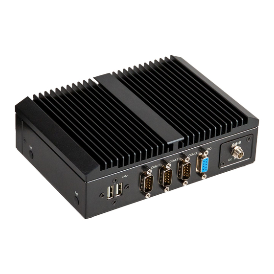
Page 18: Getting Familiar With Your Unit
1 x Headphone HDD LED [Rear Side] [Right Side] 2 x USB 2.0 1 x COM Port (RS-232/422/485 & 2 x Antenna (Optional) RI/5V/12V) 2 x COM Ports (RS-232) 1 x Screw Type DC Jack 1 x GPIO (8 bits) www.gigaipc.com... - Page 19 * Before Connecting the power, make sure to fasten the case securely. [Bottom PCB Side] Information Information 2 x DDR3L SO-DIMM sockets 1 x M.2 slot 2242 M-key 1 x Mini PCIe slot with SIM Slot Support 2.5’’ Hard drive/SSD www.gigaipc.com...
-
Page 20: A) Memory Installation: Ddr3L So-Dimm
A) Memory Installation: DDR3L SO-DIMM www.gigaipc.com... -
Page 21: B) Mini Pcie Card Installation: How To Safely Install
B) Mini PCIe Card Installation: How to safely install the Mini PCIe Card Remove the screw from the screw Carefully insert the Mini PCIe Card hole (Location : MSO1) into the slot. Secure the Mini PCIe Card with screw. www.gigaipc.com... -
Page 22: C) M.2 Ssd Installation: How To Safely Install The
C) M.2 SSD Installation: How to safely install the M.2 2242 SSD Remove the screw from the screw Carefully insert the M.2 SSD into the hole (Location : MSO2) slot, and secure with the screw. www.gigaipc.com... -
Page 23: D) 2.5" Hdd/Ssd Installation: How To Install 2.5
First : assemble the SATA cable and 2.5" HDD/SSD. Second : install 2.5" HDD/SSD (Gold finger of 2.5" HDD/SSD must face down), and secure with 4 screws. Assemble the SATA cable on the SATA connector, and lock the bottom cover. www.gigaipc.com... -
Page 24: Antenna Installation (Antenna Inclusion May Vary Based On Local Distribution)
Antenna Installation (Antenna inclusion may vary based on local distribution) www.gigaipc.com... -
Page 25: Dio (Gpio) Pin Define
This port is limited to only 5V for the Pin No. Pin Define specific end products and are provided GPIO-output_1 with a molded plastic Fire Enclosure. GPIO-input_1 Rated minimum 94V-1 or Metal enclosure. GPIO-output_2 GPIO-input_2 GPIO-output_3 GPIO-input_3 GPIO-output_4 GPIO-input_4 www.gigaipc.com... -
Page 26: Db9 Com Pin Define
DB9 COM Pin Define DB9 COM 25CF8-180620-S9R RS-422 RS-485 Pin No. RS-232 Full Duplex Half Duplex TXD- TXD+ RXD+ — RXD- — — — — — — — — — www.gigaipc.com... -
Page 27: Support
Support ● For a list of tested memory, M.2, 2.5’’ SSD, wireless adapters and OS supported, go to: http://www.gigaipc.com ● To download the latest drivers and BIOS updates, go to: http://www. gigaipc.com ● For product support, go to: http://www.gigaipc.com www.gigaipc.com... -
Page 28: Safety And Regulatory Information
At the end of its serviceable life, this product should not be treated as household or general waste. It should be handed over to the applicable collection point for the recycling of electrical and electronic equipment, or returned to the supplier for disposal. www.gigaipc.com... -
Page 29: Chapter 3 - Hardware Information
Chapter 3 Chapter 3 – Hardware Information www.gigaipc.com GIGAIPC reserves the right to modify or revise the content at anytime without prior notice. -
Page 30: Jumpers And Connectors
Jumpers and Connectors www.gigaipc.com GIGAIPC reserves the right to modify or revise the content at anytime without prior notice. - Page 31 17 SYS_PANEL Front panel header 18 FUSB2_2 USB 2.0 header 19 MPCIE Mini-PCIe slot 20 M2M M.2 slot, 2242 M-key 21 SIM_CARD 3G/4G SIM Slot www.gigaipc.com GIGAIPC reserves the right to modify or revise the content at anytime without prior notice.
- Page 32 24 LAN1, LAN2 2 x RJ45 Ports 2 x USB 3.2 Gen 1 25 FUSB30 26 HDMI HDMI connector 27 VGA VGA Port 28 CLR_CMOS Clear CMOS jumper www.gigaipc.com GIGAIPC reserves the right to modify or revise the content at anytime without prior notice.
-
Page 33: Fan (Fan Connector)
CPU/System FAN Connector PN Vendor 85205-0470N ACES A1250WV-S-04PC JOINT-TECH Connector type 1 2 3 4 1x4pin header, pitch 1.25mm Pin No. Definition Detect Speed Control www.gigaipc.com GIGAIPC reserves the right to modify or revise the content at anytime without prior notice. -
Page 34: Dc In (Dc In 1X4Pin Power Connector)
DC IN (DC IN 1x4pin power connector) Pin1 DC in Connector Connector PN Vendor 753-81-04TW00 PINREX Connector type 1x4pin header, pitch 2.5mm Pin No. Definition DCIN DCIN www.gigaipc.com GIGAIPC reserves the right to modify or revise the content at anytime without prior notice. -
Page 35: Com1, Com2, Com3, Com4 (Serial Port Header)
– COM2, COM3, COM4 : Support RS-232 only RXD+ – – – – – – – – – No Connect – – – – www.gigaipc.com GIGAIPC reserves the right to modify or revise the content at anytime without prior notice. -
Page 36: Spk_Out (Speaker Out Connector)
PINREX A2001WV-04P146 JOINT-TECH Connector type 1x4pin header, pitch 2.0mm Pin No. Definition Speaker Out R+ Speaker Out R- Speaker Out L- Speaker Out L+ www.gigaipc.com GIGAIPC reserves the right to modify or revise the content at anytime without prior notice. -
Page 37: Jcom1 (Ri# Pin Ri#/5V/12V Select Jumper For Com1 Port)
PINREX 1-2 Close: PH06N53BAZ000 HORNGTONG 5V (Power COM) Connector type 3-4 Close: 2x3pin header, pitch 2.0mm RI (Stand COM) 5-6 Close: 12V (Power COM) www.gigaipc.com GIGAIPC reserves the right to modify or revise the content at anytime without prior notice. -
Page 38: Jrs11-Jrs14 (Rs11-14 Select Jumper For Serial Port)
1T/1R RS-422 Pure RS-232 3T/5R RS-232 (Default) RS-485 Half Duplex 1T/1R RS-485, TX ENABLE Low Active RS-485 Half Duplex 1T/1R RS-485, TX ENABLE High Active www.gigaipc.com GIGAIPC reserves the right to modify or revise the content at anytime without prior notice. -
Page 39: At_Cn (At/Atx Mode Select Jumper)
1-2 Close : AT mode. 220-96-03GB01 PINREX 2-3 Close : ATX mode. Connector type (Default setting) 1x3pin header, pitch 2.0mm Pin No. Definition AT MODE Detect ATX MODE www.gigaipc.com GIGAIPC reserves the right to modify or revise the content at anytime without prior notice. -
Page 40: Lsw (Lvds Resolution Jumper)
1280 x 960 1600 x 1200 18bit 24bit 1280 x 1024 1920 x 1080 24bit 24bit 1366 x 768 1920 x 1200 18bit 24bit www.gigaipc.com GIGAIPC reserves the right to modify or revise the content at anytime without prior notice. -
Page 41: Lvds (Lvds Connector)
Note: *The LVDS output connector CLK2+ CLK1+ of the unit is only intended to be CLK2- connected to an UL/IEC/EN approval CLK1- equipment with fire enclosure. www.gigaipc.com GIGAIPC reserves the right to modify or revise the content at anytime without prior notice. -
Page 42: Bkl_Cn (Backlight Control Connector)
3.2.10 BKL_CN (Backlight control connector) Pin1 Backlight control connector Connector PN Vendor 721-81-05TW00 PINREX A2001WV-05P146 JOINT-TECH Connector type 1x5pin header, pitch 2.0mm Pin No. Definition Back Light Enable www.gigaipc.com GIGAIPC reserves the right to modify or revise the content at anytime without prior notice. -
Page 43: Buzzer (Buzzer Header)
3.2.11 BUZZER (buzzer header) Pin1 Buzzer Connector PN Vendor 712-71-02TW01 PINREX A1250WV-02P JOINT-TECH Connector type 1x2pin header, pitch 1.25mm Pin No. Definition SPKR www.gigaipc.com GIGAIPC reserves the right to modify or revise the content at anytime without prior notice. -
Page 44: Battery (Battery Cable Connector)
3.2.12 BATTERY (Battery cable connector) Pin1 Battery Cable Connector Connector PN Vendor 85205-0270L ACES A1250WV-S-02PC JOINT-TECH Connector type Pin No. Definition 1x2pin header, pitch 1.25mm 3.3V RTC www.gigaipc.com GIGAIPC reserves the right to modify or revise the content at anytime without prior notice. -
Page 45: Satapw (Sata Power Connector)
3.2.13 SATAPW (SATA power connector) Pin1 Hard Disk Power Connector Connector PN Vendor 743-81-04TW00 PINREX Connector type 1x4pin header, pitch 2.54mm Pin No. Definition +12V www.gigaipc.com GIGAIPC reserves the right to modify or revise the content at anytime without prior notice. -
Page 46: Sataiii (Sata 6Gb/S Connector)
3.2.14 SATAIII (SATA 6Gb/s Connector) Pin1 SATA 6Gb/S Connector Connector PN Vendor WAT3M-07A1G3BU4W WINWIN ABA-SAT-054-S15 LOTES Pin No. Definition www.gigaipc.com GIGAIPC reserves the right to modify or revise the content at anytime without prior notice. -
Page 47: Fusb2_1, Fusb2_2 (Usb 2.0 Header)
USB 2.0 Header Connector PN Vendor 210-92-05GB04 PINREX PH10R53BAZ009 HORNGTONG Connector type 9 10 2x5pin header, pitch 2.54mm Pin No. Definition No Pin No Connect www.gigaipc.com GIGAIPC reserves the right to modify or revise the content at anytime without prior notice. -
Page 48: Gpio_Cnt (General Purpose Input/Output Header)
PINREX A2004WV-2X06P46 JOINT-TECH Connector type Pin No. Definition 2x6pin header, pitch 2.0mm GPIO-output_1 GPIO-input_1 GPIO-output_2 GPIO-input_2 GPIO-output_3 GPIO-input_3 GPIO-output_4 GPIO-input_4 SMBus Clock SMBus DATA www.gigaipc.com GIGAIPC reserves the right to modify or revise the content at anytime without prior notice. -
Page 49: Sys_Panel (Front Panel Header)
2x5pin header, pitch 2.54mm Pin No. Definition HDD LED+ Power LED+ HDD LED- Power LED- Power Button+ Reset Button Power Button- No Connect No Pin www.gigaipc.com GIGAIPC reserves the right to modify or revise the content at anytime without prior notice. -
Page 50: Mpcie (Mini Pcie Slot)
PCIE Clock n SIM Clock PCIE Clock p SIM Reset Connector PN Vendor UIM VPP3 AS0B221-S99Q-7H FOXCONN WLAN_DISABLE Reset PCIE RXn 3.3V PCIE RXp SMB Clock www.gigaipc.com GIGAIPC reserves the right to modify or revise the content at anytime without prior notice. -
Page 51: M2M (M.2 Slot, 2242 M-Key)
SATA0 TXn 3.3V SATA0 TXp Reset 3.3V 3.3V Pin No. Definition Pin No. Definition 3.3V 3.3V Detect 3.3V 3.3V 3.3V Connector PN Vendor 80159-8521 BELLWETHER www.gigaipc.com GIGAIPC reserves the right to modify or revise the content at anytime without prior notice. -
Page 52: Sim_Card (3G/4G Sim Slot)
3.2.20 SIM_CARD (3G/4G SIM Slot) www.gigaipc.com GIGAIPC reserves the right to modify or revise the content at anytime without prior notice. -
Page 53: Sodimma, Sodimmb (2 X Ddr3L So-Dimm Sockets)
3.2.21 SODIMMA, SODIMMB (2 x DDR3L SO-DIMM sockets) www.gigaipc.com GIGAIPC reserves the right to modify or revise the content at anytime without prior notice. -
Page 54: Lan1, Lan2 (Gbe Lan Connectors)
Orange On 1Gbps data rate Green On 100Mbps data rate 10Mbps data rate Pin No. Definition TX1+ TX1- TX2+ TX2- TX3+ TX3- TX4+ TX4- www.gigaipc.com GIGAIPC reserves the right to modify or revise the content at anytime without prior notice. -
Page 55: Fusb30 (Usb 3.2 Gen 1 Connector)
3.2.23 FUSB30 (USB 3.2 Gen 1 connector) USB Connector Pin No. Definition USB3_RX2n USB3_RX2p USB3_TX2n USB3_TX2p Pin No. Definition USB3_RX1n USB3_RX1p USB3_TX1n USB3_TX1p www.gigaipc.com GIGAIPC reserves the right to modify or revise the content at anytime without prior notice. -
Page 56: Hdmi (Hdmi Connector)
Pin No. Definition Pin No. Definition Detect Detect TX2p TX2p TX2n TX2n TX1p TX1p TX1n TX1n TX0p TX0p TX0n TX0n CLKp CLKp CLKn CLKn www.gigaipc.com GIGAIPC reserves the right to modify or revise the content at anytime without prior notice. -
Page 57: Vga (Vga Port)
3.2.25 VGA (VGA port) D-sub Connector Pin No. Definition Pin No. Definition Green Blue DDCSDA 15 11 HSYNC VSYNC DDCSCL www.gigaipc.com GIGAIPC reserves the right to modify or revise the content at anytime without prior notice. -
Page 58: Clr_Cmos (Clear Cmos Jumper)
Normal Operation (Default setting) Close: Clear CMOS data. Connector PN Vendor 210-91-02GBK2 PINREX Pin No. Definition Connector type Clear CMOS 1x2pin header, pitch 2.54mm www.gigaipc.com GIGAIPC reserves the right to modify or revise the content at anytime without prior notice. -
Page 59: Chapter 4 - Bios
Chapter 4 Chapter 4 – BIOS www.gigaipc.com... -
Page 60: Introduction
Execute command or enter the submenu Increase the numeric value or make + changes Decrease the numeric value or make – changes General Help Previous Values Load Optimized Defaults Settings Save changes & Exit the BIOS Setup program Exit the BIOS Setup program www.gigaipc.com... -
Page 61: The Main Menu
TXE FW version Shows ME firmware version Set the Date for the system System Date (Format : Week - Month - Day - Year) Set the time for the system System Time (Format : Hour - Minute - Second) www.gigaipc.com... -
Page 62: Advanced
Advanced The Advanced menu is to configure the functions of hardware settings through submenu. Use arrow keys to move among the items, and press <Enter> to access into the related submenu. www.gigaipc.com... -
Page 63: Tpm Configuration
4.3.1 TPM Configuration Use TPM Configuration submenu to choose TPM interface. Item Description Enabled : Enables fTPM (Default setting) fTPM Disabled : Disables fTPM www.gigaipc.com... - Page 64 Item Description Security Device Enabled : Enables TPM feature (Default setting) support Disabled : Disables TPM feature None : No execution will be conducted (Default setting) Pending operation TPM clear : Set to clear data on TPM www.gigaipc.com...
-
Page 65: It8786 Super Io Configuration
Enabled : Enables allows you to configure the serial port settings Disabled : if Disabled, displays no configuration for the serial port Serial Port 3 Device settings : Configuration Display the specified Serial Port base I/O address and IRQ www.gigaipc.com... -
Page 66: Hardware Monitor
4.3.3 Hardware Monitor Item Description CPU temperature Shows current CPU temperature System temperature Shows current system temperature www.gigaipc.com... -
Page 67: S5 Rtc Wake Settings
Enable or Disable System to wake on a specific time. Wake system Disabled : Disables system to wake on a specific time (Default setting) from S5 Fixed Time : Enables system to wake on a specific time (Format : hr : min : sec) www.gigaipc.com... -
Page 68: Cpu Configuration
Enabled : Enables Turbo Mode (Default setting) Turbo Mode Disabled : Disables Turbo Mode Command CPU to enter into low power consumption mode when CPU is under idle mode. C-states Enabled : Enables C states (Default setting) Disabled : Disables C states www.gigaipc.com... -
Page 69: Sata Configuration
4.3.6 SATA Configuration Item Description SATA Mode AHCI : Configures the SATA controllers to AHCI mode. (Default setting) Selection SATA shows 2.5" SATA HDD/SSD information shows M.2 SATA interface SSD information www.gigaipc.com... -
Page 70: Csm Configuration
Item Description CSM Support Never : UEFI Mode only (Default setting) When system is power on, install LAN driver under UEFI mode. LAN EFI driver Disabled : Disables UEFI Network Stack (Default setting) Enabled : Enables UEFI Network Stack www.gigaipc.com... -
Page 71: Digital Io Port Configuration
SOGPI_1 (Pin 2) SOGPI_2 (Pin 4) Configure Digital IO Input values for each pin. SOGPI_3 (Pin 6) SOGPI_4 (Pin 8) SOGPO_1 (Pin 1) SOGPO_2 (Pin 3) Configure Digital IO Output values for each pin. SOGPO_3 (Pin 5) SOGPO_4 (Pin 7) www.gigaipc.com... -
Page 72: Chipset
Enable/Disable Watchdog Timer function WatchDog Timer Enabled : Enables Watchdog Timer function Disabled : Disabled Watchdog Timer function (Default setting) Enable/Disable BIOS Lock function BIOS Lock Enabled : Enables BIOS Lock function (Default setting) Disabled : Disabled BIOS Lock funtion www.gigaipc.com... -
Page 73: Security
To set up Administrator's password Administrator Minimum length : 3 Password Maximum length : 20 To set up User's password User Password Minimum length : 3 Maximum length : 20 Secure Boot Press <Enter> to configure the advanced items www.gigaipc.com... - Page 74 Enabled : Enables Secure Boot control function Standard : Standard mode Secure Boot Mode Custom : Custom mode (Default setting) Enables expert users to modify Secure boot policy variables without full Key Management authentication Press <Enter> to configure the advanced items www.gigaipc.com...
- Page 75 Save NVRAM content of all Secure boot varaiables to the files in root folder variables on a target file system device Item Description Platform Key (PK) Key Exchange Keys Authorized Signatures These items allows you to enroll factory defaults or load Certificates from a file. Forbidden Signatures Authorized TimeStamps OsRecovery Signatures www.gigaipc.com...
-
Page 76: Boot
Enabled : Enables Full screen LOGO Show on POST screen LOGO Show Disabled : Disables Full screen LOGO Show on POST screen (Default setting) Boot Option #1 Shows the information of the storage that be installed in the system Boot Option #2 Choose/set the boot priority www.gigaipc.com... -
Page 77: Save & Exit
Yes : Agree to discard changes and reset and Reset No : Cancel to discard changes and reset Restore/Load default values for all the setup options Restore Defaults Yes : Agree to load optimized defaults No : Cancel to load optimized defaults www.gigaipc.com...
Need help?
Do you have a question about the QBiX-Pro-APLC4200H-B2 and is the answer not in the manual?
Questions and answers