
Related Manuals for SKF Linkoln WS-E Series


Summary of Contents for SKF Linkoln WS-E Series
- Page 1 Installation instructions following machinery directive 2006/42/EC Electromotive change-over device/ Electromotive way valve Series EM-U3/ WS-E Version 03...
- Page 2 EC Declaration of incorporation EC Declaration of incorporation following machinery directive 2006/42/EC, annex II, part 1 B The manufacturer, SKF Lubrication Systems Germany GmbH, Walldorf Facilities, Heinrich-Hertz-Str. 2-8, DE - 69190 Walldorf, hereby declares that the partly completed machinery Designation:...
- Page 3 2006/42/EC are part of the described Europe/ Africa/ Middle East/ India tion on the warranty. This can be found in products and must be kept at an accessible SKF Lubrication Systems Germany GmbH our general terms and conditions. location for further use. Copyright Americas/ Asia/ Pacific ©...
-
Page 4: Table Of Contents
Table of contents Table of contents 4. Technical data .....................22 1. Safety instructions ....................8 General safety instructions ..................8 General technical data .................... 22 Electrics ........................23 General behaviour when handling the product ............8 Qualified technical personnel ...................9 Tightening torques and connection dimensions ..........24 Notes related to the type identification plate ............ - Page 5 Table of contents 9. Maintenance, cleaning ..................33 General information ....................33 Maintenance ......................33 Cleaning ........................33 9.4 Check for proper function .................... 33 9.5 Check for damages ....................... 33 10. Troubleshooting ....................34 11. Spare parts .......................35 12. Circuit diagrams....................37 12.1 Circuit diagram EM-U3 24 V DC ................
- Page 6 Explanation of symbols and signs Explanation of symbols and signs Symbols oughly and heed the warning and safety You will find these symbols, which warn of notes. Please observe the warning and specific dangers to persons, material assets, Symbol Meaning safety notes and exercise particular cau- or the environment, next to all safety in- tion in these cases.
- Page 7 Explanation of symbols and signs Abbreviations and conversion factors Abbreviations regarding Ounce approx. approx. pounds per square inch °C degrees Celsius relative humidity cu.in cubic inch second dB (A) sound pressure level sq.in. square inch i.e. that is etc. et cetera etc.
-
Page 8: Safety Instructions
1. Safety instructions 1. Safety instructions 1.2 General behaviour when handling the 1.1 General safety instructions product ○ The product may only be used in aware- Safety information is to be read and ob- or affected otherwise in their function ness of the potential dangers, in proper served by any persons entrusted with works and are to be checked at regular intervals... -
Page 9: Qualified Technical Personnel
Product training can also be performed by down in DIN VDE 0105 and IEC 364. SKF in exchange for costs incurred. Relevant country-specific definitions of qualified technical personnel apply for coun-... -
Page 10: Electric Current Hazard
1. Safety instructions 1.6 Operation 1.4 Electric current hazard 1.5 System pressure hazard The following must be observed during commissioning and operation. WARNING WARNING ○ All information within this manual and System pressure the information within the referenced Electric shock The product is pressurized during documents. -
Page 11: Assembly, Maintenance, Malfunctions, Shutdown, Disposal
The electromotive change-over device EM- ○ Other units of the superior machine of the activity prior to starting any work. U3 has been designed for changing over SKF Precautionary operational measures and must not be damaged or impaired in Duoflex dual-line systems by keeping to the work instructions must be observed. -
Page 12: Foreseeable Misuse
1. Safety instructions 1.9 Foreseeable misuse 1.10 Disclaimer of liability 1.11 Referenced documents Any usage of the product differing from The manufacturer shall not be held respon- In addition to these Instructions, the fol- the aforementioned conditions and stated sible for damages caused by: lowing documents must be observed by the ○... -
Page 13: Residual Risks
1. Safety instructions 1.12 Residual risks Residual risks Remedy Life cycle — transport, assembly, start-up, operation, malfunction, troubleshooting, repair, maintenance, shutdown, disposal ○ No people may remain under suspended loads. Keep unauthorized persons away. Secure suspend- Dropping of lifted parts or tools ed loads using suitable hoisting equipment (e.g. -
Page 14: Lubricants
Regulation EC 1272/2008 annex I, selections. the machine or system in cooperation with part 2-5 may only be filled into SKF central- the lubricant supplier. ized lubrication systems and components When selecting a lubricant, the type of... -
Page 15: Approved Lubricants
ATTENTION using lubricants that meet the specifica- tions in the technical data. Depending on the If required SKF can help customers to se- Only lubricants approved for the product product design, these lubricants may be oils, lect suitable components for feeding the may be used. -
Page 16: Lubricants And The Environment
2. Lubricants 2.4 Lubricants and the environment 2.5 Lubricant hazard ATTENTION WARNING Lubricants may pollute ground and waters. Risk of slipping and injury Lubricants have to be handled and dis- Leaking lubricant is hazardous due posed of properly. Observe the instructions to the risk of slipping and injury. -
Page 17: Overview, Functional Description
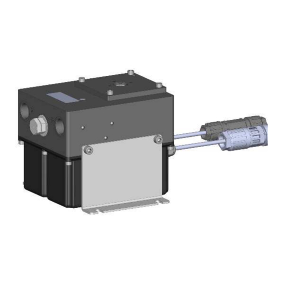
3. Overview, functional description 3. Overview, functional description Overview Fig. 1 Change-over housing Change-over cartridge with oil bleed bore Housing cover Retaining plate, right and left side Electrical input Electrical output Position indicator of change-over cartridge (below protective cap) Motor Power supply board (only 230 V AC) Control printed circuit board Magnetic sensors... -
Page 18: Brief Description Em-U3
Change-over cartridge in position M Fig. 2 The EM-U3 is compact powerful. electro- A M B motive change-over device for SKF DuoFlex dual- line systems. Each of the 3 possible switch positions A, M and B is detected precisely by its own magnetic sensor. -
Page 19: Brief Description Ws-E
3. Overview, functional description 3.2 Brief description WS-E Brief description WS_E Fig. 3 Due to the factory-set closure of certain outlet ports, the WS-E can be used as a reli- able and powerful shut-off and way valve. Fig. 7a Here the middle position M cannot be used. A M B Fig. -
Page 20: General System Description
3. Overview, functional description 3.3 General system description System description Fig. 4 Normally, an SKF Duoflex dual-line system consists of the following components: pump unit (1) with pressure reducing valve, electromotive change-over device (2) EM- U3 resp. way valve WS-E to connect pres- sure line P (3), relief line R (4) and the two main lines A (5) and B (6). -
Page 21: Em-U3 As A Replacement Of Em-U2
3. Overview, functional description 3.4 EM-U3 as a replacement of EM-U2 For assembly of the EM-U3 as a replace- If EM-U3 shall be used as a replacement of ment of an EM-U2 proceed as follows: EM-U2, observe the following points: •... -
Page 22: Technical Data
4. Technical data 4. Technical data 4.1 General technical data Admissible operating temperature -20 °C to +70 °C Operating pressure 400 bar max. Flow rate 400 l/h max. Line connections 4 x G3/4 Installation position Change-over time 5 sec max. Minimum distance between 2 switching pulses 2 sec min. -
Page 23: Electrics
4. Technical data 4.2 Electrics 24 V DC 230 V AC Operating voltage 24 V DC ± 10 % 230 V AC ± 10 % Current consumption 2.1 A max. 0.23 A max. Power consumption 50 W max. 50 W max. External fuse protection 6 A (T) None, protected internally with 2 A (T) -
Page 24: Tightening Torques And Connection Dimensions
4. Technical data 4.3 Tightening torques and connection dimensions Tightening torques and connecting dimensions Fig. 5 Adhere to the following tightening torques when installing or repairing the pump. Supply lines (A, B, P, R) 120 Nm ± 5 Nm Lower part of housing with housing (5) 3 Nm ±... -
Page 25: Notes Related To The Type Identification Plate
4. Technical data 4.4 Notes related to the type identiication 4.5 Notes related to the CE marking plate CE marking is effected following the requirements of the applied directives: The type identification plate states impor- ○ 2014/30/EU Electromagnetic compatibility tant characteristics such as type designa- ○ 2011/65/EU (RoHS II) Directive on the restriction of the use of certain hazardous sub- tion, order number, etc. -
Page 26: Delivery, Returns, And Storage
5.1 Delivery 5.3 Storage Clean all parts and pack them properly The products are packaged following the SKF products are subject to the following before returning them. Protect the product standard commercial practice according to storage conditions: ○ dry and dust-free surroundings, storage against mechanical influences such as im- the regulations of the recipient's country. -
Page 27: Assembly
6. Assembly 6. Assembly 6.1 General information 6.2 Attachment Only qualified technical personnel may Protect the product against humidity and install, operate, maintain, and repair the vibration and install it in an easily accessible CAUTION products described in these Instructions. position to ensure all other installations can Qualified technical personnel are persons be carried out without any problem. -
Page 28: Minimum Assembly Dimensions
6. Assembly 6.3 Minimum assembly dimensions Minimum assembly dimensions Fig. 8 Ensure sufficient space for maintenance work or for a possible disassembly of the product by leaving a free space of at least 50 mm into each direction in addition to the stated dimensions. -
Page 29: Electrical Connection
6. Assembly 6.4 Electrical connection 6.5 Assignment of the power supply 6.6 Assignment of the power supply Assignment of the power supply Fig. 9 Assignment of the control line Fig. 10 WARNING M-IN Power supply (230 V AC) Electric shock B-IN (Ground optional 24 V DC) The electrical connection may be... -
Page 30: How To Lay The Lubrication Lines
6. Assembly 6.7 How to lay the lubrication lines cording to the maximum operating pressure bricant flow direction. Design cross section When laying the lubrication lines, observe of the annular gear unit, the admissible tem- transitions as smooth as possible. the following information in order to warrant peratures and the lubricants to be supplied. -
Page 31: Start-Up
7. Start-up 7. Start-up After correct electrical connection of the control and power supply lines as well as the correct connection of the tube lines com- missioning of the EM-U3/ WS-E shall be carried out by qualified personnel following the start-up prescriptions of the overall system. -
Page 32: Operation, Shutdown And Disposal
8. Operation, shutdown and disposal 8. Operation, shutdown and disposal 8.1 Operation 8.3 Shutdown and disposal In case of final shutdown follow the appli- The EM-U3/ WS-E operates automatically. cable rules and regulations on disposal. The product can also be returned to the manu- 8.2 Temporary shutdown facturer for proper disposal, in which case A temporary shutdown of the described... -
Page 33: Maintenance, Cleaning
9. Maintenance, cleaning 9. Maintenance, cleaning 9.1 General information 9.4 Check for proper function Position indication Fig. 12 Liability is excluded for any damage or faults • Remove protective screw. arising from inappropriate maintenance, • Trigger control pulse on the PLC con- repair or cleaning. -
Page 34: Troubleshooting
10. Troubleshooting 10. Troubleshooting Mechanical faults on pumps with and without controller Fault Possible causes of the fault/ visible Remedy Wear on the piston of the change-over cartridge Grease leaking from the leak grease bore of the change-over cartridge. Replace change-over No pressurization/ too slow pressurization cartridge. -
Page 35: Spare Parts
11. Spare parts 11. Spare parts The spare parts assemblies may be used exclusively for replacement of identical defective parts. Modifications with spare parts on existing products are not allowed. Spare parts Fig. 13 1: Change-over cartridge assy. Part no.: 518-34960-1 2a: Control pcb (24 V DC) Part no.: 518-34960-2 2b: Control pcb (230 V AC) - Page 36 11. Spare parts Order number: Product description Hydraulic connections EMU-03-00-0000+924 EM-U3 24 V DC version No closed connections EMU-03-00-0000+1KF EM-U3 230 V AC version No closed connections EMU-22-66-0000+924 WS-E 2/2 way valve 24 V DC version Connections B and R closed EMU-22-66-0000+1KF WS-E 2/2 way valve 230 V AC version...
-
Page 37: Circuit Diagrams
12. Circuit diagrams 12. Circuit diagrams 12.1 Circuit diagram EM-U3 24 V DC Circuit diagram 24 V DC Abb. 14... -
Page 38: Flow Diagram Em-U3 24 V Dc
12. Circuit diagrams 12.2 Flow diagram EM-U3 24 V DC Signals EM-U3 24 V DC Fig. 15... -
Page 39: Circuit Diagram Em-U3 230 V Ac
12. Circuit diagrams 12.3 Circuit diagram EM-U3 230 V AC Circuit diagram 230 V AC Fig. 16... -
Page 40: Flow Diagram Em-U3 230 V Ac
12. Circuit diagrams 12.4 Flow diagram EM-U3 230 V AC Signals EM-U3 230 V AC Fig. 17... - Page 41 Notes...
- Page 42 A global presence provides SKF customers uniform quality standards and worldwide product availability. Important information on product usage All products from SKF may be used only for their intended purpose as described in this brochure and in any instructions. If operating instructions are supplied with the products, they 951-171-001-EN must be read and followed.
Need help?
Do you have a question about the Linkoln WS-E Series and is the answer not in the manual?
Questions and answers