National Instruments PXIe-5665 Getting Started Manual
3.6 ghz or 14 ghz vector signal analyzer
Hide thumbs
Also See for PXIe-5665:
- Calibration manual (85 pages) ,
- Getting started manual (10 pages) ,
- Getting started manual (9 pages)
Table of Contents
Advertisement
Quick Links
Advertisement
Table of Contents

Related Manuals for National Instruments PXIe-5665


Summary of Contents for National Instruments PXIe-5665
- Page 1 PXIe-5665...
-
Page 2: Table Of Contents
This document explains how to install, configure, and test the PXIe-5665. The PXIe-5665 is a 3.6 GHz or 14 GHz modular RF vector signal analyzer (VSA). The PXIe-5665 ships with the NI-RFSA instrument driver, which you can use to program the device. You can also use NI-RFmx, available at ni.com/downloads, to program the device. -
Page 3: Electromagnetic Compatibility Guidelines
3 meters in length. Verifying the System Requirements To use the PXIe-5665, your system must meet certain requirements. For more information about minimum system requirements, recommended system, and supported application development environments (ADEs), refer to the readme, which is available on the software media or online at ni.com/updates. - Page 4 Do not install a device if it appears damaged in any way. Note Unpack any other items and documentation from the kit. Store the device in the antistatic package when the device is not in use. PXIe-5665 Getting Started Guide | © National Instruments | 3...
-
Page 5: Verifying The Kit Contents
13. PXIe-5665 Getting Started Guide (This 6. 3.6 GHz Version: Flexible 5-inch RF SMA-to-SMA Document) Cable, Part Number 190412B-05. 14 GHz Version: Flexible 7-inch RF SMA-to-SMA Cable, Part Number 190412B-07. 7. SMA Driver Bit, Part Number 190487A-01 4 | ni.com | PXIe-5665 Getting Started Guide... -
Page 6: Preparing The Environment
PXIe-5653 front panel to the REF IN connector on the back of the PXI Express chassis. NI-RFSA versions 2.5 and later do not require this connection. Preparing the Environment Ensure that the environment you are using the PXIe-5665 in meets the following specifications. Operating ambient temperature 0 °C to 55 °C... -
Page 7: Choosing And Installing The Software
Choosing and Installing the Software Software Options NI provides several software options for the PXIe-5665—NI-RFmx, the NI-RFSA instrument driver software, and the NI-RFSA Soft Front Panel (SFP). Table 1. PXIe-5665 Software Options Software Description Use Case Option NI-RFmx Provides a single-handle... -
Page 8: Installing The Pxie-5665
5. PXI Express Peripheral Slot 3. PXI Express Hybrid Peripheral Slot PXIe-5665 modules can be placed in PXI Express peripheral slots, PXI Express hybrid peripheral slots, or PXI Express system timing slots. Touch any metal part of the chassis to discharge static electricity. -
Page 9: Interconnecting The Pxie-5665 Modules
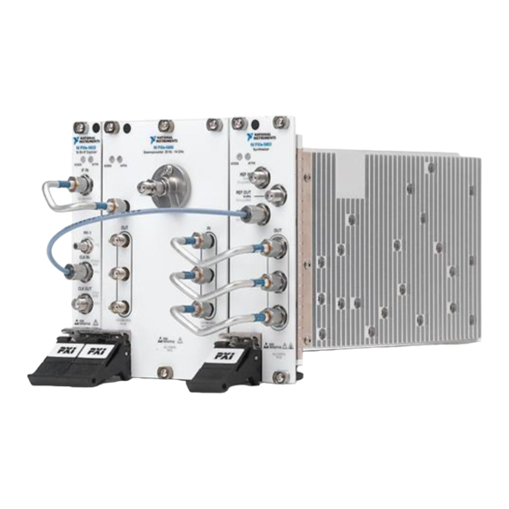
Installing the Software on page 6 Interconnecting the PXIe-5665 Modules Complete the following steps to interconnect the PXIe-5665 front panel connectors using the PXIe-5603 downconverter, as shown in Figure 3, or the PXIe-5605 downconverter, as shown in Figure 4. The signal pins of this product's input/output ports can be damaged if Caution subjected to ESD. - Page 10 50 Ω ALL PORTS 50 Ω 1. Short, Silver Flexible RF SMA-to-SMA Cable 3. Short, Semi-Rigid SMA-to-SMA Cable, Labeled K 4. 50 Ω Termination Load 2. Flexible RF SMA-to-SMA Cable PXIe-5665 Getting Started Guide | © National Instruments | 9...
- Page 11 Figure 5. PXIe-5665 14 GHz Front Panel Interconnection NI PXIe-5622 NI PXIe-5605 NI PXIe-5653 Downconverter 20 Hz - 14 GHz Synthesizer 16-Bit IF Digitizer ACCESS ACTIVE ACCESS ACTIVE IF IN REF IN RF IN 10 MHz 0 V DC 5 V p-p MAX +20 dBm MAX >...
- Page 12 Refer to the NI RF Vector Signal Analyzers Help for information about how to connect the PXIe-5665 using an external clock or how to connect multiple PXIe-5665 modules. Direct Connections to the PXIe-5603 or PXIe-5605 The PXIe-5603 or PXIe-5605 is a precision RF instrument that is sensitive to ESD and transients.
- Page 13 The signal pins of this product's input/output ports can be damaged if subjected to ESD. To prevent damage, turn off power to the product before connecting cables and employ industry-standard ESD prevention measures during installation, maintenance, and operation. 12 | ni.com | PXIe-5665 Getting Started Guide...
- Page 14 Table 3. PXIe-5603 or PXIe-5605 RF Downconverter Module Front Panel Connectors Connector RF IN Connects to the analog RF input signal to be measured by the PXIe-5665. The PXIe-5603 or PXIe-5605 downconverter module has no Note internal DC block. High-frequency components in the PXIe-5603 or PXIe-5605 can be damaged when DC signals are applied directly to the RF IN connector.
- Page 15 LO signals when daisy-chaining the signals to other RF downconverter modules. When you are not using the LO OUT connectors, connect a 50 Ω termination load to each of these connectors. 14 | ni.com | PXIe-5665 Getting Started Guide...
- Page 16 If the power supply fails, contact NI technical support. PXIe-5665 Getting Started Guide | © National Instruments | 15...
- Page 17 Figure 7. PXIe-5622 IF Digitizer Module Front Panel 16-Bit IF Digitizer ACCESS ACTIVE IF IN + 20 dBm MAX 50 Ω PFI 1 CLK IN 6.3 Vp-p 50 Ω CLK OUT 2 Vp-p 50 Ω SENSITIVE 16 | ni.com | PXIe-5665 Getting Started Guide...
- Page 18 50 Ω (nominal). The output power delivered to a 50 Ω load is >10 dBm. PFI 1 Receives a digital trigger from an external source. PFI 1 is an SMB connector and has an absolute voltage rating of ‑3.3 V to +8 V. PXIe-5665 Getting Started Guide | © National Instruments | 17...
- Page 19 RED—The module has detected an error state. An error state may indicate the module has exceeded approved operating temperature and thermal shutdown has occurred or that the module has detected a power supply failure. If the power supply fails, contact NI technical support. 18 | ni.com | PXIe-5665 Getting Started Guide...
- Page 20 REF OUT 10 MHz 1.5 V p-p MAX REF OUT 100 MHz 1.5 V p-p MAX 800 MHz 4 GHz 3.2 GHz - 8.3 GHz SENSITIVE ALL PORTS 50 Ω PXIe-5665 Getting Started Guide | © National Instruments | 19...
- Page 21 Connects to the LO1 IN connector on the PXIe-5603 or PXIe-5605 module front panel. This connector is the output terminal for the LO1 (3.2 GHz to 8.3 GHz) source. LO1 OUT is an SMA connector with an impedance of 50 Ω (nominal). 20 | ni.com | PXIe-5665 Getting Started Guide...
- Page 22 If the power supply fails, contact NI technical support. The PXIe-5653 LO source has 10 MHz and 100 MHz reference outputs. For Note best performance, connect the 100 MHz REF OUT connector to the PXIe-5622 CLK IN connector. PXIe-5665 Getting Started Guide | © National Instruments | 21...
-
Page 23: Configuring The Pxie-5665 In Max
In the Associated Devices section, select the appropriate module from each system component drop-down listbox. For the PXIe-5665, you must associate the PXIe-5622 IF digitizer module and the PXIe-5653 LO source module with the PXIe-5603 or PXIe-5605 RF downconverter. Click Save in the MAX toolbar. -
Page 24: Self-Calibration
You can determine and reduce these undesired effects through self- calibration, which adjusts the PXIe-5665 with respect to an onboard high-precision calibration tone. Additionally, you should periodically run a self-calibration to adjust for performance drifts that occur with product aging. -
Page 25: Locating The Software And Examples
Windows 10 (32-bit)/8.1 (32-bit)/7 (32-bit)— Program Files\National Instruments • Windows 10 (64-bit)/8.1 (64-bit)/7 (64-bit)— Program Files (x86)\National Instruments Microsoft .NET For the location of .NET class libraries, refer to the installed NI-RFmx readme. 24 | ni.com | PXIe-5665 Getting Started Guide... - Page 26 Program Files (x86)\IVI Foundation\IVI Microsoft .NET To use the .NET API, you must install the .NET class libraries. For download and installed file locations, visit ni.com/info and enter Info Code NETAPIdriversupport PXIe-5665 Getting Started Guide | © National Instruments | 25...
-
Page 27: Programming Examples Locations
NI Example Finder to locate programming examples. Launch LabVIEW or LabWindows/CVI. Select Help»Find Examples to open the NI Example Finder. Navigate to Hardware Input and Output»Modular Instruments. Open the example that best matches your application requirements. 26 | ni.com | PXIe-5665 Getting Started Guide... -
Page 28: Troubleshooting
Users\Public\Public Documents <NIDocDir> directory. \National Instruments LabVIEW examples that demonstrate integration of the PXIe-5665 with NI Note RF vector signal generators and NI toolkit software, including the NI Modulation Toolkit, are also available online at ni.com/examples. Troubleshooting If an issue persists after you complete a troubleshooting procedure, contact NI technical support or visit ni.com/support. -
Page 29: Configuration
What Should I Do if the Device Does Not Initialize? Failure to initialize may indicate a problem with module interconnections or with MAX. If the niRFSA Initialize VI or the niRFSA_init function returns an error and the PXIe-5665 fails to initialize, complete the following steps: Reconnect the PXIe-5665 hardware module front panel cables securely. -
Page 30: Measurements
What Should I Do if the Device Amplitude Reading Does Not Match the Source? Verify that the discrepancy between the PXIe-5665 and the source is within the error limits of the devices. Verify the absolute amplitude accuracy of the PXIe-5665 using the appropriate value. -
Page 31: Where To Go Next
The NI website is your complete resource for technical support. At ni.com/support, you have access to everything from troubleshooting and application development self-help resources to email and phone assistance from NI Application Engineers. 30 | ni.com | PXIe-5665 Getting Started Guide... - Page 32 United States, visit the Worldwide Offices section of ni.com/ niglobal to access the branch office websites, which provide up-to-date contact information, support phone numbers, email addresses, and current events. PXIe-5665 Getting Started Guide | © National Instruments | 31...
- Page 33 For patents covering NI products/technology, refer to the appropriate location: Help»Patents in your patents.txt ni.com/patents software, the file on your media, or the National Instruments Patent Notice at . You can find information about end-user license agreements (EULAs) and third-party legal notices in the readme file for your NI product. Refer ni.com/legal/export-compliance...
Need help?
Do you have a question about the PXIe-5665 and is the answer not in the manual?
Questions and answers