
Related Manuals for Marshall Electronics Orchid OR-702


Summary of Contents for Marshall Electronics Orchid OR-702
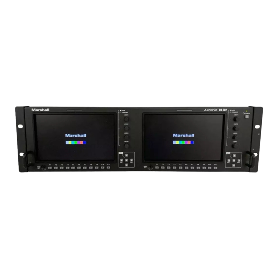
- Page 1 Marshall Electronics OR-702 High-End 3RU Dual 7” Rack Mount Monitor Operating Instructions...
-
Page 2: Table Of Contents
Contents Product Overview ..................................... 3 Features ......................................3 Installation and Initial Setup ................................. 5 Unpacking ......................................5 Mounting ......................................5 Connections and Power-On ................................5 Front Panel Features ..................................6 Power Button ..................................... 6 Input Select Buttons ..................................6 User-Definable Function Buttons ..............................6 Image Adjustment Knobs ................................. -
Page 3: Product Overview
Product Overview The Orchid OR-702 is a Dual 7” 3RU fully featured rack mount monitor system. The OR-702 offers built-in Waveform Monitor, Vectorscope, Audio Bars, audio output, and several diagnostic tools. This monitor is ideal for use in control rooms, media duplication facilities, and remote vans. The OR-702 provides a complete Audio /Video monitoring solution for 4 HD/SD-SDI feeds when combined with a Marshall audio monitor (AR-AM series). - Page 4 Precision Audio Level Meters De-embeds and displays up to 16 channels of audio using sixteen 64-segment tri-color Audio Meters with user-adjustable reference levels. The Audio Level Meters provide numerical indicators and headroom levels, as well as peak hold function. Audio Channel Loss Warning prevents errors during monitoring.
-
Page 5: Installation And Initial Setup
Inspect the unit for any physical damage that may have occurred during shipping. Should there be any damage, immediately call Marshall Electronics Customer Service at (800) 800-6608. If you are not located within the continental United States, call +1 (310) 333-0606. -
Page 6: Front Panel Features
Front Panel Features Power Button with Indicator Press power switch to turn on the power. The unit and indicator lights will turn on. Press again to turn off the power. Tri-Color Tally Light 30mm Tri-Color tally lamp controlled via the Remote connector on the rear of the unit. -
Page 7: Rear Panel Features
Rear Panel Features Parallel Remote RJ-45 Pin Assignments Pin 1 GPI 1 Pin 2 GPI 2 Pin 3 GPI 3 Pin 4 GPI 4 Pin 5 Pin 6 GPI 5 Pin 7 GPI 6 Pin 8 GPI 7 GPI Input RJ-45 connector for 7 user-assignable GPI inputs. -
Page 8: Compatible Input Formats
OR-702 Compatible Formats Format HD/SD-SDI Optional DVI Optional Component Module Module 480 / 60i ü ü 576 / 50i ü ü 480 / 60p ü 576 / 50p ü 720 / 60p ü 720 / 50p ü 720 / 30p ü... -
Page 9: On-Screen Menu
On-Screen Menu OR-702 MENU STRUCTURE OVERVIEW MODEL NAME OR-702 OPTION CARD OPTION S/N INPUT INFO [1080i / 60] INPUT FORMAT 1080i / 60 COLOR MATRIX COLOR TEMP VERSION 0.0.0.0 RETURN INPUT [SDI] INPUT SELECT SDI 1 / SDI 2 / Option Analog Calibrate >... - Page 10 On-Screen Menu (continued) OR-702 MENU STRUCTURE OVERVIEW RETURN LEVEL METER ON / OFF METER BACKGROUND ON / OFF DISPLAY CHANNELS 1~16 ACTIVE CH ONLY ACTIVE, ALL METER COLUMNS DUAL, QUAD DISP TYPE OVERLAP, OVERLAY FRONT VOLUME 0 to 40 AUDIO [ON] REAR VOLUME 0 to 40 HEADROOM START...
- Page 11 On-Screen Menu (continued) COLOR CHANNEL SCAN ASPECT ZOOM HV DELAY MARKER AUDIO METER AUDIO PRESET 1 AUDIO PRESET 2 AUDIO PRESET 3 USER ASSIGN F-1 THRU F-11 AUDIO PRESET 4 AUDIO PRESET 5 AUDIO PRESET 6 AUDIO PRESET 7 AUDIO PRESET 8 LAYOUT A LAYOUT B WAVEFORM MON...
-
Page 12: Main Menu And Navigation
On-Screen Menu (continued) R TALLY G TALLY B TALLY LEFT R TALLY PIN 1 THRU 8 REMOTE (Pin 5 is Ground) LEFT G TALLY LEFT B TALLY RIGHT R TALLY RIGHT G TALLY RIGHT B TALLY RETURN FORMAT DISP AUTO / ON / OFF TIMECODE OFF / LITC / VITC1 / VITC2 ALWAYS ON... -
Page 13: Color Submenu
Brightness • Varies between 0 and 100, 50 is standard. • 50 is default value with standard black level. • Increasing brightness level allows user to see BTB (Blacker-than-Black). Contrast • Varies between 0 and 100 (80 is standard). • 80 is default value with 100% gain of video signal. Saturation •... -
Page 14: Screen Submenu
SCREEN SUBMENU ■ Scan Normal (Zero Scan) • Whole picture should be visible without any cropping. • When in normal mode, it should not see non-active areas such as SAV, EAV. Over (End-User TV Production Scan) • 5% of the picture is cropped and zoomed to fill the screen. •... -
Page 15: Shift V
■ Shift V Use the Up-éand Down-ê menu buttons to change the value of this setting, which will shift the picture Vertically. Negative values will move the picture DOWN, while Positive values will move the picture UP. MARKER CONFIGURATION SUBMENU ■... -
Page 16: Audio Configuration Submenu
AUDIO CONFIGURATION SUBMENU ■ Level Meter Selects whether or not to display audio level meters. ■ Meter Background Selects whether or not to display meter background. ■ Display Channels Selects how many audio meters you want to display. You may select any number of channels from 1 to 16. ■... -
Page 17: Save Ch Preset
■ Save CH Preset To > Use this menu to select which one of 8 memory locations where the user wants to store the current channel output assignments. ■ CH Preset Use this menu to Lock or Unlock the ability to save to the Ch Preset memory locations. This helps to prevent accidental overwriting of stored presets. -
Page 18: Vectorscope Submenu
VECTORSCOPE SUBMENU ■ Layout Use this menu to choose from several available preset screen layouts. Choosing any of the available preset layouts will override the settings in the Vectorscope, Size, and Position menus. ■ Vectorscope Use this menu to turn the Vectorscope display On or Off when in the Normal mode. ■... -
Page 19: User Assign Submenu
Y Limits (These values are shared with WFM settings) Set luminance upper and lower limits to be monitored. • Limits are displayed in IRE unit • Varies between -7.3 IRE and 109.1 IRE • This value will be shown in WFM window as red line •... -
Page 20: Remote Submenu
REMOTE SUBMENU ■ Pin 1 through Pin 8 The RJ-45 Remote connector on the rear panel has 8 pins. Pin 5 is Ground, while the remaining 7 pins are pulled high to 3.3VDC and may be used for Tally or other Remote Commands. - Page 21 ■ TimeCode Selects among to following options: OFF / LTC / VITC1 / VITC2. In the most cases, the value of LTC and VITC1 will be identical to each other. ■ Power Save • When enabled, the monitor will go to sleep after a predefined time has passed when loss of picture occurs. •...
-
Page 22: Specifications
Specifications ■ PANEL Screen Size 7” Diagonal Display Area (h x v) 6” x 3.6” Aspect Ratio 16:10 (16:9 / 4:3 Selectable) Pixels 800 x 480 Color Depth 8-bit (16.7M Colors) Viewing Angle (h x v) -55°~+65° x -40° ~+50° (CR >10) 350 cd/m 2 Brightness Contrast Ratio... -
Page 23: Maintenance / Color Calibration Procedure
Maintenance / Color Calibration Procedure ■ Screen Cleaning Periodically clean the screen surface using ammonia-free cleaning wipes (Marshall Part No. V-HWP-K). A clean micro-fiber cloth can also be used using only non-abrasive and ammonia-free cleaning agents. Do not use paper towels. Paper towel fibers are coarse and may scratch the surface of the polycarbonate faceplate or leave streaks on the surface. -
Page 24: Warranty Information
This warranty is extended to the first consumer only, and proof of purchase is necessary to honor the warranty. If there is no proof of purchase provided with a warranty claim, Marshall Electronics reserves the right not to honor the warranty set forth above. Therefore, labor and parts may be charged to the consumer.
Need help?
Do you have a question about the Orchid OR-702 and is the answer not in the manual?
Questions and answers