Table of Contents
Advertisement
Quick Links
Advertisement
Table of Contents

Related Manuals for Marshall Electronics OR-185-3GSDI


Summary of Contents for Marshall Electronics OR-185-3GSDI
-
Page 1: User Manual
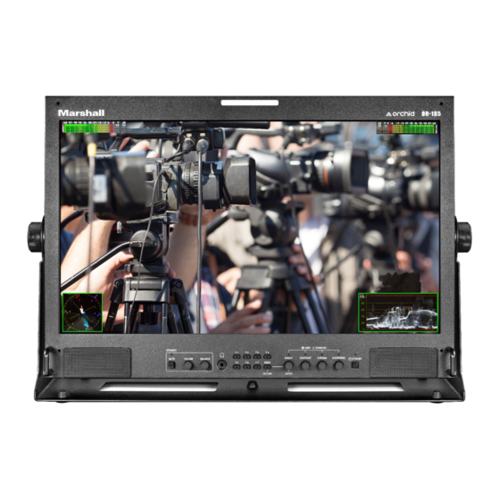
OR-185-3GSDI 18.5” Master Confidence Monitor User Manual... -
Page 2: Table Of Contents
OR-185-3GSDI Table of Contents Introduction ............................... 4 Product Overview ............................. 4 Features ..............................6 Specifications ............................7 Installation and Connections ........................9 Installation and Connect ........................ 9 Video Input Connectors ......................... 9 Audio Input & Output ........................9 Power Input ..........................10 Optional Inputs (GPI, RJ-45 Remote / Service Port) .............. - Page 3 OR-185-3GSDI IMPORTANT SAFETY INSTRUCTIONS: The OR-185-3GSDI HD High Resolution Monitor has been tested for conformance to safety regulations and requirements, and has been certified for international use. However, like all electronic equipment, this unit should be used with care. Please read and follow the safety instructions to protect yourself from possible injury and to minimize the risk of damage to the unit.
-
Page 4: Introduction
Peak Alarm, along with 3D monitoring and analysis functions. The OR-185-3GSDI uses a 1920 x 1080 Full HD panel that can display high-quality images from any source or aspect ratio. All OR-185-3GSDI screens are color matched at the factory and can be auto-adjusted in the field using an optional color probe system (Konica Minolta CA-310 Color Analyzer). - Page 5 OR-185-3GSDI Rear Panel 1. Main Power Switch This switch is the Main power switch. When using the AC power or an external DC supply, this switch will control the On/Off status of the monitor. When using AC power, both switches must be on.
-
Page 6: Features
High Resolution 18.5” Panel The OR-185-3GSDI features an all-digital TFT-MegaPixel active matrix LCD system. The LCD panel features a brightness of 300 cd/m2 and a contrast ratio of 1000:1 making each display ideal in a variety of environments and lighting conditions. -
Page 7: Specifications
OR-185-3GSDI 4. Specifications Type TFT-LCD Display Area 408.96 x 230.4, 18.5" (Diagonally) Pixels 1920(H) x 1080(V), Full HD Pixel Pitch 0.213 (H) x 0.213 (V) (mm) Panel Color Depth 16.7M (8bit), true color Brightness 300 (cd/m²) (cd/m²) Contrast 1000:1 Ratio... - Page 8 OR-185-3GSDI SMPTE 296M YCBCR, 4:2:2, 10-bit 720p (60/59.94/50/30/29.97/25/24/23.98) SMPTE 125M 525i (NTSC, 480i60) ITU-R BT.601 625i (PAL, 575i50) CVBS NTSC, PAL, 480i60, 575i50 480i/480p/575i/576p/720p/1080i/1080p ANALOG COMPONENT 640x480/800x600/1024x768/1280x1024 @60Hz CE Video format IT Video format (VGA HDMI Sync CEA-861-E (IBM VGA), SGA,...
-
Page 9: Installation And Connections
• AC Power cord Mounting The OR-185-3GSDI is designed to be a tabletop production monitor. Attached stand and tilt handle are included. Optional rack mount kit can be purchased. Connections and Power The OR-185-3GSDI uses a standard AC power outlet (100~220VAC) or a 24VDC 4-pin XLR power supply. Connect the required cables for video signal input and output (must be powered for the active loop-outputs to be activated). -
Page 10: Power Input
After connecting the AC power, Switch under the button to the ON Position 5.5 Optional Inputs (GPI, RJ-45 Remote / Service Port) RJ-45 connector for GPI Inputs Service Port for firmware upgrades and LCD color balance calibration, please contact Marshall Electronics before using this port. User Manual v1.0... -
Page 11: Dimensions
OR-185-3GSDI 6. Dimensions User Manual v1.0... -
Page 12: Navigation Menu
OR-185-3GSDI 7. Navigation Menu Main Menu: Push the MENU control button on the monitor to adjust the function configurations. To change configurations, select a configuration from the main menu by turning the knob and pressing the menu button once to select. Edit configuration by turning knob to change levels, then press menu button again to confirm the changes. -
Page 13: Picture Configuration Submenu
OR-185-3GSDI 7.2 Picture Configuration Submenu ITEMS OPTIONS Picture Configuration Return Brightness Levels 0-100 Contrast Levels 0-100 Chroma Levels 0-100 Sharpness Levels 0-100 Gamma Levels 1.00 - 3.00 (increments of .05) Reset to Default Cancel, Reset Now 7.3 Color Configuration Submenu... -
Page 14: Screen Configuration Submenu
OR-185-3GSDI 7.4 Screen Configuration Submenu ITEMS OPTIONS Screen Configuration Return Scan Normal, Overscan, Magnify, PXBYPX Aspect Auto, 4:3, 16:9, 1.85:1, 2.35:1, Payload Mono/Color RGB, Mono, Red, Green, Blue HV Delay Off, On Shift H Levels -128 to +127 Shift V... -
Page 15: Audio Configuration Submenu
OR-185-3GSDI 7.6 Audio Configuration Submenu ITEMS OPTIONS Audio Configuration Return Front Volume Levels 0-40 Headroom Start Levels -0dB to -60dB Headroom End Levels -0dB to -60dB Left Channel Channel Level 1-16 Right Channel Channel Level 1-16 Load Channel Preset From... -
Page 16: Waveform Configuration Submenu
OR-185-3GSDI Display Type Overlap, Overlay Audio Peak Log Off, On Log Speed 4S, 8S, 20S, 60S, 120S, 300S Size Small, Large Position Left Top, Left Bottom, Right Top, Right Bottom Audio Phase Mon Off, On x1, On x2, On x4, On x8... -
Page 17: Vectorscope Configuration Submenu
OR-185-3GSDI 7.9 Vectorscope Configuration Submenu ITEMS OPTIONS Vectorscope Configuration Return Layout Normal, Deck, Quad Vectorscope Off, On Size Small, Medium, Large Position Left Top, Left Bottom, Right Top, Right Bottom Display Type Overlap, Overlay Gain Levels x1.00 to x4.98 7.10 ClipGuide Configuration Submenu... -
Page 18: User Assign Configuration Submenu
OR-185-3GSDI 7.11 User Assign Configuration Submenu F1, F2, F3, F4, F5, F6, F7 Custom Buttons Use this setting to customize the F1-F7 buttons on the monitor’s keypad. Choose between the following options: • • SDI 1 Layout WFM • •... -
Page 19: Remote Configuration Submenu
OR-185-3GSDI 7.12 Remote Configuration Submenu PIN 1, PIN 2, PIN 3, PIN 4, PIN 5, PIN 6, PIN 7, PIN 8 remote control Use this setting to customize the how pins 1 to 8 function. Choose between the following options: •... -
Page 20: Sdi Configuration Submenu
OR-185-3GSDI 7.13 SDI Configuration Submenu ITEMS OPTIONS SDI Status Configuration Return Error Count Reset Counter Display Off, On, Auto 7.14 IMD Configuration Submenu ITEMS OPTIONS IMD Configuration Return Off, On Color White, Red, Blue, Green Preset IMD Camera 1, Camera 2, Monitor 1, Monitor 2, VTR 1, VTR 2,... -
Page 21: Setup Configuration Submenu
OR-185-3GSDI 7.15 Setup Configuration Submenu ITEMS OPTIONS Setup Configuration Return Format Display Auto, On, Off VPID Detect Off, On Timecode Off, LTC, VITC1, VITC2 Size Small, Large Position Top, Bottom UserBit Off, On Power Save Always On, 2 Min, 5 Min, 10 Min, 30 Min, 1 Hour, 2 Hour... -
Page 22: Color Calibration
OR-185-3GSDI 8. Color Calibration Color Calibration: • Allow both the unit to be calibrated and the Minolta® CA-310 to warm up for a minimum of 20 minutes. • Attach the CA-310 color probe to the update dongle. • With the unit turned on, insert the update dongle into the service port at the rear of the device. -
Page 23: Monitor Care
This warranty is extended to the first consumer only, and proof of purchase is necessary to honor the warranty. If there is no proof of purchase provided with a warranty claim, Marshall Electronics, Inc. reserves the right not to honor the warranty set forth above.
Need help?
Do you have a question about the OR-185-3GSDI and is the answer not in the manual?
Questions and answers