
Subscribe to Our Youtube Channel
Related Manuals for Vortice Vort PIV W Series


Summary of Contents for Vortice Vort PIV W Series
- Page 1 Instructions booklet Libretto istruzioni Vort PIV W Vort PIV W RH Vort PIV W RH RF Vort PIV W LH Vort PIV W LH RF COD. 5.671.084.137 16/03/2023...
-
Page 2: Table Of Contents
Safety/Warnings ......5 Vortice cannot assume any responsibility for Configurations ......6 damage to property or personal injury resulting from General warnings for the Installer . -
Page 3: General Information
Before installing and using the appliance, read the warnings in this manual carefully Vortice cannot assume any responsibility for damage to property or personal injury resulting from failure to abide by the instructions given in this booklet. -
Page 4: Product Description
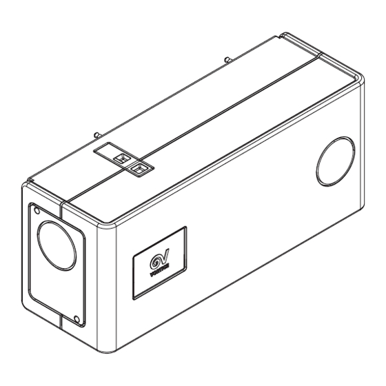
ENGLISH Product description Vort PIV W (hereinafter "the appliance") is a PIV (Positive Input Ventilation) ventilation unit with continuous operation, designed to be installed on the wall in apartments, especially where there is no attic. The appliance introduces into the apartment clean (eventually heated) air, taken from the outside, after particle filtering. Positive inlet ventilation (PIV) by introducing clean air into the apartment, contributes to the reduction of humidity, counteracting the formation of mould, and contributes to the reduction of Radon, if present. -
Page 5: Safety/Warnings
Safety/Warnings • After removing the appliance from its packaging, ensure that it is complete and undamaged. If in doubt contact an authorised Vortice service centre. Do not leave packaging within the reach of children or differently able persons. • Store the appliance out of the reach of children and disabled persons if you decide to disconnect it from the power supply and use it no more. -
Page 6: Configurations
ENGLISH Configurations Two versions of the appliance are available, depending on the direction of the air flow (fig.2,3) Vort PIV W LH Vort PIV W RH In each version it is possible to create the air inlet and outlet using the different vents on the device in various ways: 3 for the air inlet, 2 for the outlet, also simultaneously active (see fig. - Page 7 ENGLISH Side outlet (side view) Air outlet ø 100 mm ø 100 mm RH Version Vort PIV Ext. wall Room Hallway ø 100 mm Frontal outlet (top view) Vort PIV Ext. wall Room Hallway ø 100 mm Side + Frontal outlet (top view) Vort PIV Ext.
-
Page 8: General Warnings For The Installer
ENGLISH General warnings for the installer NOTE: the official document to refer to is: “The Building Regulations: Approved Document F: Volume 1 applies to dwellings”. NOTE: the appliance MUST be mounted in the orientation of the chosen model (RH version, air flow to the right, or LH version, to the left): the version cannot be re-configured to the other version during installation. -
Page 9: Installation
ENGLISH Installation Separate the appliance components as shown in fig 13 The template supplied must be used to drill the holes in the wall, for the 2 wall hooks. There are 2 fixing points for the appliance for the hooks (1, 2 fig 14). The template indicates the position of the holes for the RH and LH model (front and / back side of the template). - Page 10 ENGLISH RH/LH Versions RH/LH Versions RH/LH Versions...
- Page 11 ENGLISH RH Version LH Version mark the position of the 3rd hole on the wall, breaking mark the position of the 3rd through the polypropylene hole on the wall, breaking wall of the appliance with through the polypropylene a drill and a 6 mm bit wall of the appliance with a drill and a 6 mm bit Mark on the wall the...
- Page 12 ENGLISH apply the complete the wall drilling dowel in the hole RH/LH Versions the fused spur must always be an integrated component in the system FUSED SPUR MAINS 220-240V 50/60Hz FUSE FUSE Do the wiring (power supply)
- Page 13 ENGLISH RH Version In case of connection of a wired remote control LH Version In case of connection of a wired remote control...
- Page 14 ENGLISH RH Version screw insert the spacer apply the cap A (supplied) (supplied) hang on the wall LH Version insert the spacer screw apply the cap B (supplied) (supplied) align position RH Version WIRED REMOTE COMMAND MOTOR SIGNAL MOTOR SUPPLY HEATER SUPPLY POWER SUPPLY...
- Page 15 ENGLISH 22 b LH Version WIRED REMOTE COMMAND MOTOR SIGNAL MOTOR SUPPLY HEATER SUPPLY POWER SUPPLY RH Version RF MODELS RF MODULE MOTOR SIGNAL MOTOR SUPPLY HEATER SUPPLY POWER SUPPLY...
- Page 16 ENGLISH 23 b LH Version RF MODELS RF MODULE MOTOR SIGNAL MOTOR SUPPLY HEATER SUPPLY POWER SUPPLY Complete assembly in the number sequence of the components Finally tighten the side panel screws (4x) NOTE Do not apply excessive tightening torque...
-
Page 17: Commissioning
ENGLISH Commissioning When turned on, pressing any key activates the control panel display (after 30 s of inactivity the display switches off saving the current settings). The display has two lines and is accompanied by a 7-key touch keyboard. The initial setting can be performed from the installer menu with the default access password "0000": one of the 4 Normal + Boost speed sets can be selected, according to the following combinations set in the factory (in compliance with the "Building Regulations”) (refer to “Set Speed”... - Page 18 - RADON: this function allows for continuos operation, with the aim of eliminating traces of radon or other pollutants in the loft 24h / 24h. In the RF models there is a radio controller that allows you to connect external radio devices (not Vortice), with which it is possible: - to select normal or boost speed;...
-
Page 19: Use
ENGLISH Meaning of the keys on the keyboard - enter the “edit” mode ENTER - save and exit “edit” mode - shifting selection between the values of a ARROW DX/SX 4 2 3 5 3 2 1 parameter (in user mode “Edit parameters” and installer mode “Service”) - scrolling list of values or list of parameters ARROW UP/DOWN:... - Page 20 ENGLISH TIME Display of the current time. Edit parameters SPEED Press key to enter Edit Mode NORMAL: 13l/s 24° HEATER: AUTO(OFF) Press key to select SPEED parameter NORMAL: 13l/s 24° HEATER: AUTO(OFF) Press key to select the desired value (NORMAL or BOOST) NORMAL: 13l/s 24°...
- Page 21 ENGLISH HEATER Press key to enter Edit Mode NORMAL: 13l/s 24° HEATER: AUTO(OFF) Press key to select HEATER parameter NORMAL: 13l/s 24° HEATER: AUTO(OFF) Press key to select the desired value - AUTO: the heater is switched on or off NORMAL: 13l/s 24°...
- Page 22 ENGLISH Configuration Menu “Service” menu: this is password protected so you will require the Service unit’s password. If this is a new User installation the default passwordis “0000” “User” menu: this is not password protected Service Enter “Configuration Menu” Enter Installer password: default “0000”...
- Page 23 ENGLISH SET SPEED SET SPEED Press key to select the function required 13 l/s 19 l/s SET SPEED 31 l/s 36 l/s NORMAL BOOST Press to confirm selection 19 l/s 25 l/s and Save / Exit 25 l/s 31 l/s 31 l/s 36 l/s Press...
- Page 24 ENGLISH SET QUIET MODE SET QUIET MODE Press key to select the function required (Boost disabled) SET QUIET MODE QUIET FROM QUIET FROM 00:00 00:00 23:00 06:30 Press to confirm selection Press keys to select the start and Save / Exit hour of the quiet mode;...
- Page 25 ENGLISH SET THRESHOLD TEMP SET THRESH. TEMP. Press key to select the function required (input temperature threshold) When the intake air temperature climbs above the set point, thr mormal speed of the appliance increases by 10%. THRESHOLD TEMP. SET THRESH. TEMP. 20 °C THRESHOLD TEMP.
- Page 26 ENGLISH SET SUMMER TEMP Press key to select the function required (summer temperature threshold). The summer temp(erature) setting is the ambient SET SUMMER TEMP. temperature of the air within the loft space which will when reached or exceeded, the PIV unit will go to standby mode until the air temperature within the loft falls below this point.
- Page 27 IMPORTANT: make a note of the required number is reached the password. If the password is press to move to the next slot lost contact your VORTICE and use to select the next dealer for the master password number. Repeat this process until all four slots are full.
- Page 28 ENGLISH User The only user function wich is settable is the time. This is not password protected. Service User Press key to enter the “User” menu SET TIME: SET TIME: SET TIME 00 : 00 17 : 34 Press to confirm selection Press keys to select the and Save / Exit...
-
Page 29: Maintenance And Cleaning
ENGLISH Maintenance and cleaning Before carrying out any maintenance activities, it is necessary to disconnect the appliance from the power supply. Appliance Clean with a vacuum cleaner or with mild water and soap; do not use corrosive detergents. Filters The G3(ISOCoarse 30%) filter on board can be washed in the washing machine and must be replaced after 4/12 months of use (fig.28: G4(ISOCoarse 60%) and F7(ePM2,5 70%) are optionals). -
Page 30: Available Accessories
ENGLISH Available accessories Code Picture Accessory name and description Notes 20.383 FTR G4 PIV W Refer to fig. 28 for filter installation 20.373 FTR F7 PIV W Refer to fig. 28 for filter installation TUBO CONNETTORE 100 MM 46.188 (CONNECTOR PIPE 100 MM) Wiring diagrams Vort PIV W MAINS... - Page 31 ENGLISH Vort PIV W RF MAINS PREHEATER OUT-REM1 PIV unit L1 N1 Main bipolar switch SMOKE / CO detector with NO/NC contact L N N L (for reference only) FUSE box Preheater External sensors C Temp, C Smoke, C HCS (for reference only) RF internal module PE protection earth terminal...
-
Page 32: Troubleshooting
(see "Maintenance" section). covering the filter area. Problems Contact an Authorized VORTICE Service Centre in the temperature Temperature probe failure and proceed to replace the probe. detection 1) Check the threshold value set for “T winter”... -
Page 33: Disposal
ENGLISH Disposal This product complies with Directive 2012/19/EU on the management of waste electrical and electronic equipment (WEEE). The crossed-out wheeled bin symbol on the appliance indicates that, at the end of its useful life, the product must be taken to a specialised company for transport and treatment. This company will take care of the disposal of the various materials making up the product and their subsequent proper recycling. -
Page 34: Informazioni Generali
Prima di installare ed utilizzare il prodotto, leggere attentamente le istruzioni contenute nel presente libretto Vortice Spa non potrà essere ritenuta responsabile per eventuali danni a persone o cose causati dal mancato rispetto delle indicazioni di seguito elencate, la cui osservanza assicurerà invece la durata e l’affidabilità, elettrica e meccanica, dell’apparecchio. -
Page 35: Descrizione Prodotto
4. pannello di controllo con display LCD, nascosto da un coperchio protettivo; 5. interruttore/ricevitore RF (solo modelli RF); Può essere collegato anche un controllore remoto RF (opzionale, non Vortice) (solo modelli RF). Comandi remoti cablati possono essere utilizzati selezionare velocità... -
Page 36: Sicurezza/Avvertenze
Sicurezza/Avvertenze • Dopo aver tolto il prodotto dall’imballo, assicurarsi della sua integrità. Nel dubbio rivolgersi subito ad un Centro Assistenza Tecnica autorizzato Vortice. Non lasciare parti dell’imballo alla portata di bambini o persone diversamente abili. • Riporre l’apparecchio lontano da bambini e da persone diversamente abili nel momento in cui si decide di scollegarlo dalla rete elettrica e di non utilizzarlo più. -
Page 37: Configurazioni
ITALIANO Configurazioni Sono disponibili due versioni dell’apparecchio, a seconda della direzione del flusso d’aria (fig.2,3) Vort PIV W LH Vort PIV W RH In ciascuna versione è possibile realizzare l’entrata e l’uscita dell’aria utilizzando in vari modi le diverse bocchette presenti sull’apparecchio: 3 per l’ingresso dell’aria, 2 per l’uscita, anche contemporaneamente attive (fig. - Page 38 ITALIANO Uscita aria Uscita laterale (vista frontale) ø 100 mm ø 100 mm Versione RH Vort PIV Muro esterno Stanza Corridoio ø 100 mm Uscita frontale (vista dall’alto) Vort PIV Muro esterno Stanza Corridoio Uscita laterale+frontale (vista dall’alto) ø 100 mm Vort PIV External wall Stanza...
-
Page 39: Avvertenze Generali Per L'installatore
ITALIANO Avvertenze generali per l’installatore NOTA: Il documento ufficiale a cui fare riferimento è: “The Building Regulations: Approved Document F: Volume 1 applies to dwellings”. NOTA: l’apparecchio DEVE essere installato con l’orientamento del modello scelto (versione RH con uscita aria a destra, versione LH con uscita aria a sinistra);... -
Page 40: Installazione
ITALIANO Installazione Separare i componenti dell’apparecchio come in fig.13. La dima in dotazione deve essere utilizzata per praticare i fori nel muro, per i 2 ganci. Per l’apparecchio sono previsti 2 punti di fissaggio per i ganci (1, 2 fig 14). La dima indica la posizione dei fori per il modello RH e LH (fronte e retro della dima). - Page 41 ITALIANO Versioni RH/LH Versioni RH/LH Fig.17: NOTA: la vite che si trova nella parte inferiore del gancio a parete può essere utilizzata per eseguire una regolazione fine dell’inclinazione dell’apparecchio, dopo che è stato agganciato al muro. Versioni RH/LH...
- Page 42 ITALIANO Versione RH Versione LH marcare sul muro la posizione marcare sul muro la posizione del 3° foro, sfondando la parete del 3° foro, sfondando la parete in polipropilene dell'apparecchio in polipropilene dell'apparecchio con il trapano e punta 6 mm con il trapano e punta 6 mm Segnare sul muro la posizione dell’apparecchio...
- Page 43 ITALIANO completare la applicare il tassello nel foro foratura del muro Versioni RH/LH la scatola fusibili deve essere sempre un componente integrato nell’impianto SCATOLA FUSIBILE MAINS 220-240V 50/60Hz FUSE Eseguire il cablaggio (alimentazione)
- Page 44 ITALIANO Versione RH In caso di collegamento di comando remoto cablato Versione LH In caso di collegamento di comando remoto cablato...
- Page 45 ITALIANO RH Version avvitare inserire il applicare il tappino A distanziatore (in dotazione) (in dotazione) appendere alla parete LH Version inserire il avvitare applicare il tappino B distanziatore (in dotazione) (in dotazione) allineare la posizione Versione RH COMANDO REMOTO CABLATO SEGNALE MOTORE ALIMENTAZIONE MOTORE ALIMENTAZIONE RISCALDATORE...
- Page 46 ITALIANO 22 b Versione LH COMANDO REMOTO CABLATO SEGNALE MOTORE ALIMENTAZIONE MOTORE ALIMENTAZIONE RISCALDATORE ALIMENTAZIONE MODELLI RF Versione RH MODULO RF SEGNALE MOTORE ALIMENTAZIONE MOTORE ALIMENTAZIONE RISCALDATORE ALIMENTAZIONE...
- Page 47 ITALIANO 23 b Versione LH MODELLI RF MODULO RF SEGNALE MOTORE ALIMENTAZIONE MOTORE ALIMENTAZIONE RISCALDATORE ALIMENTAZIONE Completare il montaggio nella sequanza numerica dei componenti Alla fine fissare le viti dei pannelli laterali (4x) Non applicare una coppia di serraggio eccessiva...
-
Page 48: Prima Attivazione
ITALIANO Prima attivazione All’accensione premendo qualunque tasto si attiva il display del pannello comandi (dopo 30 s di inattività il display si spegne salvando le impostazioni correnti). Il display è a due righe ed è accompagnato da una tastiera touch di 7 tasti. Dal menu dell’installatore con password di accesso di default “0000” è possibile eseguire il settaggio iniziale che prevede che venga selezionato uno dei 4 set di velocità... - Page 49 - RADON: modalità di funzionamento continuo, con l'obiettivo di eliminare tracce di radon o altri inquinanti nell’appartamento, 24h/24h. Nei modelli RF è presente un controllore radio che permette di collegare dispositivi radio esterni (non Vortice), con i quali è possibile: - commutare la velocità...
-
Page 50: Utilizzo
ITALIANO Utilizzo Significato dei tasti della tastiera ENTER - entra in modalità “edit” - salva ed esci dalla modalità “edit” FRECCIA DX/SX - spostamento della selezione tra i valori di un 4 2 3 5 3 2 1 parametro (in fase di modifica parametri utente e modalità... - Page 51 ITALIANO TIME Visualizza l’ora corrente Modifica parametri VELOCITA Premere per entrare in modalità Edit NORMAL: 13l/s 24° HEATER: AUTO(OFF) Premere per selezionare il parametro NORMAL: 13l/s 24° SPEED HEATER: AUTO(OFF) Premere per selezionare il valore (NORMAL or BOOST) NORMAL: 13l/s 24° HEATER: AUTO(OFF) BOOST: 25l/s Premere...
- Page 52 ITALIANO HEATER NORMAL: 13l/s 24° HEATER: AUTO(OFF) Premere per entrare in modalità Edit NORMAL: 13l/s 24° HEATER: AUTO(OFF) Premere per selezionare il parametro HEATER NORMAL: 13l/s 24° HEATER: AUTO(OFF) Premere per selezionare il valore: - AUTO: il riscaldatore viene acceso o spento automaticamente funzione della...
- Page 53 ITALIANO Menu Configurazione Menu “Service”: protetto password. tratta Service un’installazione nuova la password User di default è “0000”. Menu “User”: non protetto da password. Entra nel Menu “Configurazione” Service Service PASSWORD: Immettere la password Installatore: User 0000 default “0000” Funzioni disponibili nel menu Service: - Set speed Premere per scorrere la lista...
- Page 54 ITALIANO SET SPEED SET SPEED Premere per selezionare la funzione 31 l/s 36 l/s SET SPEED 13 l/s 19 l/s Premere per salvare/uscire NORMAL BOOST 19 l/s 25 l/s 25 l/s 31 l/s 31 l/s 36 l/s Premere per scorrere i valori disponibili SPEED ADJUST I valori della velocià...
- Page 55 ITALIANO SET QUIET MODE SET QUIET MODE Premere per selezionare la funzione (Boost disabilitato) QUIET FROM QUIET FROM SET QUIET MODE 00:00 00:00 23:00 06:30 Press to salvare/uscire Premere per selezionare l’orario di inizio della modalità Quiet; quindi premere per spostarsi sui minuti e premere selezionare i minuti.
- Page 56 ITALIANO SET THRESHOLD TEMP SET THRESH. TEMP. Premere per selezionare la funzione (soglia temperatura di ingresso). Quanto la temperatura dell’aria in ingresso supera il valore di soglia la velocità Normal aumenta del 10%. THRESHOLD TEMP. SET THRESH. TEMP. 20 °C THRESHOLD TEMP.
- Page 57 ITALIANO SET SUMMER TEMP Premere per selezionare la funzione. SUMMER TEMP è la soglia di temperatura dell'aria esterna raggiunta o superata la quale l'unità PIV SET SUMMER TEMP. andrà in modalità standby, fino a quando la temperatura non scenderà al di sotto di tale soglia.
- Page 58 Una volta password. caso che si è raggiunto il numero smarrimento contattare desiderato premere rappresentante locale Vortice spostarsi sullo slot successivo e premere per selezionare il numero. Ripetere fino a riempire tutti e quattro gli slots. SET TIME SET TIME...
- Page 59 ITALIANO User L’unica variabile impostabile dall’utente è l’ora.(Funzione non protetta da password). Service User Premere per entrare nel Menu “User” SET TIME: SET TIME: SET TIME 00 : 00 17 : 34 Premere per salvare/uscire. Premere per selezionare NOTA: the clock è in formato 24 l’ora.
-
Page 60: Manutenzione E Pulizia
ITALIANO Manutenzione e pulizia Prima di effettuare qualsiasi attività di manutenzione, è necessario scollegare l'apparecchio dalla rete elettrica. Apparecchio Pulire con un’aspirapolvere o con acqua e sapone; non utilizzare detergenti corrosivi. Filtri Il filtro G3(ISOCoarse 30%) a bordo può essere lavato in lavatrice e va sostituito dopo 4/12 mesi di utilizzo (fig.28: i filtri G4(ISOCoarse 60%) ed F7(ePM2,5 70%) sono accessori opzionali). -
Page 61: Accessori Disponibili
ITALIANO Accessori disponibili Codice Figura Nome e descrizione Note 20.383 FTR G4 PIV W Vedi fig.28 per l’installazione 20.373 FTR F7 PIV W Vedi fig.28 per l’installazione 46.188 TUBO CONNETTORE 100 MM Schemi di collegamento Vort PIV W MAINS PREHEATER OUT-REM1-IN OUT-REM2-IN Unità... - Page 62 ITALIANO Vort PIV W RF MAINS PREHEATER OUT-REM1 Unità PIV L1 N1 Interruttore bipolare principale Rilevatore SMOKE/CO con contatti NO/NC (solo per riferimento) L N N L Scatola fusibili Preriscaldatore Sensori esterni C Temp, C Smoke, C HCS ( solo per riferimento ) Modulo interno RF Messa a terra di protezione LOAD...
-
Page 63: Risoluzione Dei Problemi
Anomalia Possible causa Verifica / Intervento Danneggiamento termostato La temperatura non viene rilevata presente sul riscaldatore. Contattare Centro Assistenza Autorizzato VORTICE. Verificare se è intervenuto Surriscaldamento resistenza del Il riscaldatore il termostato di sicurezza a riarmo manuale. riscaldatore non è funzionante... -
Page 64: Smaltimento
ITALIANO Smaltimento Questo prodotto è conforme alla Direttiva 2012/19/UE riguardante la gestione dei rifiuti di apparecchiature elettriche ed elettroniche (RAEE). Il simbolo del cassonetto barrato riportato sull’apparecchio indica che il prodotto, alla fine della propria vita utile, deve essere conferito ad una impresa specializzata sia per il trasporto che per il trattamento. - Page 67 VORTICE S.p.A. se réserve le droit d'apporter toutes les variations afin d'améliorer ses produits en cours de commercialisation. VORTICE S.p.A. behält sich vor, alle eventuellen Verbesserungsänderungen an den Produkten des Verkaufsangebots vorzunehmen. VORTICE S.p.A. se reserva el derecho a hacer cambios en los productos para su mejora en cualquier momento sin previo aviso. VORTICE S.p.A.
- Page 68 La presente garanzia convenzionale offerta da VORTICE S.p.A., con sede in Strada Cerca 2, Frazione di Zoate, 20067, Tribiano (MI) non pregiudica, pertanto, i diritti dei consumatori che sono previsti dalla Direttiva (UE) 2019/771 (c.d. “direttiva garanzia”) e dalla relativa legislazione nazionale di attuazione e recepimento nei paesi membri della UE (in Italia v.
Need help?
Do you have a question about the Vort PIV W Series and is the answer not in the manual?
Questions and answers