
Related Manuals for Vortice VORT PIV QUADRO


Summary of Contents for Vortice VORT PIV QUADRO
- Page 1 Instruction booklet Libretto istruzioni VORT PIV QUADRO VORT PIV QUADRO RF COD. 5.671.084.215 31/01/2023...
-
Page 2: Table Of Contents
Ventilation unit and equipment....4 VORTICE cannot assume any responsibility for Compliance ......5 damage to property or personal injury resulting Safety/Warnings . -
Page 3: General Informations
Before installing and using the appliance, read the warnings in this manual carefully VORTICE cannot assume any responsibility for damage to property or personal injury resulting from failure to abide by the instructions given in this booklet. -
Page 4: Product Description
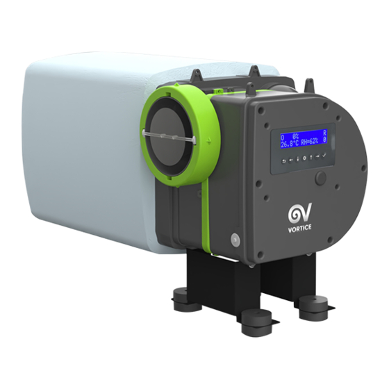
Product description VORT PIV QUADRO is a positive input ventilation unit (PIV) that improves the quality of the air inside a home and helps to resolve problems caused by condensation and mould. It can also be used to control Radon Gas up to certain levels. -
Page 5: Compliance
• After removing the appliance from its packaging, ensure that it is complete and undamaged. If in doubt contact an authorised Vortice service centre. Do not leave packaging within the reach of children or persons with reduced physical, sensory or mental capabilities. -
Page 6: General Warnings For The Installer
- do not allow the unit to be operated by unsupervised children or persons with reduced physical, sensory or mental capabilities. • Should the appliance be dropped or suffer a heavy blow, have it checked immediately by VORTICE. • If the power cord becomes damaged, it must be replaced by the manufacturer or its technical assistance service, or in any case by a person with similar qualifications, in order to prevent any risk. -
Page 7: Installation
ENGLISH Installation • Ceiling diffuser fixing Cut a 200 mm diameter hole in the ceiling in the chosen installation position. Use the template provided if necessary. 1) Mark a circle on the ceiling and cut out the hole using the most suitable tool for each type of ceiling. 2) Mark the holes on the ceiling with a pencil and fix the diffuser group with the plugs, screws and washers supplied. - Page 8 ENGLISH Example of installation of the diffuser (with and without blanking plates) with the relative distances from the fire detector. With blanking plates <1 m Without blanking plates...
- Page 9 ENGLISH • Fixing of the filter onto the ventilation unit G4 filter or optional G4-F7 filter (EPM1 55% - code 20.371) NOX filter optional accessory (code 20.476)
- Page 10 ENGLISH • Fixing of the ventilation unit The installation can be carried out with the unit suspended (e.g. from a convenient roof beam) via the cord supplied, or fixed directly to a suitable surface within the loft by means of the brackets and anti-vibration mounts provided.
- Page 11 ENGLISH 2) Fixing mode with the provided brackets a) Use the 4 triangular fixing points on the bottom of the unit for the installation on the loft floor. (for the installation on the loft ceiling joists please refer to note 3 - fig. 13B). b) Place the fan unit over the brackets.
- Page 12 Note 1: If the insulation on the loft prevents you from mounting the brackets directly on the floor, you can use battens (not provided) on which to fix the brackets (fig.13). Note 2: VORTICE provides as optional accessory an adjustable brackets kit (code 20.460) which allows to install the unit above the loft insulation.
- Page 13 ENGLISH Note 3: The unit can be installed with the brackets fixed to the 4 triangular fixing points on the top of the product and to joists or special battens installed in the loft (fig.13B). Please follow the assembly sequence shown for fixing the brackets to the loft floor (figs. 9-11), making sure to install the brackets in the orientation shown in the figure.
- Page 14 ENGLISH • Installation of the 500 W electric heater (optional - VORTICE code 20.359) a) Fix the electric heater to the diffuser end (fig.15) . b) Fix the flexible hose to the unit and the electric heater. Hose connections can be sealed using proper fixings (not supplied) (fig.
-
Page 15: Wiring
When wiring, the fused spur must always be an integrated component in the system (fig. 17). FUSED SPUR MAINS 220-240V 50/60 Hz FUSE • VORT PIV QUADRO (refer to wiring diagram in fig. 21) WIRING TO WALL SWITCHES WIRING TO ELECTRIC HEATER (NOT PROVIDED) (OPTIONAL) - Page 16 ENGLISH • VORT PIV QUADRO RF (refer to wiring diagrams in fig. 22) WIRING TO THE ELECTRIC HEATER (OPTIONAL)
- Page 17 ENGLISH The fused spur (4) must always be used. L1 N1 The fused spur (4) must LOAD always be used. SUPPLY...
-
Page 18: Available Accessories
Already supplied with the adapter 25.096 sanitizing device. (20.485). ADJUSTABLE BRACKETS KIT 20.460 Refer to fig. 13B VORT PIV QUADRO See “Electic heater” section 20.359 ELECTRIC HEATER 500 PIV under “Operation” menu and specific user manual FTR EPM1 55% G4-F7 20.371... - Page 19 ENGLISH The electric heater should never be mounted directly on the plenum. Fig. 23: example of installation of a PIV unit together with a plenum (in the illustration code 21.324...
-
Page 20: Operation
• VORT PIV QUADRO Automatic functioning VORT PIV QUADRO is designed for continuous operation and it allows the installer to set one of the seven available speed settings. Each setting includes two values: one referred to normal speed and one referred to boost speed. -
Page 21: Commisioning
Once a VORTICE Authorized Service Center has been contacted and the causes of this abnormal overheating have been resolved, the safety thermostat can be manually reset by pressing the key shown in fig. -
Page 22: Use
ENGLISH Normal Normal Boost Boost Absorbed speed Number of bedrooms speed speed speed power Setting airflow (see note 1 /note 2) airflow airflow airflow [l/s] [l/s] (note 4) (note 3) one habitable room 46.8 (Studio) 68.4 118,8 151.2 111.6 133.2 208.8 154.8 10.5... - Page 23 ENGLISH Home screen: switching on the appliance Display parameters Home screen: ACTUAL SPEED, T°C, HEATER STATE On this screen it is displayed: On the first line: - Speed selected normal or boost and corresponding airflow (l/s). Refer to “Set speed” under the “Configuration Menu” for setting the desired speed value.
- Page 24 ENGLISH Edit parameters NORMAL TO BOOST SPEED SELECTION NORMAL: 13l/s 24° NO Heater BOOST: 25l/s 24° BOOST: 25l/s 24° NO Heater NO Heater BOOST: 25l/s 24°C Enter the edit mode by pressing Save and Exit by pressing the the ...
- Page 25 ENGLISH Service User key (5). Then press . To access the service functions, press the Use the & keys to select the numbers of the password. Once the required number is reached press to move to the next slot and use &...
- Page 26 ENGLISH 31 l/s 50 l/s SET SPEED SPEED ADJUST (MENT) The normal (set) speed can be refined by +3l/s to -3 l/s. Note: The normal speed adjustment also affects the corresponding boost speed value with the same increment / decrement. Service menu Use the &...
- Page 27 ENGLISH SET QUIET MODE QUIET FROM 00:00 00:00 SET QUIET MODE Use the & keys to select the start Service menu hour of the quiet mode. Then press to Use the & keys to scroll the move to the minutes and use the ...
- Page 28 ENGLISH SET HEATER MODE When the electric heater is installed the SET HEATER MODE function requires setting to YES to enable the heater function. Service menu Use the & keys to scroll the SET HEATER MODE functions list, press the key to access function required (SET HEATER MODE).
- Page 29 ENGLISH HEATER TEST HEATER DISABLED If the SET HEATER MODE is set to NO (Off) the screen will display “HEATER DISABLED” and then return to the HEATER TEST screen. If the heater is connected go to the “SET HEATER MODE” section. SET THRESH.
- Page 30 ENGLISH SET WINTER TEMP The winter temp(erature) setting is the ambient temperature of the air within the loft space that will switch the post heater ON and OFF . When the loft air temperature falls to or below the set point the post heater switches ON. When the air temperature in the loft climbs above the set point the post heater switches OFF.
- Page 31 NEW PASSWORD: Press the Key twice (4) to return to 2305 main screen. Important Make a note of the password. If the password is lost then contact your VORTICE dealer for the master password. CHANGE PASSWORD...
- Page 32 ENGLISH SET TIME Service menu Use the & keys to scroll the functions list, press the key to access function required (SET TIME). Use the & keys to select the hour. Then press to move to the minuets and use the ...
-
Page 33: Maintenance
ENGLISH Use the & keys to select the hour. Then press to move to the minutes and use the & keys to select the minutes. Press the to confirm selection. And return to service menu screen. Press the Key twice (4) to return to main screen. -
Page 34: Troubleshooting
ENGLISH Battery removal (RF models only) 1) Remove the switch cover panel by hands or by using a screwdriver. 2) Remove the battery cover by means of a flathead screwdriver. 3) Remove the plastic protection and replace the old battery with the new one. 4) Reinstall the battery cover. -
Page 35: Descrizione Del Prodotto
6) Verify that the unit has not been installed in a metal cage because it would be isolated and the radio frequency signal would not reach the receiver. 7) Contact an Authorized VORTICE Service Center Components damaged and request the replacement of the component s (transmitter or receiver... -
Page 36: Disposal
ENGLISH Disposal This product complies with Directive 2012/19/EU on the management of waste electrical and electronic equipment (WEEE). The crossed-out wheeled bin symbol on the appliance indicates that, at the end of its useful life, the product must be taken to a specialised company for transport and treatment. This company will take care of the disposal of the various materials making up the product and their subsequent proper recycling.
Need help?
Do you have a question about the VORT PIV QUADRO and is the answer not in the manual?
Questions and answers