
Subscribe to Our Youtube Channel
Related Manuals for Vortice VORT PIV QUADRO


Summary of Contents for Vortice VORT PIV QUADRO
- Page 1 Instruction booklet Libretto istruzioni VORT PIV QUADRO VORT PIV QUADRO RF COD. 5.671.084.106 16/12/2022...
-
Page 2: Table Of Contents
Ventilation unit and equipment....4 VORTICE cannot assume any responsibility for Compliance ......5 damage to property or personal injury resulting Safety/Warnings . -
Page 3: General Informations
Before installing and using the appliance, read the warnings in this manual carefully VORTICE cannot assume any responsibility for damage to property or personal injury resulting from failure to abide by the instructions given in this booklet. -
Page 4: Product Description
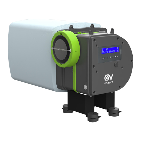
Product description VORT PIV QUADRO is a positive input ventilation unit (PIV) that improves the quality of the air inside a home and helps to resolve problems caused by condensation and mould. It can also be used to control Radon Gas up to certain levels. -
Page 5: Compliance
• After removing the appliance from its packaging, ensure that it is complete and undamaged. If in doubt contact an authorised Vortice service centre. Do not leave packaging within the reach of children or persons with reduced physical, sensory or mental capabilities. -
Page 6: General Warnings For The Installer
- do not allow the unit to be operated by unsupervised children or persons with reduced physical, sensory or mental capabilities. • Should the appliance be dropped or suffer a heavy blow, have it checked immediately by VORTICE. • If the power cord becomes damaged, it must be replaced by the manufacturer or its technical assistance service, or in any case by a person with similar qualifications, in order to prevent any risk. -
Page 7: Installation
ENGLISH Installation • Ceiling diffuser fixing Make a 200 mm diameter hole in the ceiling in the chosen installation position. Use the template provided if necessary. 1) Mark a circle on the ceiling and cut out the hole using the most suitable tool for each type of ceiling. 2) Mark the holes on the ceiling with a pencil and fix the diffuser group with the plugs, screws and washers supplied. - Page 8 ENGLISH Example of installation of the diffuser (with and without blanking plates) with the relative distances from the fire detector. With blanking plates <1 m Without blanking plates...
- Page 9 ENGLISH • Fixing of the filter onto the ventilation unit G4 filter or optional G4+F7 filter (code 20.371) NOX filter optional accessory (code 20.476)
- Page 10 ENGLISH • Fixing of the ventilation unit The installation can be carried out with the unit suspended (e.g. from a convenient roof beam) via the cord supplied, or fixed on the loft base by means of the brackets and anti-vibration mounts provided. 1) Suspended mode a) Use the cord provided to suspend the unit from a hook on a joist of the loft (fig.
- Page 11 ENGLISH 2) Floor-standing mode a) Place the fan unit over the brackets. Use the screws and washers provided to secure the assembly. b) Mark the holes on the loft floor with a pencil. c) Disassamble the unit from the brackets and attach the brackets to the loft floor by placing the anti-vibration mounts above and below each bracket fixing point.
- Page 12 ENGLISH f) Fix the flexible hose to the unit and to the diffuser. Hose connections can be sealed using proper fixings (not supplied). Note: If the insulation on the loft prevents you from mounting the brackets directly on the floor, you can use battens (not provided) on which to fix the brackets (fig.13).
- Page 13 ENGLISH Note: VORTICE provides as optional accessory an adjustable brackets kit (code 20.460) which allows to install the unit above the loft insulation. Adjustable height 210÷320 mm • RF switch installation The switch can be mounted on a wall or fixed to a standard recessed wall box by using two screws (not supplied).
- Page 14 ENGLISH • Installation of the 500 W electric heater (optional - VORTICE code 20.359) a) Fix the electric heater to the diffuser end. b) Fix the flexible hose to the unit and the electric heater. Hose connections can be sealed using proper fixings (not supplied).
-
Page 15: Wiring
When wiring, the fused spur must always be an integrated component in the system. FUSED SPUR MAINS 220-240V 50/60 Hz FUSE • VORT PIV QUADRO (refer to wiring diagram in fig. 21) WIRING TO WALL SWITCHES WIRING TO ELECTRIC HEATER (NOT PROVIDED) (OPTIONAL) - Page 16 ENGLISH • VORT PIV QUADRO RF (refer to wiring diagrams in fig. 22) WIRING TO THE ELECTRIC HEATER (OPTIONAL)
- Page 17 ENGLISH PIV unit Main bipolar switch MAINS PREHEATER OUT-REM1-IN OUT-REM2-IN SMOKE / CO detector with NO/NC contact (for reference only) L1 N1 L N1 L2 N1 L N1 Fused spur Preheater LOAD Boost Remote Switch SUPPLY Preheater Remote Switch External sensor C TEMP / C SMOKE C HCS (for reference only)
-
Page 18: Available Accessories
Already supplied with the adapter 25.096 sanitizing device. (20.485). ADJUSTABLE BRACKETS KIT 20.460 Refer to fig. 13B VORT PIV QUADRO See “Electic heater” section 20.359 ELECTRIC HEATER 500 PIV under “Operation” menu and specific user manual FTR EPM1 55% G4-F7 20.371... - Page 19 ENGLISH The electric heater should never be mounted directly on the plenum. Fig. 23: example of installation of a PIV unit together with a plenum (in the illustration code 21.324...
-
Page 20: Operation
• VORT PIV QUADRO Automatic functioning VORT PIV QUADRO is designed for continuous operation and it allows the installer to set one of the seven available speed settings. Each setting includes two values: one referred to normal speed and one referred to boost speed. -
Page 21: Commisioning
Once a VORTICE Authorized Service Center has been contacted and the causes of this abnormal overheating have been resolved, the safety thermostat can be manually reset by pressing the key shown in fig. -
Page 22: Use
ENGLISH Normal Normal Boost Boost Absorbed speed Number of bedrooms speed speed speed power Setting airflow (see note 1 /note 2) airflow airflow airflow [l/s] [l/s] (note 4) (note 3) one habitable room 46,8 68,4 118,8 151,2 111,6 133,2 208,8 154,8 176,4 266,4... - Page 23 ENGLISH Home screen: switching on the appliance Display parameters Home screen: ACTUAL SPEED, T°C, HEATER STATE On this screen it is visualized: On the first raw: - actual speed (normal or boost mode) and corresponding airflow (l/s). Refer to “Set speed” under the “Configuration Menu” for setting the desired speed value.
- Page 24 ENGLISH Edit parameters NORMAL TO BOOST SPEED SELECTION NORMAL: 13l/s 24° NO Heater BOOST: 25l/s 24° BOOST: 25l/s 24° NO Heater NO Heater BOOST: 25l/s 24°C Enter the edit mode (1) and Save and Exit (3) select the desired value (2). HEATER The unit is supplied without electric heater (on the screen it is displayed as default “NO HEATER”).
- Page 25 ENGLISH Service menu Enter Installer password and press ok button (). PASSWORD: Service 0000 User SET SPEED SET SPEED Select “Set Speed” SPEED ADJUST SET QUIET MODE SET RADON MODE SET HEATER MODE SET THRESH. TEMP. SET WINTER TEMP. SET SUMMER TEMP. RESET FILTER CHANGE PASSWORD SET TIME...
- Page 26 ENGLISH 0 l/s - 2 l/s SPEED ADJUST Save and Exit 3 l/s 2 l/s 1 l/s 1 l/s 2 l/s 3 l/s Select desired value SET QUIET MODE SET QUIET MODE Select “Set Quiet Mode” Select desired value QUIET FROM QUIET FROM SET QUIET MODE 00:00 00:00...
- Page 27 ENGLISH SET HEATER MODE When an electric heater is installed, it is needed to set the heater mode to ON in order to enable or disable the heater. SET HEATER MODE SET HEATER MODE SET HEATER MODE Select “Set heater mode”. Enable (YES) or disable (NO) Save and Exit.
- Page 28 ENGLISH THRESHOLD TEMP. THRESHOLD TEMP. SET THRESH. TEMP. 21 °C 20 °C Select desired value Save and Exit SET WINTER TEMP SET WINTER TEMP. Select “Set Winter Temp” SET WINTER TEMP. WINTER TEMP. WINTER TEMP. 9 °C 8 °C Select desired value Save and Exit SET SUMMER TEMP.
- Page 29 ENGLISH RESET FILTER RESET FILTER Select “Reset Filter” ARE YOU SURE? RESET FILTER ARE YOU SURE? Save and Exit CHANGE PASSWORD CHANGE PASSWORD Select “Change Password” NEW PASSWORD: NEW PASSWORD: CHANGE PASSWORD 0000 2305 Select desired value Save and Exit SET TIME...
-
Page 30: Maintenance
ENGLISH User menu Service User Maintenance The unit does not require any special maintenance other than a periodic general cleaning and the replacement of the filter. Refer to the following table for the recommended filter replacement interval. Max filter (G4) replacement interval Setting (at Normal speed) [Years]** **Filter change interval is purely indicative, depending on environmental pollution condition and usage of Boost... -
Page 31: Troubleshooting
ENGLISH Battery removal (RF models only) 1) Remove the switch cover panel by hands or by using a screwdriver. 2) Remove the battery cover by means of a flathead screwdriver. 3) Remove the plastic protection and replace the old battery with the new one. 4) Reinstall the battery cover. - Page 32 6) Verify that the unit has not been installed in a metal cage because it would be isolated and the radio frequency signal would not reach the receiver. 7) Contact an Authorized VORTICE Service Center Components damaged and request the replacement of the component s (transmitter or receiver...
-
Page 33: Disposal
ENGLISH Disposal This product complies with Directive 2012/19/EU on the management of waste electrical and electronic equipment (WEEE). The crossed-out wheeled bin symbol on the appliance indicates that, at the end of its useful life, the product must be taken to a specialised company for transport and treatment. This company will take care of the disposal of the various materials making up the product and their subsequent proper recycling. -
Page 34: Informazioni Generali
Prima di installare ed utilizzare il prodotto, leggere attentamente le istruzioni contenute nel presente libretto VORTICE S.p.A. non potrà essere ritenuta responsabile per eventuali danni a persone o cose causati dal mancato rispetto delle indicazioni di seguito elencate, la cui osservanza assicurerà invece la durata e l’affidabilità, elettrica e meccanica, dell’apparecchio. -
Page 35: Descrizione Del Prodotto
Oltre al modello base (VORT PIV QUADRO) è disponibile la versione VORT PIV QUADRO RF, con un interruttore a radiofrequenza che permette di selezionare alternativamente la velocità normale o boost. -
Page 36: Conformità D'uso
• In caso di cattivo funzionamento e/o guasto dell'apparecchio rivolgersi subito ad un Centro di Assistenza autorizzato VORTICE e richiedere, per l’eventuale riparazione, l'uso di ricambi originali VORTICE. • Collegare l’apparecchio alla rete di alimentazione solo se la portata dell’impianto è adeguata alla sua potenza massima. -
Page 37: Avvertenze Generali Per L'installatore
- non consentirne l’uso a bambini o persone diversamente abili non sorvegliate. • Se l’apparecchio cade o riceve forti colpi farlo verificare subito presso un Centro di Assistenza Tecnica autorizzato VORTICE. • Se il cavo di alimentazione è danneggiato deve essere sostituito dal costruttore o dal suo servizio assistenza tecnica, o comunque da una persona con qualifica similare, in modo da prevenire qualsiasi rischio. -
Page 38: Installazione
ITALIANO Installazione • Fissaggio diffusore a soffitto Effettuare nella posizione di installazione scelta un foro nel soffitto di diametro pari a 200 mm. Utilizzare, se necessario, la dima di carta fornita. 1) Segnare sul soffitto un cerchio ed effettuare il foro utilizzando lo strumento più adatto alla tipologia di soffitto presente. - Page 39 ITALIANO Esempio di installazione del diffusore (con e senza profili di chiusura) con le relative distanze rilevatore di fumo. Con profili di chiusura <1 m Senza profili di chiusura...
- Page 40 ITALIANO • Fissaggio filtro su unità ventilante Filtro G4 o filtro opzionale G4+F7 (codice 20.371) Filtro NOX Accessorio opzionale (codice 20.476)
- Page 41 ITALIANO • Fissaggio unità di ventilazione L’installazione può essere realizzata con l’apparecchio sospeso (es. appeso a una trave del tetto) tramite la corda in dotazione, oppure fissato a terra, sul pavimento del sottotetto, mediante apposite staffe e antivibranti. 1) Modalità a sospensione a) Utilizzare la corda fornita per sospendere l’unità...
- Page 42 ITALIANO 2) Modalità a pavimento a) Posizionare l’unità ventilante sopra le staffe. Utilizzare viti e rondelle fornite per fissare l’assieme. b) Segnare con una matita i fori sul pavimento. c) Smontare l'unità dalla staffa e fissare le staffe al pavimento del sottotetto posizionando i supporti anti-vibranti sopra e sotto ciascun punto di fissaggio della staffa.
- Page 43 ITALIANO f) Fissare il tubo flessibile sull’unità e sul diffusore. È possibile sigillare le connesioni del tubo utilizzando due fascette (non fornite). Nota: se l’isolamento presente sul sottotetto impedisce di montare le staffe direttamente sul pavimento, è possibile utilizzare dei listelli (non inclusi) su cui fissare le staffe (fig.13).
- Page 44 ITALIANO Nota: VORTICE può fornire come accessorio opzionale un kit staffe regolabili (cod. 20.460) che permette di installare l'unità sopra l'isolamento del soppalco. Altezza regolabile 210÷320 mm • Installazione interruttore a radio frequenza L'interruttore può essere montato a parete o fissato a una normale scatola da incasso a parete utilizzando le due viti (non incluse).
- Page 45 ITALIANO • Installazione del riscaldatore da 500 W (opzionale - codice VORTICE 20.359) a) Fissare la resistenza elettrica sull flangia del diffusore. b) Fissare il tubo flessibile all'unità e al riscaldatore elettrico. I raccordi dei tubi possono essere sigillati utilizzando apposite fascette (non fornite).
-
Page 46: Cablaggio
Quando si effettua il cablaggio, la scatola fusibile deve essere sempre un componente integrato nell’impianto. SCATOLA FUSIBILE RETE 220-240V 50/60 Hz FUSE • VORT PIV QUADRO (vedere schema di fig. 21) CABLAGGIO A INTERRUTTORI A PARETE (NON FORNITI) COLLEGAMENTO RISCALDATORE (OPZIONALE) - Page 47 ITALIANO • VORT PIV QUADRO RF (vedere schema di fig. 22) COLLEGAMENTO AL RISCALDATORE (OPZIONALE)
- Page 48 ITALIANO Unità PIV Interruttore bipolare principale (Mains bipolar switch) MAINS PREHEATER OUT-REM1-IN OUT-REM2-IN Rilevatore SMOKE / CO con contatti NO/NC (solo per riferimento) L1 N1 L N1 L2 N1 L N1 Scatola fusibile Riscaldatore (Preheater) LOAD Interruttore remoto Boost SUPPLY Interruttore remoto riscaldatore Sensore esterno...
- Page 49 ITALIANO Il riscaldatore non deve mai essere montato direttamente sul plenum. Fig. 23: esempio di installazione di una unità PIV insieme ad un plenum (nella figura si fa vedere il plenum 21.324...
-
Page 50: Accessori Disponibili
VORT SANIKIT 400: Adattatore (20.485) fornito 25.096 dispositivo di sanificazione insieme al plenum. ADJUSTABLE BRACKETS KIT 20.460 VORT PIV QUADRO: Riferirsi alla figura 13B kit di staffe regolabili Vedere la sezione dedicata “Riscaldatore” all’interno del ELECTRIC HEATER 500 PIV: 20.359 Riscaldatore da 500 W. -
Page 51: Funzionamento
• VORT PIV QUADRO Funzionamento automatico VORT PIV QUADRO ha un funzionamento in continuo e permette all’installatore di impostare uno tra i sette settaggi di velocità disponibili. Ogni settaggio comprende due valori: uno riferito alla velocità normale e uno riferito alla velocità boost. Una volta avviata, l’unità funziona alla velocità normale. La velocità boost può essere selezionata tramite display o interruttore a parete, se installato (vedere il paragrafo “Utilizzo”). -
Page 52: Prima Attivazione
è salita oltre un valore preimpostato**. Una volta chiamato un Centro Assistenza Autorizzato VORTICE e risolte le cause di questo surriscaldamento anomalo, il termostato di sicurezza può essere ripristinato manualmente premendo illustrato in fig. 24. -
Page 53: Utilizzo
ITALIANO Portata Numero Portata Portata Portata Potenza a velocità a velocità a velocità di camere da letto a velocità assorbita Settaggio normale (vedere nota 1 / nota boost normale boost [l/s] [l/s] (nota 4) (nota 3) solo una stanza 46,8 abitabile 68,4 118,8... - Page 54 ITALIANO Schermata Home: accensione del dispositivo Parametri del display Schermata Home: FLOW (FLUSSO), HEATER (RISCALDATORE) and T°C Questa schermata visualizza la velocità attuale del flusso d’aria (FLOW), la velocità attuale nell’attico e lo stato del riscaldatore (HEATER). campo ‘FLOW’: 3 valori possibili -FLOW: NORM: velocità...
- Page 55 ITALIANO Modifica parametri FLOW (FLUSSO) NORMAL: 13l/s 24° NO Heater BOOST: 25l/s 24° BOOST: 25l/s 24° NO Heater NO Heater BOOST: 25l/s 24°C Entrare in modalità modifica (1) e Salvare e uscire (3) selezionare il valore desiderato (2). HEATER (RISCALDATORE) L’unità...
- Page 56 ITALIANO Menu “Service” (‘Servizio’) Immettere la password dell'installatore e premere il pulsante OK (). PASSWORD: Service 0000 User SET SPEED (selezione del settaggio di velocità) Selezionare “Set Speed” SET SPEED SPEED ADJUST SET QUIET MODE SET RADON MODE SET HEATER MODE SET THRESH.
- Page 57 ITALIANO Selezionare i valori desiderati 0 l/s - 2 l/s SPEED ADJUST Salvare e uscire 3 l/s 2 l/s 1 l/s 1 l/s 2 l/s 3 l/s IMPOSTARE “QUIET MODE” (modalità silenziosa) SET QUIET MODE Selezionare “Set Quiet Mode” QUIET FROM QUIET FROM SET QUIET MODE 00:00 00:00...
- Page 58 ITALIANO IMPOSTARE “HEATER MODE’ (MODALITÀ RISCALDATORE) Quando è installato un riscaldatore, è necessario impostare la modalità riscaldatore su ON al fine di abilitare o disabilitare il riscaldatore. SET HEATER MODE SET HEATER MODE SET HEATER MODE Selezionare “Set heater mode” Abilitare (YES) o disabilitare (NO) Salvare e uscire.
- Page 59 ITALIANO THRESHOLD TEMP. THRESHOLD TEMP. SET THRESH. TEMP. 21 °C 20 °C Selezionare il valore desiderato. Salvare e uscire. IMPOSTARE “WINTER TEMP’ (temperatura invernale) SET WINTER TEMP. Impostare “Winter Temp” SET WINTER TEMP. WINTER TEMP. WINTER TEMP. 9 °C 8 °C Selezionare valore desiderato.
- Page 60 ITALIANO RESET FILTER (RESET FILTRO) RESET FILTER Selezionare “Reset Filter” ARE YOU SURE? RESET FILTER ARE YOU SURE? Salvare e uscire CHANGE PASSWORD (cambio password) CHANGE PASSWORD Selezionare “Change Password”. NEW PASSWORD: NEW PASSWORD: CHANGE PASSWORD 0000 2305 Impostare il valore scelto Salvare e uscire SET TIME...
-
Page 61: Manutenzione
ITALIANO Menu “User” (menu utente) Service User Manutenzione L'unità non richiede particolari interventi di manutenzione se non una periodica pulizia generale e la sostituzione del filtro. Fare riferimento alla tabella seguente per l'intervallo di sostituzione del filtro consigliato. Intervallo massimo di sostituzione del Settaggio filtro (G4) (a velocità... -
Page 62: Risoluzione Problemi
ITALIANO Rimozione batteria (modelli RF) 1) Rimuovere il pannello di copertura dell’interruttore con la mano o utilizzando un cacciavite. 2) Rimuovere il coperchio della batteria servendosi di un cacciavite a testa piatta. 3) Rimuovere la protezione in plastica e sostituire la vecchia batteria con la nuova. 4) Installare nuovamente il coperchio della batteria. - Page 63 7) Contattare un Centro Assistenza Autorizzato Danneggiamento componenti VORTICE e richiedere la sostituzione dei (trasmettitore o ricevitore a bordo componenti solo dopo avere eseguito tutte le macchina) verifiche dal punto 1) al 6).
-
Page 64: Smaltimento
ITALIANO Smaltimento Questo prodotto è conforme alla Direttiva 2012/19/UE riguardante la gestione dei rifiuti di apparecchiature elettriche ed elettroniche (RAEE). Il simbolo del cassonetto barrato riportato sull’apparecchio indica che il prodotto, alla fine della propria vita utile, deve essere conferito ad una impresa specializzata sia per il trasporto che per il trattamento. - Page 65 VORTICE S.p.A. se réserve le droit d'apporter toutes les variations afin d'améliorer ses produits en cours de commercialisation. VORTICE S.p.A. behält sich vor, alle eventuellen Verbesserungsänderungen an den Produkten des Verkaufsangebots vorzunehmen. VORTICE S.p.A. se reserva el derecho a hacer cambios en los productos para su mejora en cualquier momento sin previo aviso. VORTICE S.p.A.
- Page 66 TAGLIANDO INTERVENTO IN GARANZIA CERTIFICATE OF WORK PERFORMED UNDER GUARANTEE COUPON INTERVENTION SOUS GARANTIE DATA INTERVENTO TIMBRO CENTRO ASSISTENZA DATE OF WORK - DATE INTERVENTION STAMP OF TECHNICAL ASSISTANCE CENTRE - CACHET SERVICE APRES-VENTE TAGLIANDO INTERVENTO IN GARANZIA CERTIFICATE OF WORK PERFORMED UNDER GUARANTEE COUPON INTERVENTION SOUS GARANTIE DATA INTERVENTO TIMBRO CENTRO ASSISTENZA...
- Page 67 UK AND IRELAND CONDIZIONI DI GARANZIA CONDITIONS OF WARRANTY VORTICE SPA garantisce i suoi prodotti per 2 anni dalla This guarantee is offered as an extra benefit and does not data dell’acquisto, che deve essere comprovata da affect your legal rights. All electrical appliances produced...
- Page 68 GARANZIA - GUARANTEE - GARANTIE Per poter usufruire della garanzia il cliente deve compilare e rispedire alla VORTICE SPA, entro 8 giorni dall’acquisto, la “Parte 2” del tagliando di garanzia, all’indirizzo e con le modalità in tale parte riportate. DA CONSERVARE La “Parte 1”...
Need help?
Do you have a question about the VORT PIV QUADRO and is the answer not in the manual?
Questions and answers