
Related Manuals for Cincoze CS-100/P2002 Series


Summary of Contents for Cincoze CS-100/P2002 Series
- Page 1 CS-100/P2002 Series User Manual Industrial Panel PC High Performance Sunlight Readable Series Version: V1.40...
-
Page 2: Table Of Contents
2.1 Location of the Switches/Connectors ..................51 2.1.1 Top View ........................51 2.1.2 Bottom View ....................... 52 2.2 Definition of Switches/Connectors ..................53 2.3 Definition of Switches ......................54 2.4 Definition of Connectors ......................57 CS-100/P2002 Series | User Manual... - Page 3 4.3.10 CSM Configuration ....................104 4.3.11 Asmedia SATA Controller Configuration ..............106 4.3.12 USB Configuration ....................107 4.4 Chipset Setup ........................108 4.4.1 System Agent (SA) Configuration ................108 4.4.2 PCH-IO Configuration ....................109 4.5 Security Setup ........................111 CS-100/P2002 Series | User Manual...
- Page 4 4.6 Boot Setup ..........................112 4.7 Save & Exit ..........................113 Chapter 5 Product Application ......................114 5.1 Digital I/O (DIO) application ....................115 5.1.1 Digital I/O Programming Guide ................. 115 5.2 Digital I/O (DIO) Hardware Specification ................123 CS-100/P2002 Series | User Manual...
-
Page 5: Preface
2023/04/14 Copyright Notice © 2018 by Cincoze Co., Ltd. All rights are reserved. No parts of this manual may be copied, modified, or reproduced in any form or by any means for commercial use without the prior written permission of Cincoze Co., Ltd. All information and specification provided in this manual are for reference only and remain subject to change without prior notice. -
Page 6: Declaration Of Conformity
(such as a fuse, battery, etc.), are not warranted. Before sending your product in, you will need to fill in Cincoze RMA Request Form and obtain a RMA number from us. Our staff is available at any time to provide you with the most friendly and immediate service. -
Page 7: Technical Support And Assistance
Limitation of Liability Cincoze’ liability arising out of the manufacture, sale, or supplying of the product and its use, whether based on warranty, contract, negligence, product liability, or otherwise, shall not exceed the original selling price of the product. The remedies provided herein are the customer’s sole and exclusive remedies. -
Page 8: Safety Precautions
11. If the equipment is not used for a long time, disconnect it from the power source to avoid damage by transient overvoltage. 12. Never pour any liquid into an opening. This may cause fire or electrical shock. 13. Never open the equipment. For safety reasons, the equipment should be opened only by CS-100/P2002 Series | User Manual... - Page 9 The equipment has obvious signs of breakage. 14. CAUTION: Danger of explosion if battery is incorrectly replaced. Replace only with the same or equivalent type recommended by the manufacturer. 15. Equipment intended only for use in a RESTRICTED ACCESS AREA. CS-100/P2002 Series | User Manual...
-
Page 10: Package Contents
Intel® Core™ i3-6100U Processor, P-Cap. Touch and 1x PCIe x4 Expansion Slot1x PCIex4 Expansion 12.1" TFT-LCD 1500 nits Sunlight Readable Touch Panel PC with CS-112HC/P2002E-i3-PI Intel® Core™ i3-6100U Processor, P-Cap. Touch and 1x PCI Expansion CS-100/P2002 Series | User Manual... - Page 11 17" TFT-LCD 1500 nits Sunlight Readable Touch Panel PC with Intel® CS-117C/P2002E-i3 Core™ i3-6100U Processor, P-Cap. Touch and 1x Reserved Expansion Slot 17" TFT-LCD 1500 nits Sunlight Readable Touch Panel PC with Intel® CS-117C/P2002E-i3-E4 Core™ i3-6100U Processor, P-Cap. Touch and 1x PCIe x4 Expansion CS-100/P2002 Series | User Manual...
- Page 12 Intel 6th Gen. Core i5-6300U Expandable Fanless Computer, CFM Interface, CDS Interface, 1x PCI Expansion 21.5" TFT-LCD Full HD 16:9 Panel PC with Projected Capacitive Touch CS-W121C/P2002-i3 and Intel 6th Gen. Core i3-6100U Fanless Computer, CFM Interface, CDS Interface CS-100/P2002 Series | User Manual...
- Page 13 Intel 6th Gen. Core i3-6100U Expandable Fanless Computer, CFM Interface, CDS Interface, 1x PCIex4 Expansion 24” TFT-LCD Full HD 16:9 Panel PC with Projected Capacitive Touch CS-W124C/P2002E-i3-PI and Intel 6th Gen. Core i3-6100U Expandable Fanless Computer, CFM Interface, CDS Interface, 1x PCI Expansion CS-100/P2002 Series | User Manual...
-
Page 14: Chapter 1 Product Introductions
Chapter 1 Product Introductions CS-100/P2002 Series | User Manual... -
Page 15: Overview
(9 to 48VDC) and rigorous industrial protections. 1.2 Highlights Sunlight Readable Providing ultra high brightness and high resolution up to CS-100/P2002 Series is suitable for all lighting conditions including direct sunlight. High Performance Powered by Intel® 6th Gen. Core™ Processor U Series, CS-100/P2002 Series Panel PC has greatly increased computing performance and power efficiency. -
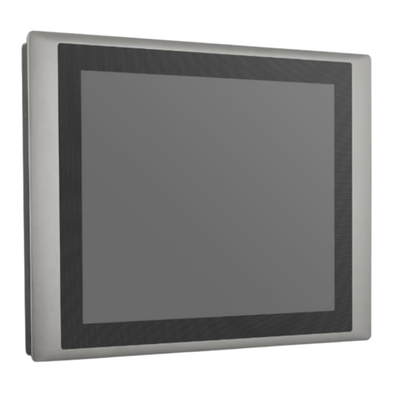
Page 16: Product Pictures
Wide Range Operating Temperature -20°C to 70°C ⚫ Designed with Aluminum Die-casting Front Frame ⚫ True Flat IP65 Front Panel Protection ⚫ Supports Panel / VESA / *Rack Mounting (*with optional mounting kit) ⚫ Convertible Display System (CDS) Technology Supported CS-100/P2002 Series | User Manual... -
Page 17: Hardware Specification
Front Panel Protection • Ambient with Air flow: -20°C to 70°C(extended temperature peripherals) Operating Temperature • -20°C to 70°C Storage Temperature • 80% RH @ 40°C (non-condensing) Relative Humidity • CE, UKCA, FCC, ICES-003 Class A CS-100/P2002 Series | User Manual... - Page 18 2x 2.5” SATA HDD/SSD Bay, Support RAID 0/1 (Gen3) • mSATA 2x mSATA (One Shared by Mini-PCIe Socket) (Gen2) • CFast 1x CFast Socket (Gen3) Expansion PCI Express 1x PCI or 1x PCIex4 Expansion slot • CS-100/P2002 Series | User Manual...
- Page 19 Protection Type: shut down operating voltage, re-power on at the present level to recover • 15A Over Current Protection • +/-8kV (air), +/-4kV (contact) ESD Protection • 2kV Surge Protection • SuperCap Integrated for CMOS Battery Maintenance-free Operation CMOS Battery Backup Operating System CS-100/P2002 Series | User Manual...
- Page 20 • Shock Operating, 50 Grms, Half-sine 11 ms Duration (with SSD, according to IEC60068-2-27) • Vibration Operating, 5 Grms, 5-500 Hz, 3 Axes (with SSD, according to IEC60068-2-64) • CE, UKCA, FCC, ICES-003 Class A CS-100/P2002 Series | User Manual...
- Page 21 Dimensions CS-112H/P2002 Dimensions CS-112HC/P2002E CS-100/P2002 Series | User Manual...
-
Page 22: Cs-115C/P2002 Series
Front Panel Protection • Ambient with Air flow: -20°C to 70°C(extended temperature peripherals) Operating Temperature • -20°C to 70°C Storage Temperature • 80% RH @ 40°C (non-condensing) Relative Humidity • CE, UKCA, FCC, ICES-003 Class A CS-100/P2002 Series | User Manual... - Page 23 2x 2.5” SATA HDD/SSD Bay, Support RAID 0/1 (Gen3) • mSATA 2x mSATA (One Shared by Mini-PCIe Socket) (Gen2) • CFast 1x CFast Socket (Gen3) Expansion PCI Express 1x PCI or 1x PCIex4 Expansion slot • CS-100/P2002 Series | User Manual...
- Page 24 Protection Type: shut down operating voltage, re-power on at the present level to recover • 15A Over Current Protection • +/-8kV (air), +/-4kV (contact) ESD Protection • 2kV Surge Protection • SuperCap Integrated for CMOS Battery Maintenance-free Operation CMOS Battery Backup Operating System CS-100/P2002 Series | User Manual...
- Page 25 • Shock Operating, 50 Grms, Half-sine 11 ms Duration (with SSD, according to IEC60068-2-27) • Vibration Operating, 5 Grms, 5-500 Hz, 3 Axes (with SSD, according to IEC60068-2-64) • CE, UKCA, FCC, ICES-003 Class A CS-100/P2002 Series | User Manual...
- Page 26 Dimensions CS-115C/P2002 CS-115C/P2002E CS-100/P2002 Series | User Manual...
-
Page 27: Cs-117C/P2002 Series
Front Panel Protection • Ambient with Air flow: -20°C to 70°C(extended temperature peripherals) Operating Temperature • -20°C to 70°C Storage Temperature • 80% RH @ 40°C (non-condensing) Relative Humidity • CE, UKCA, FCC, ICES-003 Class A CS-100/P2002 Series | User Manual... - Page 28 2x 2.5” SATA HDD/SSD Bay, Support RAID 0/1 (Gen3) • mSATA 2x mSATA (One Shared by Mini-PCIe Socket) (Gen2) • CFast 1x CFast Socket (Gen3) Expansion PCI Express 1x PCI or 1x PCIex4 Expansion slot • CS-100/P2002 Series | User Manual...
- Page 29 Protection Type: shut down operating voltage, re-power on at the present level to recover • 15A Over Current Protection • +/-8kV (air), +/-4kV (contact) ESD Protection • 2kV Surge Protection • SuperCap Integrated for CMOS Battery Maintenance-free Operation CMOS Battery Backup Operating System CS-100/P2002 Series | User Manual...
- Page 30 • Shock Operating, 50 Grms, Half-sine 11 ms Duration (with SSD, according to IEC60068-2-27) • Vibration Operating, 5 Grms, 5-500 Hz, 3 Axes (with SSD, according to IEC60068-2-64) • CE, UKCA, FCC, ICES-003 Class A CS-100/P2002 Series | User Manual...
- Page 31 Dimensions CS-117C/P2002 CS-117C/P2002E CS-100/P2002 Series | User Manual...
-
Page 32: Cs-119C/P2002 Series
• Ambient with Air flow: -20°C to 70°C(extended temperature peripherals) Operating Temperature • -20°C to 70°C Storage Temperature • 80% RH @ 40°C (non-condensing) Relative Humidity • CE, UKCA, FCC, ICES-003 Class A • UL, cUL, CB Safety CS-100/P2002 Series | User Manual... - Page 33 2x 2.5” SATA HDD/SSD Bay, Support RAID 0/1 (Gen3) • mSATA 2x mSATA (One Shared by Mini-PCIe Socket) (Gen2) • CFast 1x CFast Socket (Gen3) Expansion PCI Express 1x PCI or 1x PCIex4 Expansion slot • CS-100/P2002 Series | User Manual...
- Page 34 Protection Type: shut down operating voltage, re-power on at the present level to recover • 15A Over Current Protection • +/-8kV (air), +/-4kV (contact) ESD Protection • 2kV Surge Protection • SuperCap Integrated for CMOS Battery Maintenance-free Operation CMOS Battery Backup Operating System CS-100/P2002 Series | User Manual...
- Page 35 • Shock Operating, 50 Grms, Half-sine 11 ms Duration (with SSD, according to IEC60068-2-27) • Vibration Operating, 5 Grms, 5-500 Hz, 3 Axes (with SSD, according to IEC60068-2-64) • CE, UKCA, FCC, ICES-003 Class A CS-100/P2002 Series | User Manual...
- Page 36 Dimensions CS-119C/P2002 CS-119C/P2002E CS-100/P2002 Series | User Manual...
-
Page 37: Cs-W121C/P2002 Series
• Ambient with Air flow: 0°C to 70°C(extended temperature peripherals) Operating Temperature • -20°C to 70°C Storage Temperature • 90% RH @ 39°C (non-condensing) Relative Humidity • CE, UKCA, FCC, ICES-003 Class A • UL, cUL, CB Safety CS-100/P2002 Series | User Manual... - Page 38 2x 2.5” SATA HDD/SSD Bay, Support RAID 0/1 (Gen3) • mSATA 2x mSATA (One Shared by Mini-PCIe Socket) (Gen2) • CFast 1x CFast Socket (Gen3) Expansion PCI Express 1x PCI or 1x PCIex4 Expansion slot • CS-100/P2002 Series | User Manual...
- Page 39 Protection Type: shut down operating voltage, re-power on at the present level to recover • 15A Over Current Protection • +/-8kV (air), +/-4kV (contact) ESD Protection • 2kV Surge Protection • SuperCap Integrated for CMOS Battery Maintenance-free Operation CMOS Battery Backup Operating System CS-100/P2002 Series | User Manual...
- Page 40 • Shock Operating, 50 Grms, Half-sine 11 ms Duration (with SSD, according to IEC60068-2-27) • Vibration Operating, 5 Grms, 5-500 Hz, 3 Axes (with SSD, according to IEC60068-2-64) • CE, UKCA, FCC, ICES-003 Class A CS-100/P2002 Series | User Manual...
- Page 41 Dimensions CS-W121C/P2002 CS-W121C/P2002E CS-100/P2002 Series | User Manual...
-
Page 42: Cs-W124C/P2002 Series
• Ambient with Air flow: -20°C to 70°C(extended temperature peripherals) Operating Temperature • -20°C to 70°C Storage Temperature • 80% RH @ 50°C (non-condensing) Relative Humidity • CE, UKCA, FCC, ICES-003 Class A • UL, cUL, CB Safety CS-100/P2002 Series | User Manual... - Page 43 2x 2.5” SATA HDD/SSD Bay, Support RAID 0/1 (Gen3) • mSATA 2x mSATA (One Shared by Mini-PCIe Socket) (Gen2) • CFast 1x CFast Socket (Gen3) Expansion PCI Express 1x PCI or 1x PCIex4 Expansion slot • CS-100/P2002 Series | User Manual...
- Page 44 Protection Type: shut down operating voltage, re-power on at the present level to recover • 15A Over Current Protection • +/-8kV (air), +/-4kV (contact) ESD Protection • 2kV Surge Protection • SuperCap Integrated for CMOS Battery Maintenance-free Operation CMOS Battery Backup Operating System CS-100/P2002 Series | User Manual...
- Page 45 • Shock Operating, 50 Grms, Half-sine 11 ms Duration (with SSD, according to IEC60068-2-27) • Vibration Operating, 5 Grms, 5-500 Hz, 3 Axes (with SSD, according to IEC60068-2-64) • CE, UKCA, FCC, ICES-003 Class A CS-100/P2002 Series | User Manual...
- Page 46 Dimensions CS-W124C/P2002 CS-W124C/P2002E CS-100/P2002 Series | User Manual...
-
Page 47: System I/O
SW: Remote Power On/Off Terminal Block Used to connect to an external speaker Used to connect to remote power on/off switch Mic-in Used to connect to a microphone Used to connect to RS-232/422/485 serial devices CS-100/P2002 Series | User Manual... -
Page 48: Rear
Press to turn-on or turn-off the backlight of display Reset Button - Increase Brightness Used to reset the system Press to increase brightness of the screen - Decrease Brightness Press to decrease brightness of the screen CS-100/P2002 Series | User Manual... -
Page 49: Side (Right)
1.6.4 Side (Right) Antenna Hole Used to connect an antenna for optional Mini-PCIe Used to connect to RS-232/422/485 serial devices WiFi module 1.6.5 Top VESA Mounting Hole These are mounting holes for VESA mount (75x75mm and 100x100mm) CS-100/P2002 Series | User Manual... -
Page 50: Chapter 2 Switches & Connectors
Chapter 2 Switches & Connectors CS-100/P2002 Series | User Manual... -
Page 51: Location Of The Switches/Connectors
2.1 Location of the Switches/Connectors 2.1.1 Top View CS-100/P2002 Series | User Manual... -
Page 52: Bottom View
2.1.2 Bottom View CS-100/P2002 Series | User Manual... -
Page 53: Definition Of Switches/Connectors
SIM1 SIM Card Socket SPK_L1、SPK_R1 Internal Speaker Connector USB2_1 USB 2.0 Port USB3_1、USB3_2 USB 3.0 Port VGA1 VGA Connector PWR_SW1 Power Switch Connector FAN1 FAN Increase DIO1 DIO Connector DIO2 DIO Connector PCIE1 PCIE Connector CS-100/P2002 Series | User Manual... -
Page 54: Definition Of Switches
Clear CMOS Function Setting : Pin Define SW2 Switch Switch mode Function CMOS Clear CMOS Normal (Default) COM1/2 Voltage Function Setting : Pin Define SW2 Switch Switch mode Function ON/ON (Default) COM2 ON/OFF OFF/OFF ON/ON (Default) COM1 ON/OFF OFF/OFF CS-100/P2002 Series | User Manual... - Page 55 OFF/OFF ON/ON (Default) COM4 ON/OFF OFF/OFF ON/ON (Default) COM5 ON/OFF OFF/OFF ON/ON (Default) COM6 ON/OFF OFF/OFF AT_ATX1: AT / ATX Power Mode Switch Definition 1-2 (Left) AT Power Mode 2-3 (Right) ATX Power Mode (Default) CS-100/P2002 Series | User Manual...
- Page 56 BL_PWR1: Backlight Power on / off Switch Definition Push Backlight Power on / off switching BL_UP1: Backlight Increase Switch Definition Push Backlight Increase BL_DN1: Backlight Decrease Switch Definition Push Backlight Decrease RESET1: Reset Switch Switch Definition Push Reset System CS-100/P2002 Series | User Manual...
-
Page 57: Definition Of Connectors
DC power connector to system. LAN1/LAN2: RJ45 with LEDs Port Act LED Definition Link LED Status Definition Status Blinking 1Gbps Network Data Activity Steady Green Yellow Link 100Mbps No Activity Steady Orange Network Link 10Mbps Network Link CS-100/P2002 Series | User Manual... - Page 58 FAN1: External PWM Fan Connector Connector Type: Terminal Block 1X3 3-pin, 3.5mm pitch Definition +12V SENSE Control PWE_SW1: On / Off Switch Definition PWR_SW Do not apply power to this connector! This port is used to connect a SWITCH! CS-100/P2002 Series | User Manual...
- Page 59 CN1: Mini PCI-Express Socket (SIM Card to Link) Pin Definition Pin Definition Pin Definition WAKE# RESERVED +3.3V +3.3V USB_D+ RESERVED PERST# PERN0 +3.3V +1.5V +3.3V CLKREQ# PERN0 RESERVED SIM_DATA +1.5V REFCLK+ SIM_CLK SMB_CLK +1.5V REFCLK+ PETN0 SIM_RESET SMB_DATA PETP0 SIM_VPP +3.3V USB_D- CS-100/P2002 Series | User Manual...
- Page 60 CN2: Mini PCI-Express Socket / mSATA Socket Pin Definition Pin Definition Pin Definition WAKE# +3.3V +3.3V USB_D+ +3.3V PERST# PERN0/SATAPR0 +3.3V +1.5V +3.3VAUX CLKREQ# PERN0/SATARN0 +1.5V REFCLK+ SMB_CLK +1.5V REFCLK+ PETN0 SMB_DATA PETP0 +3.3V USB_D- CS-100/P2002 Series | User Manual...
- Page 61 CN3: mSATA Socket Pin Definition Pin Definition Pin Definition WAKE# +3.3V +3.3V USB_D+ +3.3V PERST# SATARXP +3.3V +1.5V +3.3V SATARXN +1.5V SMB_CLK +1.5V SATATXN SMB_DATA SATATXP +3.3V USB_D- CS-100/P2002 Series | User Manual...
- Page 62 SW2: Set shutdown delay timer when ACC is turned off Pin 1 Pin 2 Pin 3 Pin 4 Definition 0 second 1 minute 5 minutes 10 minutes 30 minutes 1 hour 2 hours Reserved (0 second) CS-100/P2002 Series | User Manual...
-
Page 63: Chapter 3 System Setup
Chapter 3 System Setup CS-100/P2002 Series | User Manual... -
Page 64: Removing Top Cover
3.1 Removing Top Cover Loosen the 6 screws at front and rear panel, then place them aside. Raise the left edge of top cover (1), and raise the other side (2) subsequently to remove it from the chassis. CS-100/P2002 Series | User Manual... -
Page 65: Installing Half Size Mini Pcie Card
Place the top cover aside gently. 3.2 Installing Half Size Mini PCIe Card Locate the Mini PCIe slot. Use provided two screws on bracket to fasten the module and bracket together. CS-100/P2002 Series | User Manual... - Page 66 Tilt the Mini PCIe card at a 45-degree angle and insert it into the socket until the golden finger connector of the card seated firmly. ° Press down the module and use the two screws to fix the module. CS-100/P2002 Series | User Manual...
-
Page 67: Installing Full Size Mini Pcie Card
2. Tilt the Mini PCIe card at a 45-degree angle and insert it to the socket until the golden finger connector of the card seated firmly. 45° 3. Press down the module and use the two screws to fix the module. CS-100/P2002 Series | User Manual... -
Page 68: Installing Msata Card
Locate the mSATA slot on the system board. Tilt the mSATA card at a 45-degree angle and insert it to the socket until the golden finger connector of the card seated firmly. 45° Fasten the card with two screws. CS-100/P2002 Series | User Manual... -
Page 69: Installing Antenna(S)
3.5 Installing Antenna(s) Remove the antenna rubber covers on left and right panel. Penetrate the antenna jack through the hole. Put on the washer and fasten the nut with antenna jack. CS-100/P2002 Series | User Manual... - Page 70 Assemble the antenna and antenna jack together. Attach the RF connector at another end of the cable onto the card. CS-100/P2002 Series | User Manual...
-
Page 71: Installing So-Dimm Memory
2. Tilt the SODIMM module at a 45-degree angle and insert it to SODIMM socket until the gold-pated connector of module contacted firmly with the socket. 3. Press the module down until its fixed firmly by the two locking latches on each side. CS-100/P2002 Series | User Manual... -
Page 72: Installing Pci(E) Card
3.7 Installing PCI(e) Card 1. Locate the retention module of PCI(e) expansion card. 2. Loosen one screw halfway as indicated to have the clamp arm slidable. clamp arm 3. Loosen one screw to remove the PCI bracket. CS-100/P2002 Series | User Manual... - Page 73 5. Fasten one screw to secure the PCI(e) expansion card. 6. Slide the clamp arm of retention module until it contacts the edge of PCI(e) expansion card. CS-100/P2002 Series | User Manual...
-
Page 74: Installing Thermal Pad Of Thermal Block
Place thermal pad on the top of CPU thermal block in order to provide a seamless contact with the body of chassis to create an efficient heat dissipation. Before assembling the system’s chassis cover, please make sure the protective film on the Thermal Pad has been removed! CS-100/P2002 Series | User Manual... -
Page 75: Installing Cfm-Ign Module (Optional)
3.9 Installing CFM-IGN Module (Optional) Locate the power Ignition connector on system motherboard as indicated. Insert the female connector of power ignition board to the male connector on system motherboard. Fasten two screws to secure the power ignition board. CS-100/P2002 Series | User Manual... -
Page 76: Installing Cfm-Poe Module (Optional)
1. Locate the PoE connector on system motherboard as indicated. 2. Insert the female connector of PoE daughter board to the male connector on system motherboard. 3. Fasten two screws to secure the PoE board. CS-100/P2002 Series | User Manual... -
Page 77: Installing Top Cover
3.11 Installing Top Cover 1. Put on the left edge of top cover onto system, and the other side subsequently. 2. Fasten the six screws at front and rear panel to secure the top cover. CS-100/P2002 Series | User Manual... -
Page 78: Installing Sata Hard Drive At Front Panel
1. Turn over the system to bottom side, and remove one screw. 2. Loosen the two screws to remove the HDD bay cover bracket. 3. Pull the rotating arm of HDD bracket outward as indicated. CS-100/P2002 Series | User Manual... - Page 79 5. Place the HDD bracket on screw-hole side of HDD. Use four screws provided to assemble HDD on the bracket. 6. Align the HDD bracket with the entrance of HDD bay. And insert the HDD bracket and push it until the edge connector of HDD fully inserted into SATA slot. CS-100/P2002 Series | User Manual...
-
Page 80: Installing Sata Hard Drive On Bottom Side
7. Put back HDD bay cover at front panel, and fasten it with two screws. 8. Fasten one screw to secure the HDD bracket on the system chassis. 3.13 Installing SATA Hard Drive on Bottom Side Turn over the system to bottom side. Locate the cover of HDD compartment. CS-100/P2002 Series | User Manual... - Page 81 Loosen the two screws, then pull the cover to remove it. Loosen three screws and take the HDD bracket out of HDD compartment. Place the HDD bracket on screw-hole side of HDD. Use four screws provided to assemble HDD on the bracket. CS-100/P2002 Series | User Manual...
- Page 82 Seat the HDD bracket into HDD compartment, and line up the connector of HDD with SATA slot, then push it until HDD is fully connected into slot. Secure the HDD bracket with three screws. Put back the cover and fasten the two screws. CS-100/P2002 Series | User Manual...
-
Page 83: Installing Sim Card
3.14 Installing SIM Card 1. Locate the SIM card slot at front panel. 2. Loosen two screws to remove the cover plate. 3. Insert the SIM card. CS-100/P2002 Series | User Manual... -
Page 84: Installing Cfast Card
1. Locate the CFast card slot at front panel. 2. Loosen the two screws to remove the cover plate. 3. Insert a CFast card until it clicks. 4. Fasten two screws to secure the cover plate. CS-100/P2002 Series | User Manual... -
Page 85: Connecting With Cs Display Module
2. Remove six screws at left and right panel of PC2002. 3. Assemble two mounting brackets to left and right panel of PC2002 by fastening three screws at each side. Left Panel Right Panel CS-100/P2002 Series | User Manual... - Page 86 4. Turn over the system to bottom side. Locate the connector cover of display module. 5. Loosen two screws to remove the cover. The following photos indicates the male connector (on display module) and female connector (on P2002). CS-100/P2002 Series | User Manual...
- Page 87 7. Align the mounting holes of P2000 with the screw holes of display module underneath. Then slide the PC2000 carefully as indicated to have P2002 and display module connected together. 8. Fasten six screws to secure P2002 on the display module. CS-100/P2002 Series | User Manual...
-
Page 88: Installing Vesa Mount
PC to a VESA stand, please fasten eight screws as indicated to fix it on the stand. (Please refer to section 3.16 in this manual for how to attach PC2002 to CV display module.) P2002 + CS display module VESA stand CS-100/P2002 Series | User Manual... - Page 89 CS-100/P2002 Series | User Manual...
-
Page 90: Installing Panel Mount
3.18 Installing Panel Mount 1. Accessories provided by Cincoze are as follows. (Please note that the quantity of mounting kits varies with the size of the display module, please refer to the datasheet for the actual quantity) CS-100/P2002 Series | User Manual... - Page 91 2. All mounting kits displayed are to be inserted into holes. 3. Installation preparation and steps. CS-100/P2002 Series | User Manual...
- Page 92 CS-100/P2002 Series | User Manual...
- Page 93 4. Apply all mount kits to the rest of holes. And you have completed the panel mount installation, as shown below. CS-100/P2002 Series | User Manual...
-
Page 94: Chapter 4 Bios Setup
Chapter 4 BIOS Setup CS-100/P2002 Series | User Manual... -
Page 95: Bios Introduction
( ↑↓ ) to highlight the field and press <Enter> to call up the sub-menu. Then you can use the control keys to enter values and move from field to field within a sub-menu. If you want to return to the main menu, just press the <Esc >. CS-100/P2002 Series | User Manual... -
Page 96: Main Setup
Use arrow keys to move among the items and press <Enter> to accept or enter a sub-menu. 4.2.1 System Date Set the date. Please use <Tab> to switch between date elements. 4.2.2 System Time Set the time. Please use <Tab> to switch between time elements. CS-100/P2002 Series | User Manual... -
Page 97: Advanced Setup
4.3 Advanced Setup 4.3.1 ACPI Settings Enable or disable ACPI Auto Configuration. ■ Enable ACPI Auto Configuration [Enabled] Enables or disables BIOS ACPI Auto Configuration. CS-100/P2002 Series | User Manual... -
Page 98: Amt Configuration
Allows you to enable or disable Intel® Active Management Technology BIOS execution. ■ Un-Configure ME [Disabled] Sets this item to [Disabled] to unconfigure AMT/ME without using a password or set it to [Enabled] to use a password. 4.3.3 PCH-FW Configuration CS-100/P2002 Series | User Manual... -
Page 99: F81866 Super Io Configuration
You can use this screen to select options for the Super IO Configuration, and change the value of the selected option. ■ Serial Port 1~6 Configuration ❑ Serial Port [Enabled] This item will allow users to enable or disable serial port. CS-100/P2002 Series | User Manual... -
Page 100: Hardware Monitor
■ PWM Fan Mode Configuration ❑ PWM Fan1 Duty [60%] This item allows users to change duty cycle value of PWM Fan1. ❑ PWM Fan2 Duty [60%] This item allows users to change duty cycle value of PWM Fan2. CS-100/P2002 Series | User Manual... -
Page 101: S5 Rtc Wake Settings
[Dynamic Time]: Set the increase time from current time to wake system. 4.3.7 Serial Port Console Redirection ■ Console Redirection [Disabled] These items allow users to enable or disable COM0, COM1, COM2, COM3, Com4, COM5 console redirection function. CS-100/P2002 Series | User Manual... -
Page 102: Cpu Configuration
Enables or disables Intel® Virtualization Technology. Virtualization enhanced by Intel® Virtualization Technology will allow a platform to run multiple operating systems and applications in independent partitions. With virtualization, one computer system can function as multiple virtual systems. CS-100/P2002 Series | User Manual... -
Page 103: Sata Configuration
Changes the delay time for option ROM. ❑ HDD Unlock [Enabled] Enables or disables HDD unlock. ❑ LED Locate [Enabled] Enables or disables LED Locate. ❑ Smart Response Technology [[Enabled] Enables or disables Smart Response Technology. ❑ RST Force Form [Disabled] CS-100/P2002 Series | User Manual... -
Page 104: Csm Configuration
Enables or disables SATA Port 1. ❑ Hot Plug [Enabled] Enables or disables Hot Plug support for port1. ■ Serial ATA Port (CFast) ❑ Port 2 [Enabled] Enables or disables SATA Port 2. 4.3.10 CSM Configuration CS-100/P2002 Series | User Manual... - Page 105 This item allows users to select whether to enable the UEFI or legacy option ROM for the other PCI devices. [Do not launch]: Disables option ROM. [UEFI]: Enables UEFI option ROM only. [Legacy]: Enables legacy option ROM only. CS-100/P2002 Series | User Manual...
-
Page 106: Asmedia Sata Controller Configuration
4.3.11 Asmedia SATA Controller Configuration ■ SATA Controller 0 Configuration Settings Displays configuration information on SATA Controller 0. CS-100/P2002 Series | User Manual... -
Page 107: Usb Configuration
Enables or disables support for USB mass storage devices. Determines whether to enable EHCI Hand-off feature for an operating system without EHCI Hand-off support. ■ USB Mass Storage Driver Support Enables or disables support for USB storage devices. CS-100/P2002 Series | User Manual... -
Page 108: Chipset Setup
This item allows users o enable or disable Intel® Virtualization Technology for Directed I/O (VT-d) function. ■ Above 4GB MMIO BIOS assignment [Enabled] This item allows user to enable or disable the Above 4GB Memory Mapped IO BIOS assignment. ■ Graphics Configuration CS-100/P2002 Series | User Manual... -
Page 109: Pch-Io Configuration
PCI Express Root Port (Mini PCIe) ❑ PCI Express Port 5 [Enabled] Allows you to enable or disable PCI Express Port 5. ❑ PCIe Speed [Auto] Allows you to select PCI Express interface speed. Configuration options: [Auto] [Gen1] [Gen2] [Gen3]. CS-100/P2002 Series | User Manual... - Page 110 Allows you to specify which power state system will enter when power is resumed after a power failure. [Last State]: Enter last power state before a power failure. [S0 State]: Enter power-on state. [S5 State]: Enter power-off state. CS-100/P2002 Series | User Manual...
-
Page 111: Security Setup
This section allows users to configure BIOS security settings. 4.5.1 Administrator Password Administrator Password controls access to the BIOS Setup utility. 4.5.2 User Password User Password controls access to the system at boot and to the BIOS Setup utility. CS-100/P2002 Series | User Manual... -
Page 112: Boot Setup
■ New Boot Option Policy [Default] Allows you to change New Boot Option Policy. Configuration options: [Default] [Place First] [Place Last]. ■ Hard Drive BBS Priorities [Default] Allows you to change the order of the legacy devices in the group. CS-100/P2002 Series | User Manual... -
Page 113: Save & Exit
■ Save as User Defaults This item allows you to save the changes done so far as user defaults. ■ Restore User Defaults This item allows you to restore the user defaults to all the options. CS-100/P2002 Series | User Manual... -
Page 114: Chapter 5 Product Application
Chapter 5 Product Application CS-100/P2002 Series | User Manual... -
Page 115: Digital I/O (Dio) Application
This section describes DIO application of the product. The content and application development are better understood and implemented by well experienced professionals or developers. 5.1.1 Digital I/O Programming Guide 5.1.1.1 Pins for Digital I/O of Cincoze P1001 series product Item Standard... - Page 116 0xAA to the index port. Following is an example to enable configuration and to disable configuration by using debug. -o 4e 87 -o 4e 87 (enable configuration) -o 4e aa (disable configuration) 5.1.1.3 Relative Registers To program the F81866A configuration registers, see the following configuration procedures. CS-100/P2002 Series | User Manual...
- Page 117 CS-100/P2002 Series | User Manual...
- Page 118 // Must write twice to enter Extended mode <Select Logic Device> WriteByte(AddrPort, 0x07) WriteByte(dataPort, 0x06) // Select logic device 06h <Input Mode Selection> // Set GP70 to GP77 input Mode WriteByte(AddrPort, 0x80) // Select configuration register 80h CS-100/P2002 Series | User Manual...
- Page 119 // Set (bit 0~7) = 1 to select GP 80 ~87 as Output mode. <Output Value> WriteByte(AddrPort, 0x89) // Select configuration register 89h WriteByte(DataPort, Value) // Set bit 0~7=(0/1) to output GP 80~87 as Low or High <Leave the Extended Function Mode> WriteByte(AddrPort, 0xAA) CS-100/P2002 Series | User Manual...
- Page 120 // Select configuration register 60h WriteByte(DataPort, (ReadByte(DataPort) ǀ 0x03)) WriteByte(AddrPort, 0x61) // Select configuration register 61h WriteByte(DataPort, (ReadByte(DataPort) ǀ 0x20)) <Leave the Extended Function Mode> WriteByte(AddrPort, 0xAA) Note: Cincoze DIO Port base address is 0x0A00h. CS-100/P2002 Series | User Manual...
- Page 121 5.1.1.6 DATA Bit Table (DIO) CS-100/P2002 Series | User Manual...
- Page 122 5.1.1.7 DIO I/O Port Address DI8 DI7 DI6 DI5 DI4 DI3 DI2 DI1 DO8 DO7 DO6 DO5 DO4 DO3 DO2 DO1 Pin Definition Data Bits 0xA03 0xA02 I/O Port address CS-100/P2002 Series | User Manual...
-
Page 123: Digital I/O (Dio) Hardware Specification
DO Signal have to pull up resistor to XCOM+ for external device, the resistance will affect the pull up current Signal High Level: Pull up resistor to XCOM+ Signal Low Level: = XCOM- Sink Current: 1A (Max) CS-100/P2002 Series | User Manual... - Page 124 5.2.1 P2000 DIO Connector Definition DIO1/DIO2 : Digital Input / Output Connector Connector Type: Terminal Block 2X10 10-pin, 3.5mm pitch Definition Definition DC INPUT DC INPUT CS-100/P2002 Series | User Manual...
- Page 125 CS-100/P2002 Series | User Manual...
- Page 126 © 2020 Cincoze Co., Ltd. All rights reserved. The Cincoze logo is a registered trademark of Cincoze Co., Ltd. All other logos appearing in this catalog are the intellectual property of the respective company, product, or organization associated with the logo.
Need help?
Do you have a question about the CS-100/P2002 Series and is the answer not in the manual?
Questions and answers