Table of Contents
Advertisement
Quick Links
Advertisement
Table of Contents

Related Manuals for FALCOM A2D-JP


Summary of Contents for FALCOM A2D-JP
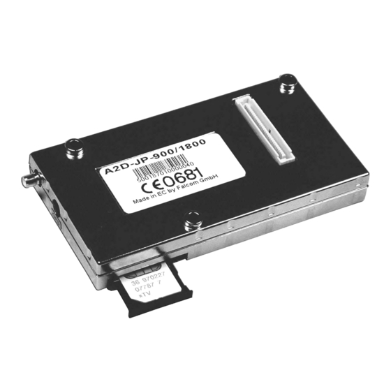
- Page 1 Description Embedded GSM/GPS–Module A2D–JP...
- Page 2 Fal- com Wireless Communications GmbH. All details of FALCOM’s products, particularly those in catalogues, in printed or other form, contain diagrams and details of products and performances which are not gua- ranteed features, but approximations.
-
Page 3: Table Of Contents
Description Contents Contents Introduction......... . 2 General . - Page 4 6.3.5.2 NMEA data message......... . .31 A2D-JP evaluation board ......32 A2D–JP...
- Page 5 Figure 8: The A2D-JP evaluation board ........32...
- Page 6 Description Versions Versions Version number Author Changes V 1.00 M. Menz Initial version V 1.01 G. Buch Chip set of RAM/Flash changed (GPS) V 1.02 G. Buch Reset chip changed (GPS) V 1.03 G. Buch Layout of L2/R35/C2/D13/C27 changed Ground GSM-antenna changed A2D–JP Version 1.03 Side 1...
-
Page 7: Introduction
Introduction General This manual is focussed on the embedded GSM/GPS-module of the FALCOM A2D-JP series from FALCOM GmbH. It contains some information about the FALCOM GSM module and the FALCOM GPS-module based on the CONEXANT Zodiac 2000 chip set. Information furnished herein by FALCOM GmbH is believed to be accurate and reliable. -
Page 8: Figure 2: Technical Drawing Of A2D-Jp
Description Introduction 16.35 13.3 25.5 57.15 53.8±0.15 73.2±0.15 90.2±0.3 (94.7) Figure 2: Technical drawing of A2D–JP A2D–JP Version 1.03 Side 3... -
Page 9: Used Abbreviations
Description Introduction Used abbreviations Abbreviation Meaning Clear To Send signal from Dent DGPS Differential GPS Dilution of Precision ECEF Earth-Centred Earth-Fixed Coordinate system EEPROM Memory for parameter ETSI European Telecommunications Standards Institute Global System for Mobile communications Global Positioning System GPS Fixed Data HDOP Horizontal DOP... -
Page 10: Related Documents
"AT command set for GSM Mobile Equipment" [3] ITU-T V.25ter "Serial asynchronous automatic dialling and control" http:// [4] Zodiac GPS receiver Family Designers' Guide www.falcom.de/service/downloads http:// [5] GPS Chipset-Zodiac 2000 www.falcom.de/service/downloads [6] Serial Data I/O Interface see chapter 5 of [4] Alert symbols used Alerts the user to potential safety risks. -
Page 11: Security
Description Security Security IMPORTANT FOR THE EFFICIENT AND SAFE OPERATION OF YOUR GSM–MODEM, READ THIS INFORMATION BEFORE USE! Your embedded GSM/GPS–modem is one of the most exciting and innovative electronic products ever developed. With it you can stay in contact with your office, your home, emergency services, and others, wherever service is provided. -
Page 12: Efficient Modem Operation
Antennas from other manufacturers which are not authori- zed by the supplier can damage the GPS receiver. Technical modi- fications and additions may contravene local radio-frequency emis- sion regulations or invalidate the type approval. Authorized GPS antennas: FALCOM ANT 006 (active) A2D–JP Version 1.03 Side 7... -
Page 13: Driving
Description Security Driving Check the laws and regulations on the use of cellular devices in the area where you drive. Always obey them. Also, when using your mo- dem while driving, please pay full attention to driving, pull off the road and park before making or answering a call if driving conditions so require. -
Page 14: Blasting Areas
Description Security 2.11 Blasting areas To avoid interfering with blasting operations, turn your unit OFF when in a "blasting area" or in areas posted : „turn off two-way ra- dio“. Construction crew often use remote control RF devices to set off explosives. -
Page 15: Safety Standards
Description Safety standards Safety standards This GSM/GPS-modem complies with all applicable RF safety standards. The embedded GMS/GPS-modem meets the safety standards for RF receivers and the standards and recommendations for the pro- tection of public exposure to RF electromagnetic energy established by government bodies and professional organizations, such as di- rectives of the European Community, Directorate General V in mat- ters of radio frequency electromagnetic energy. -
Page 16: Technical Data
Description Technical data Technical data General specifications Dimensions 95 mm x 50 mm x 15 mm (B x W x H) Weight 60 g Table 2: General specifications Power supply VC3 3.3 V DC ±5 % Max. 190 mA Operate VBAT 3 V DC ±0,25 V Max. -
Page 17: Figure 3: Interface Connections
Description Technical data Figure 3: Interface connections Pin No. 1 Figure 4: Interface A: 60pin connector AMP 177984-2 A2D–JP Version 1.03 Side 12... - Page 18 Description Correction Pin configuration AMP 177984-2 GSM–modem Description Level MIC P15 Microphone 1 positive differential inp. MIC N15 Microphone 1 negative differential inp. SPK P2 Speaker 1 positive differential out. SPK N2 Speaker 1 negative differential out. RS-232 Data Term. Ready CMOS 2,8 V inp.
- Page 19 Description GSM–modem Description Level GROUND SIMPREK SIM present for external card CMOS 2,8 V inp. GROUND SIMDATA SIM Data inp./out. SIMVCC SIM Card power supply 3 V DC SIMRST SIM Reset inp. SIMCLK SIM Clock out. Table 1: Pin configuration AMP 177984-2, GSM-modem GPS receiver Description Level...
-
Page 20: Gsm-Modem
Description GSM–modem GSM–modem General 5.1.1 GSM capability E-GSM and DCS (GSM ETSI Phase I and II) 5.1.2 GSM data services 300 … 14400 BPS, asynchronous, transparent and non-transparent (V.21, V.22, V.23, V.22bis, V.26ter, V.32, V.34, V.110) 5.1.3 RF characteristics Receiver <... -
Page 21: Sim Card Reader
Description GSM–modem 5.1.4 SIM card reader Internal, for small SIM cards (3 V) External, 10 … 15 cm maximum cable length 5.1.5 RS 232 RS 232 2.8 V RX, TX, RTS, CTS, DTR, DSR, DCD, RI Baud rates for serial link (2400 … 19200 with auto-bauding) 300..115200 Table 10: RS 232 5.1.6 Possible external devices... -
Page 22: Figure 5: Gpio 1
Description GSM–modem Pin 30 (EN) This signal is an input of the internal voltage regulator. ❐ Pull to LOW to switch the voltage regulator off (for minimum current consumption). ❐ Pull to HIGH or leave the signal open if EN is not used. Pin 27 (GPIO 1 →... -
Page 23: Figure 6: Sample-Application Simprek
Description GSM–modem DVCC 10 K SIMPRES BC817 100 K SIMPREK Figure 6: Sample-application SIMPREK Pin 16 (RESET GSM) This signal needs to be driven by an external open collector circuit. ❐ To issue a hardware reset pull the signal to LOW for a mini- mum of 100 ms. -
Page 24: Firmware Download Procedure
GSM 07.05. and 07.07. commands The GSM-modem of the FALCOM A2D-JP is controlled by an ad- vanced set of AT-commands. In the following list there is a short overview of these commands. For further information it is recom-... -
Page 25: General At Commands
Description GSM–modem 5.3.1 General AT commands Command Meaning Command Meaning Switch to command mode when con- AT&C1 DCD matches state of the remote nected modem's data carrier Answer call AT&D0 Ignore DTR signal ATDx Dial data number „x“ AT&D1 At DTR-> OFF: Switches from data to command mode ATDx;... -
Page 26: Gsm At Commands (Gsm 07.07)
Description GSM–modem 5.3.3 GSM AT commands (GSM 07.07) Command Meaning Command Meaning AT+CBST Select the bearer type AT+CPIN Enter PIN and query blocks AT+CCFC Control the call forwarding supple- AT+CPWD Change PIN or the supplementary mentary service password AT+CCWA Control the call waiting supplemen- AT+CSQ Display signal quality information tary service... -
Page 27: Gps Receiver
GPS receiver GPS receiver General This description is focussed on the GPS receiver of the FALCOM JP2 series from FALCOM GmbH. It contains some short information about purpose and use of the GPS receiver. The GPS receiver is a single-board 12 parallel channel receiver intended as a component for OEM Products. -
Page 28: Product Overview
Description GPS receiver Product overview The GPS receiver requires conditioned 3,3 V DC power and a GPS signal from a passive or active antenna. The 12 channel architecture provides rapid Time-To-First-Fix (TTFF) under all start-up conditions. As long as visible satellites are not obscured, acquisition is guaranteed under all initialisation con- ditions. -
Page 29: Product Applications
Description GPS receiver Frequency (IF) sampled data to the Scorpio device. The Scorpio de- vice contains an integral microprocessor and all the required GPS- specific signal processing hardware. Memory and other external supporting components configure the GPS receiver into a complete navigation system. -
Page 30: Hardware Interface
Description GPS receiver ❐ Initialised start: is if last known position (in EEPROM) and time are available. Satellite data validity has expired. ❐ Cold start: means only almanac information is used. ❐ Frozen start: no valid internal data source available. Built in test (BIT) mode A BIT is available on command from the application software using binary Message 1300. -
Page 31: Serial Communication Signals
Description GPS receiver In this state, a portion of the GPS receiver's RF circuitry is de-ener- gized, the SRAMs are transitioned into their low power data reten- tion state, and the RTC device is maintained. When the GPS recei- ver is placed into this low power state through the use of the M_RST control signal, the GPS receiver will continue to draw current from the primary input power (PWRIN) but at a reduced level. - Page 32 Description GPS receiver Symbol Parameter Limits (*) Units VOL (min) Minimum low-level output voltage volts VOL (max) Maximum low-level output voltage 0,2 x PWRIN volts tr, tf Input rise and fall time nanoseconds C out Maximum output load capacitance picofarads (*) PWRIN refers to a + 3,3 V DC power input (PWRIN-3) Table 17: Digital signal requirements Pins 49 and 50: host port serial data input and output (SDO1...
-
Page 33: Dc Input Signals
Description GPS receiver If SRAM checksums are invalid and EEPROM checksums are valid, the communication parameters and initialization data parameters will be read from EEPROM. If SRAM checksums are invalid and EEPROM checksums are invalid, the default values in ROM will be used. The OEM application must provide any LD/LR circuitry to extend the range of the interface. -
Page 34: Binary Data Message
Description GPS receiver 6.3.5.1 Binary data message If you wish to use binary data message you get detailed information in [6]. Binary data have more information but are difficult to use. Output message name Default messages Message ID Geodetic position status Position, ground speed, course over ground, climb 1000 rate, map, datum and validity... - Page 35 Description GPS receiver Output message name Default messages Message ID Perform built in test 1300 Restart command With different start condition 1303 Frequency standard Input parame- Is used by GPS without non-volatile storage 1310 ters Power management control 1317 Serial port communication parame- 1330 Message protocol control 1331...
-
Page 36: Nmea Data Message
Description GPS receiver 6.3.5.2 NMEA data message Detailed information shown in [6]. Output message name Default messages Message ID Conexant proprietary Test results for devices Built In test Conexant proprietary Error/status GPS Fix Data Time, position, HDOP GPS DOP and active satellites Operating mode, DOP per coordinate, satellite number GPS satellites in view... -
Page 37: A2D-Jp Evaluation Board
A2D-JP evaluation board A2D-JP evaluation board The quickest way to get first results with the embedded GSM/GPS module is the activation by the A2D-JP evaluation board by means of a terminal program. Figure 8: The A2D-JP evaluation board Figure 8 shows the A2D-JP evaluation board in complete packaging i. - Page 38 So the data of both modules can be processed by your PC at the same time. Thus the evaluation board offers an excellent possibility for develop- ment and testing (trials) of your own application on the base of the embedded GSM/GPS modules A2D-JP. A2D–JP Version 1.03 Side 33...
Need help?
Do you have a question about the A2D-JP and is the answer not in the manual?
Questions and answers