Table of Contents
Advertisement
Quick Links
Advertisement
Table of Contents

Subscribe to Our Youtube Channel
Related Manuals for Graco REGULUS 003.175-DP


Summary of Contents for Graco REGULUS 003.175-DP
- Page 1 USER INFORMATION 6000300E PLEASE KEEP SAFE FOR FUTURE USE Rev. C B.6.50.80-GB ® Diaphragm pump REGULUS GRACO N.V. ® Industrieterrein “Oude Bunders” Loc. 2206 - Slakweidestraat 31 3630 Maasmechelen - Belgium Tel.: 32 89 770 700 Fax: 32 89 770 777...
- Page 2 The original manufacturer’s nameplate is on the diaphragm pump. Please compare the data and supplement if possible. [Translation of nameplate] VERFAHRENSTECHNIK GMBH D-33647 BIELEFELD AIR OPERATED DIAPHRAGM PUMP Model 003.175-DP Production no. Year of construction Material volume flow max.: 114 l/min. Temperature max.: 80 °C Excess pressure max.: 18 bar...
-
Page 3: Table Of Contents
D I A P H R A G M P U M P 0 0 3 . 1 7 5 - D P CONTENTS OF USER INFORMATION Page OPERATING INSTRUCTIONS CORRECT USE FUNCTIONAL DIAGRAM DESCRIPTION OF FUNCTIONS COMPONENT PARTS OF APPLIANCE - IMPORTANT INFORMATION LIST OF TOOLS INSTALLATION COMMISSIONING... -
Page 4: Correct Use
CONTENTS CONTINUED Page TECHNICAL DESCRIPTION OF PRODUCT DESCRIPTION OF DIAPHRAGM PUMP SUITABILITY; MATERIAL TECHNICAL DATA Key to designation Product range; data Sound emission Construction materials used in surface areas in contact with fluid material Dimensions, connection threads, nominal diameters, extensions NOTES LIST OF REPLACEMENT PARTS REPLACEMENT DIAPHRAGM PUMPS, REPLACEMENT ACCESSORIES (Extract from sales... -
Page 5: Functional Diagram
FUNCTIONAL DIAGRAM Compressor Fig. 1 DIAPHRAGM PUMP Pressure tank Safety valve COMPRESSED AIR SUPPLY Pipeline or hose Sound absorber EXHAUST AIR SOUND Pressure regulation valve Vessel SUPPRESSION MATERIAL SUCTION DEVICE Ball cock Suction pipeline MATERIAL PRESSURE Ball cock Pressure pipeline SYSTEM SUPPORT Safety valve... -
Page 6: Component Parts Of Appliance - Important Information
During operation, compressed air escapes into the atmosphere from the propulsion mechanism of the diaphragm pump via the integrated sound absorber . This unburdens it. The material (coating or auxiliary agents) is sucked out of a material receptacle via the suction line by the diaphragm pump and fed on under pressure via the pipe or hose line to the... - Page 7 It goes without saying that the pressure control valve can be situated between the hose line and the compressed air line. The manometer connected 3.1 in function diagram enables exact setting and control of the air pressure required. display range 0 to 16 bar air and local temperature 0 to 50 °C damped construction A shutoff mechanism (e.g.
- Page 8 As there is a connection between sound absorption and the formation of ice on the diaphragm pump control system, the sound level cannot be reduced with a sound absorber as much as would be desired [not < 70 db(A)]. See "Technical Description of Product B.6.50.80-P-GB", page 04 for more detailed information on the sound level.
- Page 9 Temperature of material 10 °C to 85 °C Sieve mesh size 1.8 For a fixed installation the connections diaphragm pump Suction pipe material loop pipe or diaphragm pump pressure tank must be flexible (avoids fracture caused by vibrational stresses). The characteristics of the suction pipe are the same as those for the suction equipment.
- Page 10 Free from materials detrimental to paint use such as silicone. Operational temperature -40 °C to 90 °C or higher. Meets the requirements of all relevant standards (design, identification). The internal hose fittings must be of austenitic stainless steel, outer fittings of galvanised and yellow chromated steel.
-
Page 11: List Of Tools
2 bars are used as wall fixings. This type of fixing Profile sheet is provided for flat walls such as machine walls. A wall fixing made of 2 bars and profile sheets is recommended for uneven walls (brickwork). Fig. 6 Fig. -
Page 12: Installation
INSTALLATION INSTALLATION AND SECURING Diaphragm pumps may only be mounted in a horizontal position (as drawing). Any other position can lead to malfunctioning. The following criteria must be met for a safe fixing: Material pressure line bearing surface and / or wall even and load bearing. Compressed air pipeline dowels and fixing screws must be of sufficient size (Techn. - Page 13 Movable, conducting vessels or appliances which could store an electric charge should also be earthed. The is usually achieved with a flexible connection that is secured, for example, with a clip. Chains may not be used. COMPRESSED AIR SUPPLY The compressor and compressed air storage receptacle (pressure tank) must be of sufficient size - Check thoroughly see also page 5, "Quality of Compressed Air"...
- Page 14 COMPRESSED AIR CONTROL VALVE (PRESSURE CONTROL VALVE), MANOMETER AND BALL COCK see pages 4 and 5 If the pressure control valve is fitted to the diaphragm pump it can be adjusted for easier reading of the manometer. loosen union nut adjust pressure control valve tighten union nut Fig.
-
Page 15: Commissioning
GENERAL ASSEMBLY INSTRUCTIONS Keep to recommended torque. Grease thread lightly. Do not use PTFE tape or hemp. Components not supplied by us must be so dimensioned as to correspond to the given dimensions of the diaphragm pump. - Note manufacturer’s instructions. Observe manufacturer’s assembly instructions when using cutting rings or double conical rings. -
Page 16: Important Information Concerning Commissioning And Operation
- Open pressure control valve. AERATING (BLEEDING) OF APPLIANCE/PLANT Any air remaining in the diaphragm pump or the system must be removed completely. Ensure that the material supply (suction pipe) is immersed in the material. Open the pressure control valve until the diaphragm pump slowly starts. - Operate the diaphragm pump with <... -
Page 17: Operation
Never immerse a running propeller into a filled container. Increase the agitator propeller rotation slowly. Personal safety equipment (breathing apparatus, goggles, gloves, etc.) must be worn when working with material that is dangerous to health. Never point the spraying equipment at people or animals. OPERATION The diaphragm pumps run automatically, i.e. - Page 18 To avoid increased wear and tear of control components through contaminated air a filter is fitted to the compressed air connection of the diaphragm pump. If the stroke frequency decreases over time this should be cleaned. - to clean, simply unscrew compressed air connection with filter.
- Page 19 Always replace both diaphragms. (see breakdown effect analysis, page 22) REPAIR Repairs must be carried out by qualified personnel (experts). (VBG 87). Only our (the manufacturer’s) replacement parts may be used. Our replacement obligation for the pumps and equipment no longer applies if replacement parts other than ours are used (Produkthaftungsgesetz/Product Liability Law of 15 Dec 1989) After dismantling, all parts which are to be reused should be cleaned thoroughly.
- Page 20 REPLACING THE DIAPHRAGMS Remove both housing covers by first removing the appropriate cheese head screws (valve housing, connection parts and casing do not need to be removed). Loosen the diaphragms by hand one after the other and unscrew. If one of the pins rotates during this movement feed an open-ended spanner SW13 under the diaphragm and hold it against the...
- Page 21 If pin is to be removed, first pull out safety rings with flat-nosed pliers. After replacement of wearing parts reassemble in reverse order You will require the gripper (Article No. 70630 002002) to insert the safety rings (special tools, see tool list). To avoid damage to the O-ring, always assemble the pin first, then slide the bushes...
- Page 22 REPLACING THE VALVES Screw out the cheese head screws and remove the connection pieces Remove pressure spring and ball bearing traveller from the valve area. Prise the ball out of the valve seat with the help of a small screwdriver. Feed the pin (special tool) with the thinner shaft through the free valve seat and carefully knock out the valve parts opposite with light taps.
-
Page 23: Torque Moments
TORQUE MOMENTS All screw connections must be tightened so that they comply with the following torque moments. Fig. 18 Position Thread M 10 Torque Moment 12 Nm 10 Nm 6 Nm 8 Nm 15 Nm Table 2 All screw material: 8.8/galvanised DECOMMISSIONING SHORT TERM Cut off the compressed air supply... -
Page 24: Solving Breakdowns
SOLVING BREAKDOWNS Component group Nature of defect Defect symptoms Possible cause Countermeasure Compressed air supply Pump does not start Heavy leakage Defective fitting Replace defective fitting Narrowing of cross section Hose line pinched Check lines Dirty fittings Diaphragm pump Running irregular, Flat slide defective Wear Renew worn parts, check... -
Page 25: Notes
NOTES SELF MONITORING If the 003.175-DP diaphragm pump is operated without monitoring, dangerous situations should be avoided by using automatic self regulation. A stop valve, is particularly suitable for this purpose as it cuts off the compressed air supply to the diaphragm pump if the set limit is exceeded (e.g. -
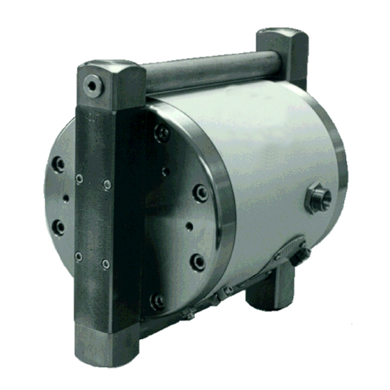
Page 26: Description Of Diaphragm Pump
GRACO D I A P H R A G M P U M P 0 0 3 . 1 7 5 - D P Compressed-air driven double action diaphragm pumps are recommended for coating and process materials D E S C R I P T I O N O F D I A P H R A G M P U M P... -
Page 27: Suitability; Material
S U I T A B I L I T Y , M A T E R I A L T A S K B E H A V I O U R SUITABILITY T R A N S P O R T O F SUITABILITY Transport task Oil, diesel fuel, heating oils,... -
Page 28: Technical Data
T E C H N I C A L D A T A K E Y T O D E S I G N A T I O N D I A P H R A G M P U M P 003 . -
Page 29: Sound Emission
Max. material volume flow l/min (analogous to DIN 24374 T1) Material volume Min. air inlet pressure Max. perm. air inlet pressure Transmission ratio Max perm. excess oper. press. Operational temperature 10-80 ºC Suction height (pump empty) Suction height (device full) When using in paint workshop only silicone-free process material (compressed air) and accessories must be used. -
Page 30: Construction Materials Used In Surface Areas In Contact With Fluid Material
CONSTRUCTION MATERIALS OF SURFACE AREAS IN CONTACT WITH FLUID MATERIAL Pos. Designation Material Pos. Designation Material Valve housing 1.4571 Ball Cover 1.4571 Fixing screw Moulded membrane PTFE/NBR Sealing ring Connector 1.4571 Sealing ring PE-HD Pipe 1.4571 Bush Pressure spring 1.4310 Profile sealing ring PE-HD Ball guide... -
Page 31: Dimensions, Connection Threads, Nominal Diameters, Extensions
DIMENSIONS, SCREW CONNECTION THREADS, NOMINAL DIAMETER OF CONNECTIONS, MOUNTING POSITION Screw plug Pressure connection Fixing thread Earthing clamp Suction connection Fig. 6 Elastic connections Compressed air pipe = 13 Diaphragm pump - compressed air network Material pressure pipe = 25 Diaphragm pump - material container / line Material suction pipe = 25... - Page 32 GRACO D I A P H R A G M P U M P 0 0 3 . 1 7 5 We reserve the right to make amendments Continued on pages 02 to Proc. 22.11.00 Hilse Issued U S E R I N F O R M A T I O N 11.00...
- Page 33 D I A P H R A G M P U M P 0 0 3 . 1 7 5 - D P Replacement part set, diaphragm Article No. 79978 045001 Pos. N u m b e r Designation Moulded diaphragm D 170 O-ring 25 x 2.5 B...
-
Page 34: Notes
REPLACEMENT DIAPHRAGM PUMPS REPLACEMENT ACCESSORIES Diaphragm pumps in basic version Diaphragm pump 003.175-DP - without add-on parts Pos. Material Weight in kg Article No. NIRO (1.4571) 79082 151003 Accessories 1101 1002 1001 1002 1005 1201 See catalogue 07.5001 1007 1202 1006 1002 1008... - Page 35 With the exception of any special, extended, or limited warranty published by Graco, Graco will, for a period of twelve month from the date of sale, repair or replace any part of the equipment determined by Graco to be defective. This warranty applies only when the equipment is installed, operated and maintained in accordance with Graco´s written recommendations.
- Page 36 GRACO N.V. Industrieterrein “Oude Bunders” ® Loc. 2206 - Slakweidestraat 31 3630 Maasmechelen – Belgium Tel.: 32 89 770 700 Fax: 32 89 770 777 We reserve the right to make amendments B.6.50.80-GB / 10.99 / 79990 025029 / D...
Need help?
Do you have a question about the REGULUS 003.175-DP and is the answer not in the manual?
Questions and answers