Table of Contents
Advertisement
Quick Links
Instructions
®
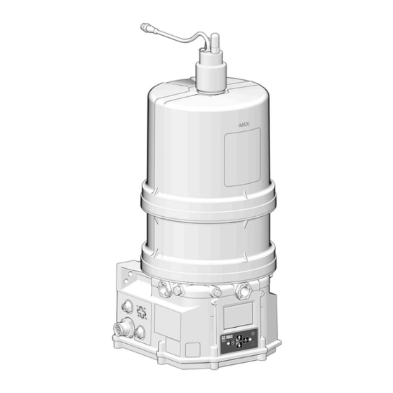
G3
Max Gen 2 Automatic
Lubrication Pump
For dispensing NLGI grades #000 to #2 greases and oils with at least 40cST. For
professional use only.
5100 psi (35.1 MPa, 351.6 bar) Pump Output Pressure
5000 psi (34.5 MPa, 344.7 bar) Fill Inlet Pressure
See page 8 for model information.
IMPORTANT SAFETY INSTRUCTIONS
Read all warnings and instructions in this
manual before using the equipment. Be familiar
with the proper control and usage of the
equipment. Save these instructions.
Related Manuals
Find English manuals and any available translations at
www.graco.com.
English
Manual
Description
Number
333393
Fill Valve
3A1963
Direct Mount Vent Valve for G3 Pumps
3A0533
G3 Pump Element Replacement Kit
For additional support visit https://graco.com/G3Support.
3A9511B
EN
Advertisement
Table of Contents

Subscribe to Our Youtube Channel
Related Manuals for Graco G3 Max Gen 2


Summary of Contents for Graco G3 Max Gen 2
-
Page 1: Related Manuals
Save these instructions. Related Manuals Find English manuals and any available translations at www.graco.com. English Manual Description Number 333393 Fill Valve 3A1963 Direct Mount Vent Valve for G3 Pumps 3A0533 G3 Pump Element Replacement Kit For additional support visit https://graco.com/G3Support. -
Page 2: Table Of Contents
Contents Contents Related Manuals......1 4-Pin (M12) Male Field Wireable Connector for 6 to 8 mm Cable ....27 Safety Symbols . - Page 3 Cellular Connected Pumps ....52 Graco Standard Warranty....84 Initial Cellular Setup .
-
Page 4: Safety Symbols
Safety Symbols Safety Symbols The following safety symbols appear throughout this manual and on warning labels. Read the table below to understand what each symbol means. Symbol Meaning Symbol Meaning Do Not Place Hands or Other Body Cleaning Solvent Hazard Parts Near Fluid Outlet Do Not Stop Leaks with Hand, Electric Shock Hazard... -
Page 5: General Warnings
• Do not kink or over bend hoses or use hoses to pull equipment. • Keep children and animals away from work area. • Comply with all applicable safety regulations. • Only use attachments recommended or sold by Graco. 3A9511B... - Page 6 General Warnings WARNING SKIN INJECTION HAZARD High-pressure fluid from dispensing device, hose leaks, or ruptured components will pierce skin. This may look like just a cut, but it is a serious injury that can result in amputation. Get immediate surgical treatment.
- Page 7 General Warnings WARNING MOVING PARTS HAZARD Moving parts can pinch, cut or amputate fingers and other body parts. • Keep clear of moving parts. • Do not operate equipment with protective guards or covers removed. • Equipment can start without warning. Before checking, moving, or servicing equipment, follow the Pressure Relief Procedure and disconnect all power sources.
-
Page 8: Part / Models Numbers
The Part Number is a six-digit unique number that is only used to order the G3 pump. Directly related to this six-digit Part Number is the configured Graco Model Number. This configured number identifies the distinct features of a specific G3 pump. To help with understanding each component that makes up the Model Number, see Understanding the Model Number, page 10. -
Page 9: 12 Liter Models
Part / Models Numbers 12 Liter Models Part Model Number Number 96G555 G3-G-12M2-120L00-NMCO000VP 96G556 G3-G-24M2-120L00-NMCO000VP 96G557 G3-G-24M2-120L00-RMCD0A0VP 96G558 G3-G-ACM2-120L00-RMCD0A0VP 16 Liter Models Model Number Part Numbers 96G560 G3-G-24M2-160L00-NMCO000VP 96G562 G3-G-ACM2-160L00-RMCD0A0VP 96G599 G3-A-24M2-160A00-RMCD0A0VP 96G600 G3-A-ACM2-160A00-RMCD0A0VP 3A9511B... -
Page 10: Understanding The Model Number
Use the Code Sample to identify each component location in the Model Number. The options for each component that make up the code are provided. NOTE: Other pump configurations are available that are not documented in this manual. Contact Graco Customer Service, or your local Graco distributor for assistance. -
Page 11: Component Identification
= less output volume per stroke) (also see F . 25, Power Cord (not shown) page 29) LCD Display G Fuse (DC models only - Not included, not shown. Level Sensor Available from Graco, see Fuses (DC Models), Top Lid page 16.) Fill Cap (oil models only) 3A9511B... -
Page 12: Typical Installation
Typical Installation Typical Installation . 3: Series Progressive Divider Valve . 4: Injector Installations Key: Connected to fused power source To lube points Pressure relief valve (Required for each pump outlet - Proximity Switch (Divider Installations) - user supplied. See page 17.) - Pressure Switch or Pressure Sensor (Injector Supply Hose (user supplied) Installations) -
Page 13: Reservoir
The installations shown is only a guide for selecting and installing system components and accessories. Contact your Graco distributor for assistance in designing a system to meet your needs. NOTE: The remote filling station pump stalls (dead-heads) when the reservoir is full. If the pump does not stall (dead-heads) there is a leak in the system. -
Page 14: Fill Without Remote Fill Manifold With Auto-Fill Shut Off
The installations shown is only a guide for selecting and installing system components and accessories. Contact your Graco distributor for assistance in designing a system to meet your needs. NOTE: The remote filling station pump stalls (dead-heads) when the reservoir is full. If the pump does not stall (dead-heads) there is a leak in the system. -
Page 15: Installation
• Use designated mounting holes and provided configurations only. The pump module was carefully packaged for shipment by Graco. When the package arrives, perform the fol- • Always mount G3 oil models upright. lowing procedure to unpack the units: •... -
Page 16: System Configuration And Wiring
Fuse Kits are available from Graco. The following Table Improper installation of the grounding conductor may identifies the correct fuse to use for your input voltage result in a risk of electric shock. -
Page 17: Pressure Relief Valves
Installation Pressure Relief Valves Part Description Important Information regarding Pressure Relief VALVE, pressure relief, 500-3500 psi Valve 16C807. (3.44 MPa, 34.4 bar - 24.1 MPa, 241 16C807◆ bar), Set pressure 3000 psi + 10% ◆ Pressure Relief Valve 16C807 can only be used on (20.68 MPa, 206.8 bar + 10%) the G3, or G-Mini Pumps. -
Page 18: Wire And Installation Diagrams
Installation Wire and Installation Diagrams The following table identifies the wiring and installation diagrams provided in this manual. Diagram Symbol Page # Power DIN AC Power DIN DC Power CPC DC Inputs (M12): Cycle Count Machine Count Level Sensor Pressure Sensor Vent Valve Outputs Alarm Outputs Illuminated Manual Run Input... -
Page 19: Power Din Ac - 15 Foot
Installation Power DIN AC - 15 foot Power DIN DC - 15 foot Part No. 2007482 Part No. 16U790 Pin and Related Wire Color (F . 8) Pin and Related Wire Color (F . 7) Pin Name Color Pin Name Color -VDC Black... -
Page 20: Power Cpc Dc - 2 Wire
An Illuminated Remote Run Button kit is used to start a Pin Name Color manual run cycle when used with a 5-wire CPC cable. Kits 571030 and 571031 are available from Graco. Unused Unused Contact your local Graco distributor or Graco Customer... -
Page 21: Power Cpc Dc - 7 Wire
An Illuminated Remote Run Button kit is used to start a manual run cycle when used with a 7-wire CPC cable. Kits 571030 and 571031 are available from Graco. Contact your local Graco distributor or Graco Customer Service for information about these kits. -
Page 22: Inputs (M12), Cycle Count And Machine Count
An Illuminated Remote Run Button kit is used to start a See Technical Specifications, page 81 for ratings. manual run cycle when used with an M12 port. Kit 571033 is available from Graco. Contact your local Graco distributor or Graco Customer Service for information about this kit. -
Page 23: Vent Valve Outputs (M12)
Installation Vent Valve Outputs (M12) Alarm Output See Technical Specifications, page 81 for ratings. DIN Connector Powered Pumps only. See Technical Specifications, page 81 for ratings. . 15 . 16 3A9511B... - Page 24 Installation Level Sensor Input (M12) . 17 3A9511B...
-
Page 25: Pressure Switch/Sensor Input (M12)
Installation Pressure Switch/Sensor Input (M12) . 18 NOTE: The pressure switch should be PNP only. NPN pressure switches are not compatible with the pressure input. 3A9511B... -
Page 26: External Cables
Installation External Cables Cable Pin Out (M12) for 5 m Cable Male Flying Lead Pin Out (M12) Part No. 124333 Part No. 124300 Wire Colors (F . 19) Wire Colors (F . 20) Item No. Color Item No. Color Brown Brown White White... -
Page 27: 4-Pin (M12) Female Field Wireable Connector
Installation 4-Pin (M12) Female Field Wireable 5-Pin (M12) Male Field Wireable Connector Connector for 6 to 8 mm Cable for 8 to 11 mm Cable Part No. 124301 Part No. 124595 . 21 4-Pin (M12) Male Field Wireable Connector . 23 for 6 to 8 mm Cable Part No. -
Page 28: Setup
See Technical Specifications, page 81. • Install a pressure relief valve close to every pump outlet; before any auxiliary fitting. NOTE: A pressure relief valve can be purchased from . 24 Graco, see Pressure Relief Valves, page 3A9511B... -
Page 29: Set Pump Output Volume
Before making any adjustments to pump volume, follow Pressure Relief on page 28. • Only use Graco supplied spacers to control output volume. 1. Use a wrench to turn pump element counter-clock- wise to loosen. Do not remove entire pump ele- . -
Page 30: Models With A Follower Plate
Setup Models Without a Follower Plate Models With a Follower Plate 1. Connect fill hose to Zerk Inlet Fill Fitting (D) 1. Connect fill hose to inlet fitting (D) (F . 27). . 27). 2. For higher viscosity fluids, start pump to rotate stir- ring paddle during fill to prevent air pockets from forming in grease. -
Page 31: Auto-Fill Shut Off
The fill valve is used to relieve pressure in the refill line or greases. and to reset the Auto Fill Shut Off. See Fill Valve instruction manual 333393. Graco fill valve, part no. Remote Fill With Remote Fill Manifold 77X542 is available. Contact your local Graco distribu- tor. -
Page 32: Remote Fill Without Remote Fill Manifold
Typical Installation, starting on page 12. A Pressure Relief Kit: 247902 is available from Graco. Contact your distributor or Graco Customer Service for additional information about this kit. 2. Connect Supply Hose (J) at Quick Connect (V). -
Page 33: Prime The Pump
Setup Prime the Pump Remote Filling Station Pressure Relief The reference letters used in the following instructions NOTE: It is not necessary to prime pump every time refer to F . 6, page 14. pump is filled with lubricant. The following Pressure Relief Procedure is only Pump only requires priming the first time it is used, or if used with the Auto-Fill Shut Off Valve to relieve it is allowed to run dry. -
Page 34: Reservoir Level Monitoring
Setup Reservoir Level Monitoring Low Level Switch (Grease) Level Sensor (Grease Pump) The pump is equipped with a rotating paddle and as the The level transducer continuously monitors the fluid grease level reduces to the minimum level, the paddle level and warns when the follower plate (grease models) momentarily triggers the reed switch (one time per reaches the distance set in the controller programming paddle revolution). -
Page 35: Max Model Set Up
Setup Max Model Set Up Control Panel Overview . 39 3A9511B... -
Page 36: Lcd Screen Details
Setup LCD Screen Details NOTE: Clean with water and soft towel only. . 40 3A9511B... -
Page 37: Program The Max Controller
Setup Program the Max Controller NOTE: Setting changes are not saved until Accept is selected. NOTE: Some pumps have different menu features Lube Mode available, depending on the pump part number. Determines how long and how frequently the pump Navigating Setup and Data Entry lubricates. -
Page 38: Lube End
Setup • Action: Select the action taken (either Lube or Pressure Sensor Mode Alarm) when a machine count interval timeout The lubrication event ends when the system reaches a occurs. specific pressure. This is commonly used with Single Line Parallel (Injector) systems that use a pressure Lube: The lubrication event starts if the target sensor. -
Page 39: Low Level
Setup Low Level Sensor Use with continuous, analog level sensors. The level is The pump stops lubricating when low level is detected. displayed as a percentage (%). Certain types of low level detection methods are avail- able, depending on the pump part number. •... -
Page 40: Start Up
Setup Start Up Signal Outputs (CPC pumps only) Defines the behavior of the pump at power up. Pumps that are configured with CPC power connectors have additional signal outputs available to assist in Enter SETUP then navigate to the START UP menu. monitoring the pump status. -
Page 41: Pulsed Alarm Relay Response
Setup Pulsed Alarm Relay Response Output Tied to Common N.O. Normal Status N.C. N.O. Alert N.C. N.O. Alarm N.C. 1 second Default Remote Illumination, Signal Output, and Relay Alarm Responses The pump has several outputs available that provide information about the system status: •... -
Page 42: Vent Valve
Setup Vent Valve Single Line Parallel (Injector) systems use an external The pump has an LCD display with an integrated vent valve solenoid to control pressure buildup. back-light that can be configured to always remain on, to turn off after a period of inactivity, or to always Some lubrication systems require additional time at remain off. -
Page 43: Program Settings
Sets the response of the pump to the low level float switch as either low level alert or alarm. Level Sensor Type 0.5 to 4.5 V Recommended setting is 0.5-4.5 V for use with a Graco level sensor. Level Sensor Alert Threshold 0 to 99% The alarm threshold must be lower than the alert threshold. -
Page 44: Interval
Setup Interval The interval defines how frequently the pump lubricates. For lubrication systems such as Series Progressive or Single Line Parallel, that have a varied lubrication event duration (due to environmental conditions such as temperature), the pump adjusts the idle time automatically to meet the interval requirements. -
Page 45: Operation
Operation Operation Controller Operation Main Screens Refer to the following illustrations for examples of typical operation screens. . 44 Lubrication Event: Time . 41 Lubrication Event: Pressure Switch . 45 Idle: Timer . 42 Lubrication Event: Pressure Sensor . 46 Idle: Machine Count . -
Page 46: Alerts And Alarms
Operation Alerts and Alarms Additional support on alerts, alarms, and troubleshooting can be found at https://graco.com/G3Support. When the pump has detected an issue with the lubrication system, it may enter an alert or alarm state. During an alert: • The pump continues to operate. -
Page 47: Alert Types
If the lubricant is contaminated or has a high solids content, the pump element may need to be replaced. Replacement pump elements are available from your Graco Lubrication Equipment distributor. Alarm Types See Troubleshooting, page 55 for more information. - Page 48 The vent valve may not be holding pressure. Replace vent valve. To confirm pump operation, check the system pressure at the pump outlet. If the pump does not build pressure, it may need to be repaired or replaced. Replacement pump elements are available from your Graco Lubrication Equipment distributor. 3A9511B...
- Page 49 The pressure relief valve is normally teed into the outlet of the pump element, or incorporated into the vent valve manifold. If no pressure relief valve is installed, contact your Graco Lubrication Equipment distributor to order one, and install as soon as possible,...
- Page 50 The pressure relief valve is normally tied into the outlet of the pump element, or incorporated into the vent valve manifold. If no pressure relief valve is installed, contact your Graco Lubrication Equipment distributor to order one, and install as soon as possible.
-
Page 51: Update Firmware
• Insert a USB drive that contains the latest firmware. The USB drive must be formatted as FAT32. . 50 Only use firmware provided directly from Graco. NOTE: Confirm that the pump settings have not changed after firmware update. •... -
Page 52: Cellular Connected Pumps
Graco Trace website at https://glc.gracotrace.com VERSION INFO. The UID is listed as the RADIO IMEI in using your web browser. this menu. For additional information on how to use Graco Trace, Cloud Configured Pumps access https://graco.com/trace for Graco Trace Graco Trace provides the option to remotely configure supporting information. - Page 53 Operation Series Code Each pump includes a serial label that contains a 6-digit Series Code. The code is used to determine the manufacturing date of the pump. . 52 The table shows the breakdown for the Series Code. Year Code Day Code Series Month Code...
-
Page 54: Maintenance
Maintenance Maintenance Frequency Component Required Maintenance Daily and at refill Zerk Fitting Keep all fittings clean using a clean dry cloth. Dirt and/or debris can damage pump and/or lubrica- tion system. Daily G3 Pump Unit and Reservoir Keep pump unit and reservoir clean using a clean dry cloth. -
Page 55: Troubleshooting
84. Reservoir retaining tabs are cracked Replace reservoirs. If problem per- or broken sists contact your local Graco dis- tributor. Lubricant leaks past seal located on Reservoir is being pressurized during Ensure vent hole is not plugged. - Page 56 Troubleshooting Problem Cause Solution Low ambient temperature Take pump to warmer environment. Display refreshes slowly. This is expected with LCD displays. In injector system, the pressure Set the pressure switch/sensor to switch/sensor is not working the correct pressure. Check the The system is over pressurized and pressure switch/sensor wiring.
-
Page 57: Repair
Repair Repair Remove Power Supply All electrical wiring must be done by a qualified elec- trician and comply with all local codes and regula- tions. Refer to F . 53 for this section. 1. Follow Pressure Relief, page 28 to depressurize the pump. -
Page 58: Replace Power Supply
Repair Replace Power Supply Remove Cellular Board 1. Connect the new power supply (B) to the two locking connectors. 2. Connect the grounding wire screw (D) to the new power supply (B). 3. Place the power supply (B) partially into the pump housing, and place the two screws (A) and slightly tighten. -
Page 59: Replace Cellular Board
Repair Replace Cellular Board Remove Main Board 1. Reconnect the cable interlocking connectors to the cellular board (F). 2. Reconnect the antenna (G) to the cellular module board bracket. NOTE: Be sure to connect to the correct spot or the cell will not work. -
Page 60: Remove Level Sensor
Repair Remove Level Sensor The reservoir needs to be empty for this process. If the reservoir is not empty: 1. On the display, set level sensor type to 0 - 10 V. 2. Disable the Low Level Alert and Alarm features. 3. -
Page 61: Replace Level Sensor
Repair Replace Level Sensor 1. Lubricate the level sensor (M) stem lightly with grease. 2. Replace the level sensor (M) through the top of the block on the reservoir (F . 60). 3. Push the level sensor (M) through the hole in the follower plate (V). -
Page 62: Remove Reservoir With Level Sensor
Repair Remove Reservoir with Level 3. Use a hex key and wrench to loosen and remove fasteners (P, S, and T) (F . 64). Sensor The reservoir needs to be empty for this process. If the reservoir is not empty: 1. - Page 63 Repair NOTE: The reservoir (W) is spring loaded. 5. Position the strap wrench over the reservoir (W) and turn counter-clockwise to remove from the pump base (F . 66). . 66 6. Remove the spring (Y) (F . 67). 7. Remove the follower plate (Z) (F .
-
Page 64: Replace Reservoir With Level Sensor
Repair Replace Reservoir with Level 10. Remove the o-ring (AB) from the adapter ring (B) . 69). Sensor 1. Place new o-ring (AB) on adapter ring (B). . 69 11. Discard all parts. . 70 2. Apply grease to adapter ring (B). 3. - Page 65 Repair 5. Place the new follower plate (Z) onto the stirrer (AC). . 73 6. Apply grease to the follower plate (Z) seal. 7. Place new spring (Y). . 75 8. Put the new reservoir (W) with the level sensor (M) on the base, and align the level sensor (M) rod with 12.
-
Page 66: Remove Reservoir With Level Sensor And Auto-Fill Shut Off (Afso)
Repair Remove Reservoir with Level 3. Use a hex key and wrench to loosen and remove fasteners (P, S, and T) (F . 78). Sensor and Auto-Fill Shut Off (AFSO) The reservoir needs to be empty for this process. If the reservoir is not empty: 1. - Page 67 Repair NOTE: The reservoir (W) is spring loaded. 7. Remove stirrer (AC) by turning clockwise (left hand threaded). 5. Position the strap wrench over the reservoir (W) and turn counter-clockwise to remove from the pump base (F . 80). . 81 8.
-
Page 68: Replace Reservoir With Level Sensor And Auto-Fill Shut Off (Afso)
Repair Replace Reservoir with Level 4. Place the new reservoir with Level Sensor and Auto-Fill Shut Off onto the base (F . 85). Sensor and Auto-Fill Shut OFF (AFSO) 1. Place the new o-ring (AB) on the adapter ring (B . - Page 69 Repair 7. Attach the fastener clip (R) to the level sensor cord (M) (F . 86). . 87 9. Restore power to the pump. 10. On the display, set level sensor type to 0.5 - 4.5 V. 11. Enable the Low Level Alert and Alarm features. 12.
-
Page 70: Parts
Parts Parts G3 Max Gen 2 Pump 2 L Model 3A9511B... - Page 71 Parts G3 Max Gen 2 Pump 2 L Model ▲ Replacement safety labels, tags, and cards are available at no cost. Ref. Part Description ◆ Main controller board kit (PN 2008169) Base, 3 pump housing † Parts included in Kit 571041 (purchase separately)
-
Page 72: G3 Max Gen 2 Pump 4 L And Larger Reservoir
Parts G3 Max Gen 2 Pump 4 L and Larger Reservoir 3A9511B... - Page 73 Parts G3 Max Gen 2 Pump 4 L and Larger Ref. Part Description Reservoir Spring, follower, 8 L models 28✪ Wiper, stirring, 4 L, 8 L follower Ref. Part Description plate models Base, 3 pump housing 29✪ Paddle, stirring, 4 L, 8 L,...
-
Page 74: G3 Max Gen 2 Pump 8 L Reservoir With Auto-Fill Shut Off
Parts G3 Max Gen 2 Pump 8 L Reservoir with Auto-Fill Shut Off 3A9511B... - Page 75 Parts G3 Max Gen 2 Pump 8 L Reservoir with Auto-Fill Shut Off (AFSO) ▲ Replacement safety labels, tags, and cards are Ref. Part Description available at no cost. Base, 3 pump housing ◆ Main controller board kit 2008169 Cover, bottom Screw, mach, torx pan hd, †...
-
Page 76: G3 Max Gen 2 Pump 4 L And 8L Reservoir With Level Sensor And Cellular Connectivity
Parts G3 Max Gen 2 Pump 4 L and 8L Reservoir with Level Sensor and Cellular Connectivity 3A9511B... - Page 77 Parts G3 Max Gen 2 Pump 4 L and 8L Reservoir with Level Sensor and Cellular Connectivity Ref. Part Description Ref. Part Description 35&+✿❖ Lock nut clip level sensor Base, 3 pump housing 36● Power Supply AC Cover, bottom 555888...
-
Page 78: G3 Max Gen 2 Pump 8 L Reservoir With Auto-Fill Shut Off, Level Sensor, And Cellular Connectivity
Parts G3 Max Gen 2 Pump 8 L Reservoir with Auto-Fill Shut Off, Level Sensor, and Cellular Connectivity 3A9511B... - Page 79 Parts G3 Max Gen 2 Pump 8 L Reservoir with Auto-Fill Shut Off, Level Sensor, and Cellular Connectivity Ref. Part Description Ref. Part Description 36■ ^ Washer clip level sensor Base, 3 pump housing 37■ ^ Lock nut clip level sensor Cover, bottom 38●...
-
Page 80: Dimensions
Dimensions Dimensions Mounting Pattern (For correct mounting configuration, choose either Option 1 or Option 2). See P/N 126916 template. Option 1 Option 2 . 88 3A9511B... -
Page 81: Technical Specifications
Technical Specifications Technical Specifications G3 Max GEN 2 Automatic Lubrication Pump Metric Pump output pressure 5100 psi 35.1 MPa, 351.6 bar Auto-Fill Shut Off maximum inlet pressure 5000 psi 34.4 MPa, 344.7 bar Power 100 - 240 VAC 102 VA; 0.85 A / 120 VAC, 0.43A / 240 VAC; 50/60 Hz; single phase 9-16 VDC;... - Page 82 Technical Specifications G3 Max GEN 2 Automatic Lubrication Pump Metric Reservoir Size 2, 4, 8, 12, 16 Ls Sensor Inputs 1 each cycle count, machine count, level sensor, pressure sensor or pressure switch IP Rating IP69K Ambient Temperatures -22°F to 158°F -30°C to 70°C...
-
Page 83: California Proposition 65
Technical Specifications California Proposition 65 CALIFORNIA RESIDENTS WARNING: Cancer and reproductive harm – www.P65warnings.ca.gov. 3A9511B... -
Page 84: Graco Standard Warranty
With the exception of any special, extended, or limited warranty published by Graco, Graco will, for a period of twelve months from the date of sale, repair or replace any part of the equipment determined by Graco to be defective.
Need help?
Do you have a question about the G3 Max Gen 2 and is the answer not in the manual?
Questions and answers