Yaesu FTM-500DR Advance Manual
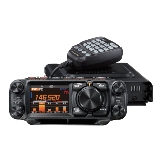
Dual band digital transceiver
Hide thumbs
Also See for FTM-500DR:
- Operating manual (84 pages) ,
- Instruction manual (32 pages) ,
- Manual (13 pages)
Table of Contents
Advertisement
Quick Links
Advertisement
Table of Contents

Related Manuals for Yaesu FTM-500DR


Summary of Contents for Yaesu FTM-500DR
- Page 1 FTM-500DR FTM-500DE...
-
Page 2: Table Of Contents
Contents Digital Personal ID (DP-ID) feature ............ 6 About the Digital Personal ID (DP-ID) feature ............6 Registering the DP-ID to a DR-2X digital repeater ..........6 DR-2X Remote Control Feature ................. 6 Registering the DP-ID of other stations .............. 6 Deleting a registered DP-ID ................ - Page 3 Functions used as needed ............... 23 Timer / Clock function ................... 23 Using the lap timer .................... 23 Using the countdown timer ................24 Using the Voice Guide unit FVS-2 ............... 25 Mounting the voice guide unit “FVS-2” ............. 25 Using the voice memory ..................
- Page 4 MEMORY ........................51 19 HOME CH ......................51 20 MEMORY LIST ....................51 21 MEMORY LIST MODE ..................51 22 PMG.......................51 CONFIG........................52 23 BEEP ......................52 24 BAND SKIP ....................52 25 RPT ARS .......................52 26 RPT SHIFT ....................52 27 RPT SHIFT FREQ ..................52 28 RPT REVERSE .....................53 29 MIC PROGRAM KEY ..................53 30 DATE&TIME ADJUST ...................53 31 DATE&TIME FORMAT ..................53...
- Page 5 GM ..........................61 WIRES-X ........................61 DATA ..........................62 69 COM PORT ....................62 70 DATA BAND ....................63 71 DATA SPEED ....................64 72 DATA SQL ......................65 APRS ..........................66 SD CARD ........................67 107 BACKUP ......................67 108 MEMORY INFO ...................67 109 FORMAT ......................67 OPTION ........................68 111 Bluetooth ......................68 112 VOICE MEMORY ..................68 113 FVS REC .....................68 114 TRACK SELECT..................68...
-
Page 6: Digital Personal Id (Dp-Id) Feature
Digital Personal ID (DP-ID) feature About the Digital Personal ID (DP-ID) feature When operating in digital C4FM communications, each transceiver is programmed with, and sends its own individual ID information (Radio ID) in each transmission. The DP-ID function and the individual identification information, makes possible group communica- tions between stations that are within communications range. - Page 7 DP-ID. Registration When a signal from the other station is received, the : YAESU call sign and “Registration” are displayed on the LCD. • When a signal from another registered transceiver is received, nothing is displayed on the LCD.
-
Page 8: Deleting A Registered Dp-Id
2 JH1YPC 3. Press the SUB DIAL knob. DELETE? : YAESU Confirmation screen “DELETE?” is displayed. 4. Rotate the SUB DIAL knob to select [OK] then press the SUB DIAL knob to delete. • If not deleting in the DP-ID list, select [CANCEL] then press the SUB DIAL knob. -
Page 9: Communicating With Specified Stations In The Analog Fm Mode
Communicating with specified stations in the Analog FM mode Selecting the squelch type in the analog FM mode 1. Press the FUNC knob [SQL] Press the FUNC KEYPAD HOME CH knob or press and hold the FUNC knob [45 SQL SCAN TXPWR HIGH... -
Page 10: Tone Squelch Feature
• The squelch type may be set for each frequency band (BAND). • The CTCSS and DCS squelch settings are also active during scanning. If scanning is performed with the CTCSS and DCS squelch function activated, scanning stops only when a signal containing the specified CTCSS tone or DCS code is received. • Pressing the program key on the microphone to which the “SQL OFF”... -
Page 11: Digital Code Squelch (Dcs) Feature
Digital Code Squelch (DCS) feature The Digital Code Squelch opens the speaker audio only when a signal containing the spec- ified DCS code is received. The DCS code may be selected from 104 types (from 023 to 754). The DCS Squelch does not function in digital mode. Press the [DX] key to change from Digital to Analog FM or AMS mode. -
Page 12: New Two-Tone Ctcss Pager Function
New Two-Tone CTCSS Pager Function When using FTM-500DR/DE transceivers with a group of friends, setting the Two-Tone CTCSS personal codes allows calling just the specific stations. Even when the person who is called is not near the transceiver, the information on the LCD indicates that a call was received. -
Page 13: Receiving "Pager Code" Calls From A Remote Station (Standby Operation)
11. Rotate the FUNC knob to select [TX CODE 2] then press the FUNC knob. 12. Rotate the FUNC knob to select the TX CODE 2 of the codes from 01 to 50. The same code cannot be used for TX CODE 1 and TX CODE 2. 13. -
Page 14: Convenient Memory Function
Convenient memory function Programmable Memory Channel Scan (PMS) Registering to the Programmable Memory Channels 50 sets of PMS memory channels (L01/U01 to L50/U50) are available. • Register the lower and upper frequencies of the frequency range in a pair of Pro- grammable Memory Channels. -
Page 15: Receiving Weather Broadcast Channels
This “WX” function can only be utilized when it is assigned to a programmable key [P1] to [P4] on the microphone. In the USA version of FTM-500DR, “WX” function is assigned to P4 by factory setting. Assigning the “WX” function to a programmable key on the microphone 1. -
Page 16: Dtmf Operation
DTMF Operation DTMF (Dual Tone Multi Frequencies) are the tone signals sent to make telephone calls, or control repeaters and network links. Up to 10 registers of 16-digit DTMF tone codes can be stored as telephone numbers to make calls through the public telephone network using a phone patch or to connect through the WIRES-X analog node station. -
Page 17: Using The Gps Function
Refer to the separate “Operating Manual APRS Edition” Positioning Using GPS The built-in GPS receiver function is enabled when the power of the FTM-500DR/DE is turned ON. The satellite search will begin and the “ ” icon will be shown at the top of the display. -
Page 18: Smart Navigation Function
2. Rotate the FUNC knob to select [BACKTRACK] then press the FUNC knob. The distance and direction to the remote station operating on the same frequency in the V/D mode are displayed. YAESU Callsign of other station Direction to the other station... - Page 19 z Using the Back Track Function 1. In the Real-Time Navigation screen, press the SUB DIAL knob. 2. Rotate the SUB DIAL knob to select the mark ([«], [L1] or [L2]) to register the location information for back tracking. Marks for which location information has not been registered are displayed in gray. 3.
-
Page 20: Saving Gps Information (Gps Log Function)
Using the saved data, tracks can be displayed on a computer with commercially available map software*. * Technical support for the map software is not provided by YAESU. 1. Press and hold the FUNC knob [39 GPS LOG] Press the FUNC knob 2. -
Page 21: Gps Screen Information And Operation
GPS Screen Information and Operation Activating the GPS function presents the following information on the display. 1. Press and hold the FUNC knob [7 DISPLAY MODE] Press the FUNC knob 2. Rotate the FUNC knob to select [GPS INFORMATION] then press the FUNC knob. Azimuth and elevation ③... -
Page 22: Measuring The Altitude
Measuring the altitude The changes in the altitude of the current position and the distance traveled can be displayed on a graph. 1. Press and hold the FUNC knob [7 DISPLAY MODE] Press the FUNC knob 2. Rotate the FUNC knob to select [ALTITUDE] then press the FUNC knob. -
Page 23: Functions Used As Needed
Functions used as needed Timer / Clock function 1. Press and hold the FUNC knob [7 DISPLAY MODE] Press the FUNC knob 2. Rotate the FUNC knob to select [TIMER/CLOCK] then press the FUNC knob. The Clock screen will be displayed. 3. -
Page 24: Using The Countdown Timer
Using the countdown timer 1. In the Timer/Clock function screen, press the SUB DIAL knob. 2. Rotate the SUB DIAL knob to select [MODE] then press the SUB DIAL knob several times to display the count down timer screen. z Set the timer 1. -
Page 25: Using The Voice Guide Unit Fvs-2
Using the Voice Guide unit FVS-2 The receive audio can be recorded and then played back later using the optional voice guide unit “FVS-2”. The frequency of the operating band can also be announced by voice when the announce function is set to ON. Mounting the voice guide unit “FVS-2”... -
Page 26: Using The Voice Memory
7. Refer to the figure on the right to mount the FVS-2. Check the direction of the connector and plug the FVS-2 in all the way to the back. 8. Plug in the speaker cables extending from the main body top cover to the original connector on the board. 9. -
Page 27: Recording The Receive Audio
Recording the receive audio 1. Press and hold the FUNC knob [113 FVS REC] Press the FUNC knob The recording will be started. 2. Rotate the FUNC knob to select [116 FVS STOP], then press the FUNC knob. The recording will stop. -
Page 28: Voice Announcement Of The Operating Frequency
Voice announcement of the operating frequency Setting the announce function operation Set the following voice announcement parameters: • Automatically announce the frequency or not • Announce out the frequency in English or Japanese • Voice announcement audio level • Mute the receive audio during a voice announcement. 1. -
Page 29: Voice Announcement Of The Operating Frequency
Voice announcement of the operating frequency (1) When the voice announcement is set to “AUTO” The frequency of the operating band will be automatically announced in the following cases: • When the VFO mode and memory mode are switched. • When the operating band is changed. (2) When the voice announcement is set to “MANUAL”... -
Page 30: Copying The Radio Data To Another Transceiver
Copying the Radio Data to another Transceiver The memory channels and settings in the set-up menu can be copied to another FTM-500DR/DE. This is convenient when matching the settings of fellow stations that you communicate with frequently. 1. Turn both transceivers OFF. -
Page 31: Connecting An External Device
To the transceiver (USB terminal) • Make sure to turn the transceiver OFF before connecting any cables. • When using the SCU-20 PC connection cable, install the designated driver on the computer. Download the driver and installation manual from the Yaesu website. -
Page 32: Transmitting Gps Location Information
Transmitting GPS location information The GPS position data (latitude/longitude) of this station can be output from the serial DATA jack on the rear of the transceiver. 1. Press and hold the FUNC knob [69 COM PORT] Press the FUNC knob. 2. -
Page 33: Using The Transceiver For Packet Communications
Using the transceiver for packet communications A TNC (Terminal Node Controller) may be connected to the transceiver to enable packet communications. z Preparation • TNC • Computer • Data cable* ... Prepare a cable suitable for the connected device. *The following optional products are available. • Data cable “CT-164”... - Page 34 • Data cable “CT-167” (optional) To the TNC etc. To the transceiver PKD (packet data input) Brown PKD (packet data input) Black thick wire GND PKS(PTT) PKS (PTT) RX 9600 (9600 bps packet data output) Orange RX 9600 (9600 bps packet data output) RX 1200 (1200 bps packet data output) Yellow RX 1200 (1200 bps packet data output) PK SQL (squelch control)
-
Page 35: Updating The Transceiver Firmware
Updating the transceiver firmware When updated firmware is available, the transceiver can be updated by connecting it to a personal computer. Download the latest version of the firmware and the firmware installa- tion manual from the YAESU website. -
Page 36: Setup Menu
Setup Menu The Set Mode permits configuring the various functions to accommodate individual oper- ating needs and preferences. Setup Menu Operation 1. Press and hold the FUNC knob. S-DX DISP FTM - 500D DIGITAL / ANALOG TRANSCEIVER The SETUP MENU screen will be displayed. • Press and hold the FUNC knob on the setup menu screen to register the selected setup menu item to the CFL (Custom Function Menu). -
Page 37: Tables Of Setup Menu Operations
Tables of Setup Menu Operations Selectable options Menu Number / Item Description (Options in bold are the default settings) DISPLAY 1 FREQUENCY INPUT Enter frequency directly or display memory channel list. 2 LCD BRIGHTNESS Display and key button brightness. MIN / MID / MAX 3 FREQUENCY COLOR Set the font color of the operation WHITE / BLUE / RED... - Page 38 Selectable options Menu Number / Item Description (Options in bold are the default settings) 21 MEMORY LIST MODE ON / OFF Displays a list of memory channels in memory mode. 22 PMG 1sec / 2sec / 3sec PMG TIMER Scan resume time after there is no signal when receiving in PMG mode simultaneously.
- Page 39 Selectable options Menu Number / Item Description (Options in bold are the default settings) AUDIO 40 RECORDING BAND: MAIN / SUB / MAIN+SUB Voice record function settings. MIC: ON / OFF 41 REC/STOP Start and stop recording. – 42 FRONT SP MUTE Front speaker operation settings when CONTINUE / AUTO MUTE external speakers are connected.
- Page 40 NMEA 7 /NMEA 8 / NMEA 9 WP FILTER: ALL / MOBILE / FREQUENCY / OBJECT/ITEM / DIGIPEATER / VoIP / WEATHER /YAESU / CALL RINGER / RANGE RINGER 70 DATA BAND APRS/DATA band selection settings. APRS: MAIN BAND / SUB BAND /...
- Page 41 Selectable options Menu Number / Item Description (Options in bold are the default settings) APRS * Refer to the separate Operation Manual APRS Edition for details on the functions. 73 APRS DESTINATION Model code display Non-editable. APY500 (FIX) 74 APRS FILTER Filter function settings.
- Page 42 SORT: TIME / CALLSIGN / DISTANCE Sort function / Filter function settings. FILTER: ALL / MOBILE / FREQUENCY / OBJECT/ITEM / DIGIPEATER / VoIP / WEATHER / YAESU / OTHER PACKET / CALL RINGER / RANGE RINGER / 1200 bps / 9600 bps...
- Page 43 Selectable options Menu Number / Item Description (Options in bold are the default settings) 102 VOICE ALERT VOICE ALERT: NORMAL / TONE SQL Voice alert function settings. DCS / RX-TSQL / RX-DCS TONE SQL: 67.0Hz - 100.0Hz - 254.1Hz 023 - 754 DCS: 103 STATION LIST Displays the APRS Station list screen.
- Page 44 Selectable options Menu Number / Item Description (Options in bold are the default settings) CLONE 119 This Other Send all settings to other FTM-500D – 120 Other This Receive all settings from other FTM- – 500D RESET 121 CALLSIGN My call sign setting.
-
Page 45: Setup Menu Operations
Setup Menu Operations DISPLAY 1 FREQUENCY INPUT In VFO mode, the screen for direct input of frequency is displayed, and in memory mode, the screen for direct input of Memory Channel number is displayed. Select the [MEMORY CH LIST] button on this screen and press FUNC knob to open the memory channel list screen. -
Page 46: Compass
6 COMPASS Set the compass display. 1. Press and hold the FUNC knob key [6 COMPASS] Press the FUNC knob 2. Rotate the FUNC knob to select the desired setting. HEADING UP The heading direction is indicated at the top of the compass. NORTH UP The north direction is indicated at the top of the compass. -
Page 47: Tx Power
8 TX POWER Set the transmit power output. 1. Press and hold the FUNC knob [8 TX POWER] Press the FUNC knob 2. Rotate the FUNC knob to select the TX power output. “LOW” “MID” “HIGH” HIGH 50 W 25 W... -
Page 48: Auto Dialer
12 AUTO DIALER Set method (Auto or Manual) to transmit the registered DTMF code. 1. Press and hold the FUNC knob [12 AUTO DIALER] Press the FUNC knob 2. Rotate the FUNC knob to select the desired setting. The auto dialer function is enabled. -
Page 49: Fm Bandwidth
15 FM BANDWIDTH The modulation can be set to half of its usual level. Select “WIDE” for normal amateur radio operation. 1. Press and hold the FUNC knob [15 FM BANDWIDTH] Press the FUNC knob 2. Rotate the FUNC knob to select the desired setting. WIDE Normal transmit modulation level. -
Page 50: Audio Equalizer
18 AUDIO EQUALIZER Set up the AESS dual speaker system that uses both the front speakers and the main unit speakers. 1. Press and hold the FUNC knob [18 AUDIO EQUALIZER] Press the FUNC knob 2. Press the FUNC knob. 3. -
Page 51: Memory
MEMORY 19 HOME CH Recalls the home channel of the current band. 1. Press and hold the FUNC knob [19 HOME CH] Press the FUNC knob NOTE: This item is registered in the custom function menu by factory setting. 20 MEMORY LIST Displays the Memory channel list screen. -
Page 52: Config
CONFIG 23 BEEP Adjust the volume of the beep that sounds when a key is pressed. 1. Press and hold the FUNC knob [23 BEEP] Press the FUNC knob 2. Rotate the FUNC knob to select the desired setting. The Beep volume can be selected from 3 levels. -
Page 53: Rpt Reverse
Refer to the Operating Manual for details. 30 DATE&TIME ADJUST Set the date and time of the FTM-500DR/DE clock. In the factory default, the date and time are automatically set when acquiring the GPS signals, so in this case no manual setting is necessary. -
Page 54: Step
33 STEP Set the frequency step when the tuning knob is turned, or when the key is pressed. 1. Press and hold the FUNC knob [33 STEP] Press the FUNC knob Refer to the Operating Manual for details. 34 CLOCK TYPE The CPU clock signal can be changed so that an internal spurious signal is not heard by the receiver. -
Page 55: Gps Device
If “OFF” is selected, no GPS Information is saved to the microSD memory card. • Data saved to the microSD memory card is saved in yymmddhhmmss.log format. • Saved data may be viewed by using OEM PC applications*. *Yaesu does not provide technical support for PC applications. -
Page 56: Audio
AUDIO 40 RECORDING Set the voice recording function. 1. Press and hold the FUNC knob [40 RECORDING] Press the FUNC knob Refer to the Operating Manual for details. 41 REC/STOP Starts or stops voice recording. 1. Press and hold the FUNC knob [41 REC/STOP] Press the FUNC knob Refer to the Operating Manual for details. -
Page 57: Signaling
SIGNALING 43 DTMF Select the registered DTMF memory 0 to 9 and press PTT to automatically send the DTMF code. 1. Press and hold the FUNC knob [43 DTMF] Press the FUNC knob 2. Rotate the FUNC knob to select the desired DTMF memory (1 to 9). 3. -
Page 58: Pr Frequency
49 PR FREQUENCY Set a no-communication squelch CTCSS tone from 300 Hz to 3000 Hz in 100 Hz steps. 1. Press and hold the FUNC knob [49 PR FREQUENCY] Press the FUNC knob 2. Rotate the FUNC knob to select the desired CTCSS tone frequency. 300Hz to 3000Hz (100Hz steps) 50 BELL RINGER The beep may be set to sound an alert when a call is received from another station. -
Page 59: Scan
SCAN 52 SCAN Start or stop scanning for channels in VFO mode or Memory mode. 1. Press and hold the FUNC knob [52 SCAN] Press the FUNC knob Refer to the Operating Manual for details. NOTE: This item is registered in the custom function menu by factory setting. 53 DUAL RCV MODE Activate the Priority Scan function or A-B Dual Receive function. -
Page 60: Digital
DIGITAL 57 DIGITAL POPUP Set the time duration to display the remote station information (such as the call sign) on the LCD. 1. Press and hold the FUNC knob [57 DIGITAL POPUP] Press the FUNC knob 2. Rotate the FUNC knob to select the desired setting. The remote station information is not displayed. -
Page 61: Wires-X
For details on setting each item, refer to “FTM-500DR/DE GM Function Instruction Man- ual” which is available on Yaesu website. WIRES-X For details on setting each item, refer to “FTM-500DR/DE WIRES-X Instruction Manual” which is available on Yaesu website. -
Page 62: Data
DATA 69 COM PORT Set the communication speed and parameters for the COM port DATA jack on the rear panel of the transceiver. 1. Press and hold the FUNC knob key [69 COM PORT] Press the FUNC knob The parameter settings screen appears. -
Page 63: Data Band
WEATHER Outputs only beacons of the weather stations. YAESU Outputs only beacons of stations using Yaesu transceivers. CALL RINGER Outputs only the information of call sign ringer stations which are set from [80 APRS RINGER (CS)] in the APRS Setup menu. -
Page 64: Data Speed
MAIN BAND Always operate on the Main Band (upper region of the screen). SUB BAND Always operate on the Sub Band (lower area of the screen). THIS BAND Setting this Menu item, fixes DATA operation to the Band dis- played at the top of the screen. By pressing the [ ] key, the upper and lower bands are exchanged. -
Page 65: Data Sql
72 DATA SQL Sets the squelch detection status during APRS (internal modem) operation, and the output status of the squelch terminal of the “DATA” communications jack on the rear panel of the transceiver. 1. Press and hold the FUNC knob [72 DATA SQL] Press the FUNC knob The screen for the detailed settings will be displayed. -
Page 66: Aprs
APRS The APRS of the transceiver is a communication system for data such as messages and station positions using the APRS format. Refer to the separate Operating Manual APRS Edition for details (download the manual from the YAESU website). -
Page 67: Sd Card
SD CARD 107 BACKUP The transceiver settings information can be saved to a microSD memory card, also the saved information can be loaded to the transceiver. 1. Press and hold the FUNC knob [107 BACKUP] Press the FUNC knob 2. -
Page 68: 111 Bluetooth
OPTION 111 Bluetooth Make Bluetooth settings and connect to the optional Bluetooth Headset SSM-BT10. ® 1. Press and hold the FUNC knob [111 Bluetooth] Press the FUNC knob Refer to the Operating Manual for details. 112 VOICE MEMORY Make settings related to the (optional) FVS-2 voice guide unit attached to the transceiver. -
Page 69: Clone
CLONE All the data saved on the transceiver directory may be copied (Cloned) to other FTM- 500DR/DE transceivers. For details, see “Copying the Radio Data to another Transceiver” (page 30). RESET You can restore the settings and memory contents of the transceiver to the factory default settings, and use the preset functions. -
Page 70: 125 Config Recall
125 CONFIG RECALL Recalls all settings registered in the preset. 1. Press and hold the FUNC knob [125 CONFIG RECALL] Press the FUNC knob 2. Press the FUNC knob. The confirmation screen will be displayed. 3. Rotate the FUNC knob to select [OK], then press the FUNC knob. The registered presets will be recalled, “Completed“... -
Page 71: Appendix
Appendix The folder configuration of the micro-SD card A commercially available microSD memory card may be inserted into the FTM-500DR/ DE to save various data files. The parameters of each function are stored in the following folders. (root) FTM500D BACKUP: All settings data (CLNFTM500D.dat) Setup Menu settings data (SYSFTM500D.dat) -
Page 72: Maintenance
Maintenance Care and maintenance Turn the power OFF before wiping away any dust and stains on the transceiver with a dry soft cloth. For stubborn stains, slightly moisten a soft cloth and wring it out before using it to wipe away the stains. Never use washing detergents and organic solvents (thinner, benzene, etc.). -
Page 73: Troubleshooting
Troubleshooting Check the following before requesting repair services. There is no power • Is the external power supply connected correctly? Connect the black wire to the negative (-) terminal and the red wire to the positive (+) terminal. • Is the voltage and current capacity of the external power supply sufficient? Check the voltage and current capacity of the external power supply. - Page 74 Copyright 2023 YAESU MUSEN CO., LTD. All rights reserved. No portion of this manual may be reproduced without the permission of YAESU MUSEN CO., LTD. YAESU MUSEN CO., LTD. Omori Bellport Building D-3F 6-26-3 Minami-Oi, Shinagawa-ku, Tokyo, 140-0013, Japan YAESU USA 6125 Phyllis Drive, Cypress, CA 90630, U.S.A.
Need help?
Do you have a question about the FTM-500DR and is the answer not in the manual?
Questions and answers