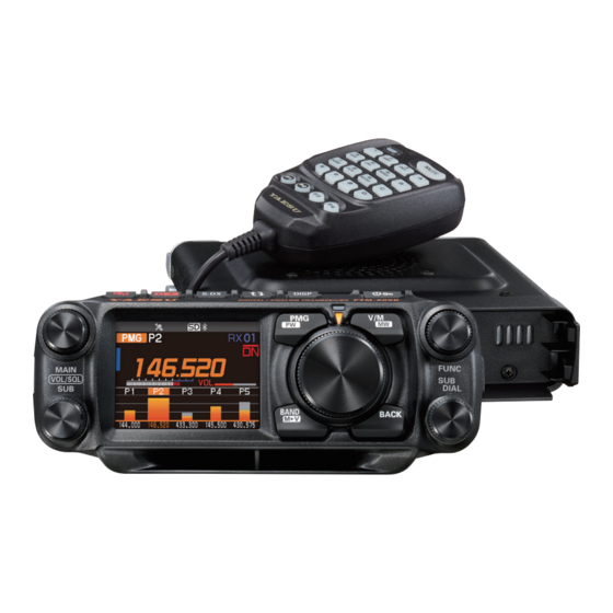
Yaesu FTM-500DR Operating Manual
C4fm/fm 144/430mhz dual band digital transceiver
Hide thumbs
Also See for FTM-500DR:
- Advance manual (74 pages) ,
- Operating manual (33 pages) ,
- Instruction manual (32 pages)

Related Manuals for Yaesu FTM-500DR


Summary of Contents for Yaesu FTM-500DR
- Page 1 C4FM/FM 144/430MHz DUAL BAND DIGITAL TRANSCEIVER FTM-500DR FTM-500DE Operating Manual...
-
Page 2: Table Of Contents
Restoring to Defaults (Reset) ...... 74 About the antenna ........33 Connection of Antenna and Power Cables .. 33 Text input screen .......... 75 Installing the Transceiver/Microphone ..34 Specifications ..........76 YAESU LIMITED WARRANTY ...... 78 Install the main body using the supplied bracket ..........34... -
Page 3: Introduction
Compatible with microSD memory cards Thank you for purchasing the FTM-500DR/DE Transceiver. We urge you to read this manual in its entirety, and also the Advance Manual (available for download on the Yaesu website), to gain a full understanding of the amazing capability of the exciting new FTM-500DR/DE Transceiver. -
Page 4: Quick Guide
Set the Bluetooth function ® : to delete character to left of cursor The FTM-500DR/DE is equipped with the See “Text input screen” on page 75 Bluetooth function. To use a Bluetooth to input a call sign. Operation” headset, refer to “Bluetooth ®... -
Page 5: Supplied Accessories And Options
Supplied Accessories and Options Supplied Accessories • DTMF microphone SSM-85D • DC power cable (with fuse attached) • Bracket for main body • Spare fuse (15A) • Operating Manual (This Manual) If any item is missing, contact the dealer from which you purchased the transceiver. Available Options • Swing Head Kit SJMK-500... -
Page 6: Basic Operation
Basic Operation Turning the Transceiver ON 1. Press and hold the POWER (LOCK) switch to turn the transceiver ON / OFF. Press and hold S-DX DISP FTM - 500D DIGITAL / ANALOG TRANSCEIVER z Inputting the call sign 1. The first time the transceiver is turned ON after it is pur- chased;... -
Page 7: Adjusting The Volume
Adjusting the volume 1. Rotate the VOL knob to adjust the volume to a comfortable level. S-DX DISP FTM - 500D DIGITAL / ANALOG TRANSCEIVER Adjust the volume for Main Band (upper) Adjust the volume for Sub Band (lower) Adjusting the squelch level Annoying noises can be muted when a signal cannot be detected. -
Page 8: Tuning To A Frequency
Tuning to a Frequency Press the key to select the desired frequency band. S-DX DISP FTM - 500D DIGITAL / ANALOG TRANSCEIVER Rotate the DIAL knob to select the desired frequency. AIR Band 108MHz - 137MHz ② 144MHz Band 137MHz - 174MHz ①... -
Page 9: Switch Between Main Band And Sub Band
z The numeric keys on microphone Press the numeric keys “0” to “9” to enter the frequency. Example: To input 145.520 MHz [1] [4] [5] [5] [2] Example: To input 430.000 MHz [4] [3] [Press and hold any numeric key] While entering a frequency using the numeric keys, the entry may be canceled by pressing PTT. -
Page 10: Useful Functions
Useful Functions CFL: Custom Function List ..........page 16 From 127 items of the Setup Menu, frequently used functions in the Function List can be registered and then recalled by simply pressing the FUNC knob. The Function List screen displays the registered functions and current settings in an easy-to-read form, so you can immediately select and use the function. -
Page 11: Pmg (Primary Memory Group)
PMG (Primary Memory Group) ..........page 14 The PMG function that displays the receive status of registered channels in a bar graph allows registration of up to 5 channels by pressing and holding the for the current display frequency of either the VFO or the memory channel. The PMG screen can be switched to auto mode or manual mode by press and hold the DIAL knob. -
Page 12: Band Scope
Band Scope ................page 12 The receive status (signal strength) of the channels before and after the current fre- quency can be displayed as a bar graph, whether in VFO mode or in memory mode. Press the key to display the band scope Press: Displays the band scope screen. -
Page 13: Setup Menu List
Setup Menu List Frequently used items from the below 127 Setup Menu types, can be registered to the Function List. (See page 16) The gray Setting items are registered in the Func- tion List by factory default. See page 66 for detail information on the Setup Menu. DISPLAY SIGNALING 85 BEACON TX SET... -
Page 14: Switch Between Dual Receive And Scope Operation With One Touch
Switch between Dual receive and Scope operation with one touch Dual receive and Scope operations are switched each time the key is pressed. The center frequency or memory channel can be changed by turning the DIAL knob. In VFO Mode, press and then turn the DIAL knob to select the frequency in 1MHz increments. -
Page 15: Search & Go (Short Press)
Search & Go (Short press) • Touch on the Scope screen, Bar graph to access SUB VFO dual receive. Scope Screen Scope Screen Change operation to, VFO mode Touch the bar or, Memory mode Dual Receive at the frequency touched on the Bar graph Dual Receive on the scope screen Touch to return to the previous screen... -
Page 16: Pmg (Primary Memory Group)
PMG (Primary Memory Group) PMG Function The PMG function allows the status of multiple channels to be displayed in real time on the Bar Graph, while listening to the Receive Channel. In manual mode, turn the DIAL knob to select the Receive Channel, and also observe the status of other channels on the Bar Graph. -
Page 17: Normal Mode (Manual Mode)
Normal Mode (Manual Mode) • Displays the current received signal in orange. • Displays historical received signal strengths in gray (Press the DIAL knob to reset). • Press the blinking area of the screen during Dual Receive, Dual Receive will be canceled and the original PMG function will be restored. -
Page 18: Cfl (Customized Function List)
CFL (Customized Function List) Easily operate frequently used functions by calling them from the function list with one- touch operation of the FUNC knob. You can view the list of registered priority functions and the setting status at a glance, and you can execute the function or change the set- ting just by selecting and pressing with the FUNC knob. -
Page 19: Registration To The Function List
Registration to the Function List 1. Press and hold the FUNC knob. DISPLAY The Setup Menu screen is displayed. FREQUENCY INPUT > 2. Rotate the FUNC knob to select the item to be regis- LCD BRIGHTNESS tered in the Function List. FREQUENCY COLOR BAND SCOPE 3. -
Page 20: Aess (Acoustic Enhanced Speaker System)
AESS (Acoustic Enhanced Speaker System) The phase adaptation speaker system AESS (Acoustic Enhancement Speaker System) is generated conjointly by the main-unit speaker and the front speaker. By varying the phase, output balance, and frequency characteristics of the front and main speaker out- put, AESS achieves clear, high-fidelity audio that reduces fatigue even when used for sustained communications. -
Page 21: Name And Function Of Each Component
Name and function of each component Control Head (front) S-DX DISP FTM - 500D DIGITAL / ANALOG TRANSCEIVER VOL/SQL knob Rotate the VOL/SQL Knob to adjust the audio vol- VFO mode ume level. • Press: VOL/SQL knob (Upper): Main-Band Each key press switches the operating frequency VOL/SQL knob (Lower): Sub-Band band. - Page 22 Mode indicator The current operating mode is indicated by the Press the this key to return to the previous screen. color of the LED. FUNC knob Blue mode • Press: Display the CFL (Customized Function List) Green When memory is recalled. screen.
-
Page 23: Control Head (Top)
Internet. (For details on this function, refer to the WIRES-X Function Instruction Manual which may be downloaded from the Yaesu website.) Press and hold the this key again to return to the normal operation screen. -
Page 24: Control Head (Left And Right Side)
Control Head (Left and right side) micro-SD card slot MIC jack Insert a commercially available micro SD card to Control Head angle adjusting Screw backup the various radio settings, memory chan- Loosen these screws to change the angle of the nels, recordings of received audio, and recordings control head. -
Page 25: Main Body
Main body (Front) CONTROL jack MIC jack Plug the control cable into this jack to connect with Connect the cable of the included DTMF micro- the control panel. phone SSM-85D or the optional microphone MH- 42C6J. Main body (rear) ANT terminal EXT SP A jack / EXT SP B jack Connect the co-axial cable for the antenna. -
Page 26: Microphone (Ssm-85D)
Microphone (SSM-85D) DTMF keypad Speak into the microphone during transmission. Press these keys during transmit to enter and send a DTMF sequence. The following operations can TX LED be performed during receive. Lights red while pressing PTT switch. 0 - 9 : Enter the frequency or memory channel number. - Page 27 Program keys (P1/P2/P3/P4) The default function settings of the [P1] / [P2] / [P3] / [P4] keys are shown in the table below. Function Press Press and hold 2nd PTT Transmit on the SUB Band frequency (at the bottom of the screen) HOME Recalls HOME channel Selects communication mode...
-
Page 28: Display
Lights when VOX function is activated Lights when the mute function is activated LOCK Displays mode Display of settings such as DG-ID/TONE Displays memory name (tag) YAESU MUSEN Communication Mode Mode/Status indicator Main-band frequency S-meter/transmit power level Volume/Squelch Bar Graph (Main-band) - Page 29 z Main-Band / Sub-Band display area Displays mode (VFO Mode and Memory Mode are switched each time the Mode area is touched.) Memory channels of the same frequency band are automatically grouped and re- called as follows by the memory auto grouping (MAG) function. M-ALL : Recalls all memory channels regardless of frequency band M-AIR : Recalls only memory channels in the AIR band (108 - 137MHz).
-
Page 30: Descriptions Of Main Screens
Communication Mode (The Operating Mode switches each time the Mode area is touched.) Displays the operating mode (Digital modes are indicated by a red icon) : FM (Analog) mode : AM (Analog) mode : V/D mode (Simultaneous voice and data communication mode) : Voice FR mode (Voice full-rate mode) : Data FR mode (High speed data communication mode) : AMS (Automatic Mode Select) FM (Analog) mode... - Page 31 z Band Scope screen Press the key to display the Band Scope screen. The strengths of received signals above and below the current frequency or memory channel are shown in a graph while sweeping at high speed. The audio of the center frequency is heard without interruption.
-
Page 32: About This Manual
z BACKTRACK screen Press and hold the FUNC knob → [7 DISPLAY MODE] → TRACK] • Real-time navigation function Displays the position and direction of the other station in real time during communication in C4FM digital V/D mode (The signal of the other station must contain GPS location information). It is also possible to switch the display to show the traveling direction of your own station and the distance to the destination. -
Page 33: Safety Precautions ( Be Sure To Read )
Be sure to read these important precautions, and use this product safely. Yaesu is not liable for any failures or problems caused by the use or misuse of this product by the purchas- er or any third party. Also, Yaesu is not liable for damages caused through the use of this product by the purchaser or any third party, except in cases where ordered to pay damages under the laws. - Page 34 Never cut off the fuse holder of the DC power cord. When transmitting, keep the antenna at least 1.8m This may cause short-circuiting and result in ignition (VHF) or 2.2m (UHF) away from your body.Do not and fire. use modified or damaged an-tennas. Do not use fuses other than those specified.
-
Page 35: Installing The Radio
Installing the Radio About the antenna The antenna is an extremely important part for both transmitting and receiving. The antenna type and its inherent characteristics determine whether the performance of the transceiver can be fully realized. As such, please note the following: ... -
Page 36: Installing The Transceiver/Microphone
Installing the Transceiver/Microphone The control head and main body are connected with a control cable. When needed, use the optional Control Cable 20ft (6m) to connect the main body to the “CONTROL” terminal of the control head. Connect the supplied microphone SSM-85D to the “MIC” terminal of the transceiver or control head. -
Page 37: Using The Optional Swing Head Kit "Sjmk-500
Using the optional Swing Head Kit “SJMK-500” The optional control head extension cable “CT-132” is not required. Freely change the angle of the control head up, down, left, or right. z Remove the control head from the transceiver body To install the SJMK-500 Swing Head Kit, remove the control head from the transceiver body. -
Page 38: Using A Micro Sd Memory Card
• A microSD memory card that was used in another device may not function properly, for example, it may not be recognized by the FTM-500DR/DE, or reading and writing may take an unusually long time. Use of the SD Memory Card Formatter provided by the SD Association may improve this. -
Page 39: Functions To Use As Needed
Functions to use as needed Selecting the Communication Mode z Using AMS (Automatic Mode Select) function Press The FTM-500DR/DE transceiver is equipped with the AMS S-DX DISP (Automatic Mode Select) function which automatically DIGITAL / ANALOG TRANSCEIVER selects the communication mode corresponding to the received signal. -
Page 40: Fixing The Communication Mode
Fixing the Communication Mode To fix the transmit operation Press mode, press the key or touch the mode icon to select S-DX DISP DIGITAL / ANALOG TRANSCEIVER FTM - 500D the communication mode. When the AMS function is OFF, the “bar” above the mode icon disappears. -
Page 41: Setting The Skip Band
Setting the Skip Band Set the band selected when the key is pressed. By storing frequently used fre- quencies in the memory channel before setting the band skip, can be recall the memory that stores the frequencies of the bands that cannot be selected. 1. -
Page 42: Using The Convenient Digital C4Fm Features
When accessing a C4FM digital repeater controlled by a DG-ID number, set the transmit DG-ID number of the FTM-500DR/DE to that of the repeater input. Even in that case, if the receive DG-ID number of the FTM-500DR/DE is set to “00”, all the downlink signals from the repeater may be received. - Page 43 • The other stations must also have the GM (Group Monitor) function ON. • Refer to the separate Operating Manual GM Edition for details on how to use the GM function (download the manual from our YAESU website). 7. Press the key to turn the GM (Group Monitor) function OFF and return to nor- mal operations.
- Page 44 24 stations with the GM function turned ON, and that are within the communi- cation range, may be checked. For details on how to set each item, refer to “FTM-500DR/DE GM Function Instruction Manual” which is available on the Yaesu website.
-
Page 45: Repeater Operation
If you need to access the repeaters which requires a 1750Hz burst tone for access by the FTM-500DR (USA/Asian versions), you can set the program key on the microphone to serve as a “T-CALL” key instead. To change the configuration of this... -
Page 46: Using The Memory
Using the Memory The FTM-500DR/DE incorporates a Large number of memory channels that can register the operating frequency, communication mode, and other operational information. • 999 Memory Channels • 5 Home Channels • 50 pairs PMS Memory Channels m The memory auto grouping (MAG) function can automatically recall a list of memory channels from the same frequency band as a group. -
Page 47: Recall Memory (There Are Two Ways)
3. Press and hold the key. MEMORY CH LIST Or press the FUNC knob to display a popup. Make sure 001 145.000 that [WRITE] is highlighted and press the FUNC knob. ー ー ー ー If you attempt to register a frequency to a memory channel that already contains frequency data, “OVER- ー... -
Page 48: Copy Memory Channel Information To Vfo
(3) Recalling a memory by directly entering the channel number z Recalling a memory on the keypad screen 1. Press the FUNC knob. HOME CH KEYPAD 2. Touch [KEYPAD]. SCAN TXPWR HIGH Or rotate the FUNC knob, select [KEYPAD], then AUTO press the FUNC knob to display the memory channel RPT-R... -
Page 49: Recall Only Memories In The Same Frequency Band (Band) Using The Memory Auto Grouping (Mag) Function
Displaying a list of memory channels in memory mode Turning the DIAL knob in memory mode usually increases or decreases the mem- ory channel number. Rotating the DIAL knob automatically displays the memory channel list and allows you to recall the desired memory channel while checking the contents of multiple memory channels. -
Page 50: Edit Memory
• Rotate the SUB DIAL knob, or press the [UP] or ー ー ー ー [DWN] key on the microphone to fast-forward in ー ー ー ー 10-channel steps. ー ー ー ー MEMORY CH LIST 021 433.300 YAESU 022 433.620 FTM-500D 433.300 JA1YOE 433.100 DIGITAL 433.200 3. - Page 51 Select [MEMORY CH LIST] Press the FUNC knob The last used memory channel is selected. MEMORY CH LIST 2. Rotate the FUNC knob to select the memory channel 021 433.300 YAESU from which the data is to be cleared, and press the FUNC knob. 022 433.620 FTM-500D • Rotate the SUB DIAL knob, or press the [UP] or...
-
Page 52: Recalling The Home Channels
Recalling the Home Channels z Recall from the Function List 1. Press the FUNC knob. HOME CH KEYPAD 2. Touch [HOME CH]. SCAN TXPWR HIGH Or rotate the FUNC knob, select [HOME CH], then AUTO press the FUNC knob. RPT-R TONE 100.0 • Or press and hold the FUNC knob → “19 HOME CH”... -
Page 53: Split Memory
3. Rotate the FUNC knob to select the channel number that the receive frequency was registered to on step1, and press the FUNC knob. 4. Touch [EDIT]. MEMORY CH LIST Or rotate the FUNC knob to select [EDIT], then press 021 433.300 YAESU the FUNC knob. 022 433.620 FTM-500D 433.300 JA1YOE 433.100... -
Page 54: Scanning Function
Scanning Function The FTM-500DR/DE supports the following three scanning functions: • VFO Scan • Memory Scan • Programmable Memory Scan (PMS) VFO Scan / Memory Scan To find frequencies where there are signals in VFO mode or Memory mode: 1. Press the... -
Page 55: Skip Memory Channels
PMS Programmable Memory channels. 50 sets of PMS memory channels (L01/U01 to L50/U50) are available. For additional details on the Programmable Memory Scan (PMS) and Memory Bank Scan, refer to the Advanced Manual which may be downloaded from the Yaesu website. -
Page 56: Convenience Features
Convenience Features ® Bluetooth Operation The FTM-500DR/DE has built-in Bluetooth functionality. Hands-free operation is pos- ® sible using the optional Bluetooth headset (SSM-BT10) or a commercially available ® Bluetooth headset. ® The operation of all commercially available Bluetooth headsets cannot be guaranteed. - Page 57 ® the power of the same Bluetooth headset is turned ON in this state, it will con- ® nect automatically. If not, turn the FTM-500DR/DE and Bluetooth headset OFF ® and then ON again. • To connect to other Bluetooth headsets, refer to “Connect with another...
-
Page 58: Vox Operation
(when the VOX function is OFF) When the VOX function is OFF, pressing the “Call button”* on the Bluetooth headset ® once will engage the FTM-500DR/DE in transmit, and then a call can be made using the Bluetooth headset. ®... - Page 59 Set the VOX (Voice Operated Transmit) delay time During transmissions using the VOX (Voice Operated Transmit) function, set the time to return to receive when speaking is paused: 1. Press and hold the FUNC knob. S-DX DISP DIGITAL / ANALOG TRANSCEIVER FTM - 500D 2.
- Page 60 DEVICE LIST (2) Searched and found new SSM-BT10 Bluetooth devices: white letters ® (3) Already registered but not found by search yaesu-01 Bluetooth devices: gray letters ® yaesu-02 6. When the headset to be connected is displayed, press R556 key to stop searching.
- Page 61 ® Bluetooth received audio output ® When a Bluetooth headset is connected, the received audio can automatically be output from the headset only, or from both the headset and the transceiver speaker. 1. Press and hold the FUNC knob. S-DX DISP DIGITAL / ANALOG TRANSCEIVER FTM - 500D...
-
Page 62: Dual Receive Function
Dual Receive Function While receiving on the VFO or Memory Chanel, the transceiver checks for signals on the HOME channel once every 5 seconds. When a signal is received on the HOME channel, the priority scan pauses, allowing reception of the signal. When there is no signal on the HOME channel for about 5 seconds, the transceiver will resume Priority Scan. -
Page 63: Using The Voice Recorder
MicroSD memory card. The recorded file can be played back with the FTM-500DR/DE or the MicroSD memory card can be taken out and used on a PC. Once recording is started, it continues until recording is stopped, or the capacity of the MicroSD card is full. - Page 64 Setting the Recording function The band or bands to be recorded, and whether or not to include the transmit audio in the recording may be selected: 1. Press and hold the FUNC knob. S-DX DISP DIGITAL / ANALOG TRANSCEIVER FTM - 500D 2.
- Page 65 Playback the recorded audio Playback is not possible during recording, so stop recording and follow the steps below to play back. 1. Press and hold the FUNC knob. S-DX DISP DIGITAL / ANALOG TRANSCEIVER FTM - 500D 2. Touch [63 LOG LIST]. Or rotate the FUNC knob to select [63 LOG LIST], then press the FUNC knob.
-
Page 66: Gps Function
LCD of your transceiver. Setting several station parameters, such as the call sign and symbol is required before using the APRS function (initial settings). For details, refer to the APRS Function Instruction Manual which is available on the Yaesu website. -
Page 67: Tone Squelch Feature
For additional details on the following Functions, refer to the Advanced Manual which may be downloaded from the Yaesu website. Tone squelch feature The tone squelch opens the speaker audio only when a signal containing the specified CTCSS tone is received. By matching the CTCSS tone frequency with the partner sta- tions, quiet standby monitoring is possible. -
Page 68: Using Setup Menu
Using Setup Menu The Set Mode permits configuring the various functions to accommodate individual op- erating needs and preferences. Setup Menu Operation 1. Press and hold the FUNC knob. S-DX DISP FTM - 500D DIGITAL / ANALOG TRANSCEIVER The SETUP MENU screen will be displayed. 2. -
Page 69: Tables Of Setup Menu Operations
Tables of Setup Menu Operations Selectable options Menu Number / Item Description (Options in bold are the default settings) DISPLAY 1 FREQUENCY INPUT Enter frequency directly or display memory channel list. 2 LCD BRIGHTNESS Display and key button brightness. MIN / MID / MAX 3 FREQUENCY COLOR Set the font color of the operation WHITE / BLUE / RED... - Page 70 Selectable options Menu Number / Item Description (Options in bold are the default settings) 21 MEMORY LIST MODE Displays a list of memory channels in ON / OFF memory mode. 22 PMG PMG TIMER Scan resume time after there is no 1sec / 2sec / 3sec signal when receiving in PMG mode simultaneously.
- Page 71 Selectable options Menu Number / Item Description (Options in bold are the default settings) 42 FRONT SP MUTE Front speaker operation settings when CONTINUE / AUTO MUTE external speakers are connected. SIGNALING 43 DTMF Load DTMF Autodialer Memories. – 44 DTMF MEMORY Set the DTMF auto dialer channel and 1 to 9 code (16 characters).
- Page 72 NMEA 7 /NMEA 8 / NMEA 9 WP FILTER: ALL / MOBILE / FREQUENCY / OBJECT/ITEM / DIGIPEATER / VoIP / WEATHER /YAESU / CALL RINGER / RANGE RINGER 70 DATA BAND APRS/DATA band selection settings. APRS: MAIN BAND / SUB BAND /...
- Page 73 Selectable options Menu Number / Item Description (Options in bold are the default settings) 77 APRS MUTE OFF / ON Set audio mute for APRS band. 78 APRS POPUP Beacons and messages Pop-up BEACON: OFF / 3sec / 5sec / 10sec / display time setting.
- Page 74 Sort function / Filter function settings. SORT: TIME / CALLSIGN / DISTANCE FILTER: ALL / MOBILE / FREQUENCY / OBJECT/ITEM / DIGIPEATER / VoIP / WEATHER / YAESU / OTHER PACKET / CALL RINGER / RANGE RINGER / 1200 bps / 9600 bps...
- Page 75 Selectable options Menu Number / Item Description (Options in bold are the default settings) READ FROM SD Loads the information to the transceiver from a microSD memory card. Copies all data. MEMORY Copies only the memory channels and backtrack position information. SETUP Copies only the set-up menu settings.
-
Page 76: Restoring To Defaults (Reset)
Restoring to Defaults (Reset) Caution When the All Reset function is performed, all data registered in the memory will be deleted. Be sure to note the settings on paper or back up the data on a microSD memory card. All Reset To restore all transceiver settings and memory content to the factory defaults. -
Page 77: Text Input Screen
Text input screen The keyboard screen is displayed when entering your own station call sign or memory channel tag. z Character input method 1. Touch a character on the screen to enter it. Or rotate the FUNC knob to select a character, then press the FUNC knob. -
Page 78: Specifications
Specifications z General Frequency Range : TX 144 - 148MHz or 144 - 146MHz 430 - 450MHz or 430 - 440MHz (Depends on the transceiver version) : RX 108 - 137MHz (AIR Band) 137 - 174MHz (144MHz HAM / VHF Band) 174 - 400MHz 400 - 480MHz (430MHz HAM / UHF Band) 480 - 999.995MHz (USA Cellular Blocked) - Page 79 The Bluetooth wordmark and logo are registered trademarks owned by Bluetooth SIG, Inc. and are ® used under license by Yaesu Musen Co., Ltd. About internal spurious signals Certain frequency combinations of signals received simultaneously, may cause some effect on the receiver mixer and IF circuits due to the high frequency of the internal oscillator.
-
Page 80: Yaesu Limited Warranty
Limited Warranty is valid only in the country/region where this product was originally purchased. On-line Warranty Registration: Thank you for buying YAESU products! We are confident your new radio will serve your needs for many years! Please register your product at www.yaesu.com - Owner’s Corner... - Page 81 YAESU dealer/distributor from whom the product was originally purchased. 2. Include proof of original purchase from an authorized YAESU dealer/distributor, and ship the product, freight prepaid, to the address provided by the YAESU Service Center in your country/ region.
- Page 82 Changes or modifications to this device that are not expressly approved by YAESU MUSEN could void the user’s authorization to operate this device. This device complies with part 15 of the FCC Rules. Operation is subject to the following two conditions: ( 1 ) This device may not cause harmful interference, and ( 2 ) this device must accept any interference including received, interference that may cause undesired operation.
- Page 83 UKCA Declaration of Conformity We, Yaesu Musen Co. Ltd of Tokyo, Japan declare our sole responsibility that this equipment com- plies with essential requirements of the Radio Equipment Regulations 2017, Electrical Equipment...
- Page 84 Copyright 2023 YAESU MUSEN CO., LTD. All rights reserved. No portion of this manual may be reproduced without the permission of YAESU MUSEN CO., LTD. YAESU MUSEN CO., LTD. Omori Bellport Building D-3F 6-26-3 Minami-Oi, Shinagawa-ku, Tokyo, 140-0013, Japan YAESU USA...
Need help?
Do you have a question about the FTM-500DR and is the answer not in the manual?
Questions and answers