Table of Contents
Advertisement
Quick Links
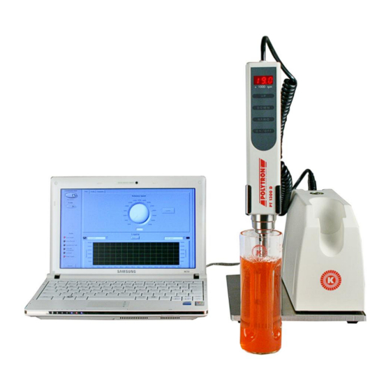
Instruction Manual for
POLYTRON
This is a quality product of:
Luzernerstrasse 147a
CH-6014 Lucerne Fax: +41-41-259 65 75
Switzerland
®
System PT 1300 D
Voltage
90 – 260 V, 50/60 Hz
Make sure the power supply is correct and corresponds with the
technical data plate on the instrument
Tel.: +41-41-259 65 65
E-mail:laboratory@kinematica.ch
Advertisement
Table of Contents

Subscribe to Our Youtube Channel
Related Manuals for Kinematica POLYTRON PT 1300 D


Summary of Contents for Kinematica POLYTRON PT 1300 D
- Page 1 90 – 260 V, 50/60 Hz Make sure the power supply is correct and corresponds with the technical data plate on the instrument This is a quality product of: Luzernerstrasse 147a Tel.: +41-41-259 65 65 CH-6014 Lucerne Fax: +41-41-259 65 75 Switzerland E-mail:laboratory@kinematica.ch...
-
Page 2: Table Of Contents
INDEX: PAGE: INTRODUCTION ............................3 OPERATING INSTRUCTIONS ........................ 3 ORGANISATIONAL MATTERS ......................5 WARNING NOTICES ..........................6 SAFETY ..............................6 SUMMARY ............................... 7 SAFETY CONCEPT ..........................7 RESIDUAL DANGERS .......................... 10 WARNINGS............................11 USE ................................13 ............................13 ESCRIPTION POLYTRON ........................ -
Page 3: Introduction
THE OBLIGATION TO INSPECT YOUR EQUIPMENT CAREFULLY AND TO CLEAN IT THOROUGHLY. KINEMATICA AG is a specialist manufacturer of machines and equipment for dispersion and mixing technology. An important objective of these operating instructions is to fully inform you, the user, about the correct and safe use of our equipment. - Page 4 1.1.1 RANGE OF VALIDITY The information in these operating instructions relates to the POLYTRON ® identified as follows: KINEMATICA AG, CH-6014 Luzern Manufacturer: POLYTRON ® Brand name: ® ® POLYTRON PT 1300 D & POLYTRON PT 1300 D RS232 Product name:...
-
Page 5: Organisational Matters
The operating instructions can only be of use to you if you always have them at hand. They should therefore always be kept at the place where the equipment is used. 1.2.2 MANUFACTURER CONTACT ADDRESS KINEMATICA AG Luzernerstrasse 147a CH-6014 Lucerne... -
Page 6: Warning Notices
DEVICE NOT DESIGNED FOR USE IN EXPLOSION DANGER ENVIRONMENT. 2 SAFETY This chapter is directed at all users of KINEMATICA laboratory equipment. It includes information on safe and optimum use. OI PT 1300 D English / Edition 3.0 / 23.10.2009... -
Page 7: Summary
2.1 SUMMARY Any incorrect use of the installed equipment can be dangerous. Inadequately trained users can cause material damage and personal injury. This chapter informs you about the safety concept and the requirements for safe and optimum use of the equipment. All those authorised to operate, service and repair the equipment are required to study chapter 2, “Safety”. - Page 8 Contract partner: The manufacturer can impose legal obligations on the contract partner when the equipment is purchased. The contract partner is obliged to ensure that the equipment is properly used. Operating company: The operating company ensures that the equipment is properly used and authorises persons who are entitled to work with the equipment in any one of the defined user roles.
- Page 9 2.2.4 DANGER AREA System/equipment The system danger area includes the whole system/equipment including the connecting lead and controls. Proximity danger area This refers to all areas within a defined distance of the equipment. User danger area This danger area includes all persons working with the equipment. 2.2.5 AREAS OF RESPONSIBILITY In order that the system/equipment can be used safely and without risk, the users in various roles bear the responsibility for particular danger areas.
-
Page 10: Residual Dangers
2.2.6 GENERAL SAFETY RULES Observe the following general safety rules: follow these operating instructions, in addition, observe the legal obligations and requirements for accident prevention and environmental protection of the country in which you operate the equipment, do not make any modifications to the equipment without the written authorisation of the manufacturer, ... -
Page 11: Warnings
2.4 WARNINGS Ensure that the rated voltage of the equipment matches the supply. Before changing any dispersing aggregate, the line cord has to be plugged out IT IS IMPORTANT THAT THE MAINS SUPPLY WHERE THE DEVICE IS PLUGGED IN COMPLIES WITH THE INFORMATION ON THE TYPE LABEL AND THE INTERNATIONAL STANDARDS FOR POWER SUPPLIES. - Page 12 When the line cord is plugged, never touch the saw teeth of the aggregate – danger of injuries due to rotating shafts and blades KINEMATICA AG products comply with all the usual CE directives, carry the CE marking and are delivered with a corresponding declaration of conformity.
-
Page 13: Use
PT 1300 D handheld units are specially designed for the dispersing, POLYTRON homogenizing, suspending, emulsifying, decomposing and mixing of organic and inorganic sample material in small quantities. 3.1 DESCRIPTION PT 1300 D consists of a microprocessor-controlled supply and control POLYTRON module and a high-performance low-voltage drive with a control and operating module including an LED display as well as a selection of three different homogenizing... - Page 14 Dispersing units (choice) PT-DA PT-DA PT-DA PT-DA PT-DA 07/2EC-E107 12/2EC-E123 12/2EC-E157 12/2MEC-E157 12/2WEC-E157 Shaft length, mm Stator/Rotor Ø, 7.8/5 12/9 12/9 12/9 12/9 Processing 0.5 – 10 ml 3 – 250 ml 3 – 250 ml 3 – 250 ml 3 –...
-
Page 15: Option Stand St-P00/200
3.4 STAND ST-P12/600 P T 1300 D handheld units can be used with the optinal plate stand ST- POLYTRON P00/200. The stand consists of the following components: Baseplate Stand column with a maximum stroke of about 550mmMotor mounting with ... -
Page 16: Technical Specifications
Make sure that the mounting screw on the rear side of the stand has been tightened firmly so that the stand arm cannot move away during operation. (see the installation drawing enclosed) 3.6 TECHNICAL SPECIFICATIONS POLYTRON PT 1300 D motor type Brushless DC-motor, electronically commuted supply voltage... -
Page 17: Installation
ABOUT ANY DISAGREEMENT OR FAULT. IF POSSIBLE SEND DIGITAL PHOTOS EMAIL LABORATORY@KINEMATICA.CH 4.2 COUPLING/DECOUPLING OF THE HOMOGENIZING AGGREGATE PT 1300 D handheld units are equipped with quick-coupling. POLYTRON Dispersing aggregates with diameters of 3, 5, 7 and 12 mm are available for the PT 1300 D drive unit. -
Page 18: Working With The Pt 1300 D
To remove the aggregate from the drive, push the retaining ring of the coupling upward and/or in the direction of the drive. At the same time, the aggregate is to be carefully pulled downward in the axial direction so that the homogenizing aggregate is not tilted in the coupling housing (see the enclosed assembly sketch). - Page 19 THE MAXIMUM SUBMERSION DEPTH IS BENEATH THE UPPER SCAVENGING HOLE OF THE STATOR TUBE. Switch on the control and operating module by using the ON/OFF switch. The unit now runs at the lowest rotational speed of 2000 rpm. Once the ON / OFF button is pressed the fan runs.
- Page 20 4.4 FUNCTIONAL DESCRIPTION OF THE KEY With the ON/OFF switch, turn on the control and operating module as ON/OFF soon as the main switch has been turned on at the supply and control module. The rotational speed will be 2’000 rpm if the PT 1300 D has meanwhile been switched off by means of the main switch, otherwise the control and operating module uses the last set rotational speed.
- Page 21 To acknowledge the fault, you have to set OFF the main switch. The unit must be restarted after that. If the fault can not be resetted the unit must be sended to KINEMATICA AG for repair. 4.5.5 INTERFACE The hardware from the PT 1300 D is equipped by default with two Interfaces.
-
Page 22: Maintenace
The supply and control module does not require any special maintenance. There are also no parts that need or can be serviced or replaced by the operator. In the case of a malfunction, please contact KINEMATICA AG or your supplier. 5.2 MAINTENACE OF THE CONTROL AND OPERATING MODULE The control and operating module also does not require any special maintenance. -
Page 23: Disassembly Instructions
5.4 DISASSEMBLY INSTRUCTIONS PT-DA 03/2EC- PT-DA PT-DA PT-DA 12/2EC-E123 – 157 E050 05/2EC- 07/2EC- E068 – 085 E82 – 107 With the universal tool supplied, carefully knock With this attachment you receive an the rotor and attached shaft out in the direction additional tool. -
Page 24: Trouble Shooting
If the motor is defective contact authorised KINEMATICA service centre or directly to KINEMATICA AG Error message “SUP” The internal Voltage is outer range. Contact authorised KINEMATICA service centre or directly to KINEMATICA AG Vibrations Bent shaft Replace shaft Worn bearing(s) Replace bearing(s) -
Page 25: General Accessories
12 months with regard to material and production flaws. KINEMATICA AG hereby ensures repair of the unit free of charge and/or replacement of the sent-in defective parts free of charge, if an extensive inspection results in that this dealt with a production or material flaw. -
Page 26: Appendix
9 GUARANTEE The symbol of the crossed refuse container signifies that the product in the European Union to must be supplied to separate collection. Labeled products must not be disposed with household waste, rather must be left at a collection point for recycling electrical and electronic equipment. Recycling helps to reduce the consumption of raw materials and to protect the environment. - Page 27 OI PT 1300 D English / Edition 3.0 / 23.10.2009 Page 27 of 37...
- Page 28 OI PT 1300 D English / Edition 3.0 / 23.10.2009 Page 28 of 37...
- Page 29 OI PT 1300 D English / Edition 3.0 / 23.10.2009 Page 29 of 37...
- Page 30 OI PT 1300 D English / Edition 3.0 / 23.10.2009 Page 30 of 37...
-
Page 31: Appendix: Control With Rs-232-Interface
10.2 LEGEND FOR THE STAND ST-P01/200 1. Base plate 2. Mounting screw 3. swivel arm 4. arm 5. Handheld holder 6. Base Station centering 7. Arm Fixation 8. Arm Fixation OI PT 1300 D English / Edition 3.0 / 23.10.2009 Page 31 of 37... - Page 32 10.3 LEGEND FOR THE STAND ST-P12/600 1. Base plate 2. Column 3. Cross sleeve completely 4. Handheld 5. Drive holder complete 6. - 7. - 8. adjustment ring (as an Option) 9. Vessel holder complete (as an Option) 10. Cross sleeve completely (as an Option) OI PT 1300 D English / Edition 3.0 / 23.10.2009 Page 32 of 37...
- Page 33 10.4 LEGEND FOR THE STAND ST-P15/320 1. Stand plate 2. Fixation screw 3. Drive holder 4. Base Station centering OI PT 1300 D English / Edition 3.0 / 23.10.2009 Page 33 of 37...
-
Page 34: Implementation
11 APPENDIX This chapter regards only units wit MODBUS Protocol respectively unitsw with following item number Item number Description 11010030 PT 1300 D MODBUS (with CH-Connector) 11010031 PT 1300 D MODBUS (with EU- Connector) 11010039 PT 1300 D MODBUS (with UK- Connector) 11.1 IMPLEMENTATION 11.1.1 SLAVE-ADDRESS The PT1300D has the fix address 0x01. - Page 35 11.2 REGISTER MAPPING The following mapping is integrated. Register Registeraddress R/W Remarks StartCmd Only value 1 allowed, Motor on SetSpeed Set rotation speed, range 10..300 [100rpm] StopCmd Only value 0 allowed, Motor off ActSpeed Actual speed, range 10..300 [100rpm] ActTemp Internal temperature [0.1°C] ActCrt Motor current [mA], average...
- Page 36 11.4 MODBUS EXCEPTIONS Illegal Function, only 0x03 and 0x06 are legal functions, all other are illegal Illegal Data Address, command 0x03 and Register-Address higher 15, command 0x06 and writing of a Register-Address higher 2 Illegal Data Value – does not exist on the PT1300D Remark: if more than 8 Byte recieved, is this a invalid communication.
- Page 37 11.6 PRECAUTIONS NEVER RUNNING THE PT 1300 D UNATTENDED. IF THE CONNECTION TO THE PC IS INTERRUPTED THE UNIT CONTINUES TO WORK. THE PLUG OF HANDHELD MAY NEVER BE STUCK OR BE INSERTED UNDER TENSION. BEFORE PLUGGING OR UNPLUGGING THE HANDHELD, ALWAYS SWITCH OFF THE MAIN SWITCH.
Need help?
Do you have a question about the POLYTRON PT 1300 D and is the answer not in the manual?
Questions and answers
Showing d EC in display and not working