Table of Contents
Advertisement
Quick Links
System POLYMIX
This is a quality product made by
Luzernerstrasse 147a
CH-6014 Littau-Luzern
Schweiz
QAQC LAB 589 Rappahannock Drive White Stone Va 22578 TEL (866) 244-1578 www.qclabequipment.com
Operating Instructions
Please check that the voltage is correct and corresponds with the
nameplate on the back of the machine.
Tel.:
Fax:
e-mail:
®
PX-MFC 90 D
Voltage
100...120 V, 50/60 Hz
210...250 V, 50/60 Hz
+41-41-259 65 65
+41-41-259 65 75
laboratory@kinematica.ch
Advertisement
Table of Contents

Related Manuals for Kinematica POLYMIX PX-MFC 90 D


Summary of Contents for Kinematica POLYMIX PX-MFC 90 D
- Page 1 This is a quality product made by Luzernerstrasse 147a Tel.: +41-41-259 65 65 CH-6014 Littau-Luzern Fax: +41-41-259 65 75 Schweiz e-mail: laboratory@kinematica.ch QAQC LAB 589 Rappahannock Drive White Stone Va 22578 TEL (866) 244-1578 www.qclabequipment.com...
-
Page 2: Table Of Contents
CONTENT: INTRODUCTION............................3 OPERATING INSTRUCTIONS ......................3 ORGANISATIONAL MATTERS ....................... 5 WARNING NOTICES ........................6 SAFETY ..............................7 SUMMARY ............................7 SAFETY CONCEPT......................... 7 RESIDUAL DANGERS........................10 WARNINGS............................ 11 DESCRIPTION OF THE MACHINE ....................... 13 OVERVIEW ............................ 13 DRIVE UNIT ........................... 16 GRINDING ATTACHMENTS ...................... -
Page 3: Introduction
KINEMATICA AG is a specialist manufacturer of machines and equipment for dispersion and mixing technology. - Page 4 1.1.1 RANGE OF VALIDITY ® The information in these operating instructions relates to the POLYMIX identified as follows: Manufacturer: KINEMATICA AG, CH-6014 Littau / Luzern ® Brand name: POLYMIX ® Product name: POLYMIX PX-MFC 90 D Artikelnummer Bezeichnung Drive POLYMIX® PX-MFC 90 D, 115 V, with US- power cable,...
-
Page 5: Organisational Matters
The operating instructions can only be of use to you if you always have them to hand. They should, therefore, always be kept at the place where the equipment is used. 1.2.2 MANUFACTURER AND CONTACT ADDRESS KINEMATICA AG Luzernerstrasse 147a CH-6014 Littau / Lucerne... -
Page 6: Warning Notices
1.3 WARNING NOTICES Please be aware of the meaning of the following warning signs: ATTENTION DANGER / WARNING! OBSERVE OPERATING INSTRUCTIONS. ATTENTION! DANGER OF ELECTRIC SHOCK. ATTENTION! WARNING OF HOT SURFACE. ATTENTION! MACHINE NOT SUITED FOR USE IN EX-AREAS Manual PX-MFC 90 D english / Release 2.0 / 29.12.2006 page 6 of 36 QAQC LAB 589 Rappahannock Drive White Stone Va 22578 TEL (866) 244-1578 www.qclabequipment.com... -
Page 7: Safety
2 SAFETY This chapter is directed at all users of KINEMATICA laboratory equipment. It includes information on safe and optimum use. 2.1 SUMMARY Any incorrect use of the installed equipment can be dangerous. Inadequately trained users can cause material damage and personal injury. This chapter informs you of the safety concept and the requirements for safe and optimum use of the equipment. - Page 8 2.2.3 USER ROLES To guarantee safety, we place requirements on the users of the equipment that must be met without fail. Only persons meeting the requirements are authorised to work with the equipment. We describe all those who work with the equipment as users. Since the requirements of these users are very much dependent on their activity, we distinguish the following user roles.
- Page 9 2.2.4 DANGER AREA System/equipment The system danger area includes the whole system/equipment including the connecting lead and controls. Proximity danger area This refers to all areas within a defined distance of the equipment. User danger area This danger area includes all persons working with the equipment. 2.2.5 AREAS OF RESPONSIBILITY In order that the system/equipment can be used safely and without risk, the users in various roles bear the responsibility for particular danger areas.
-
Page 10: Residual Dangers
Service technician: The service technician bears the responsibility for the “system/equipment danger area”. He ensures that the system/equipment is at all times free from technical faults, safe and functions correctly. 2.2.6 GENERAL SAFETY RULES Observe the following general safety rules: follow these operating instructions, in addition, observe the legal obligations and requirements for accident prevention and environmental protection of the country in which you operate the equipment,... -
Page 11: Warnings
AN EXPERT ELECTRICIAN MUST CARRY OUT ALL ELECTRICAL INSTALLATIONS 2.4 WARNINGS Make sure that the voltage of electric power source corresponds with • machine. Exchange grinding geometries only after electric power supply has been • disconnected.. The electric power supply system, to which the machine is connected, •... - Page 12 WARNINGS: continuation Only service specialists authorised by KINEMATICA AG may open the • machine. The areas around the ventilation grille and the ventilation slots at the • back of the machine must always remain unobstructed in order to ensure efficient cooling. If cooling is not sufficient, performance will decrease.
-
Page 13: Description Of The Machine
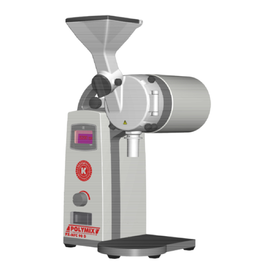
3 DESCRIPTION OF THE MACHINE The PX-MFC 90 D complies with all established and relevant CE-regulations, it carries the CE-label and is delivered with a corresponding declaration of conformity. 3.1 OVERVIEW ® The POLYMIX PX-MFC 90 D is a lab mill, suited for grinding batches of dry substances. By exchanging the grinding geometries the mill can be converted into a hammer mill or a cutting mill. - Page 14 Grab handle for relocation Display for rotation speed indicator and alarms Turning knob for speed Main switch adjustment Fig. 1 Cooling air intake Cooling air outlet Connector plug for power cable Rubber foot (5x) Fig. 2 Manual PX-MFC 90 D english / Release 2.0 / 29.12.2006 page 14 of 36 QAQC LAB 589 Rappahannock Drive White Stone Va 22578 TEL (866) 244-1578 www.qclabequipment.com...
- Page 15 Hopper lid Hopper for feeding product Metering Knurled screw for fixing/ loosening the metering Knurled screw Knurled screw for opening/ for fixing/ losing the loosening the chamber Stators (6x) Flange for NS29/32 – vessels Product outlet Manual PX-MFC 90 D english / Release 2.0 / 29.12.2006 page 15 of 36 QAQC LAB 589 Rappahannock Drive White Stone Va 22578 TEL (866) 244-1578 www.qclabequipment.com...
-
Page 16: Drive Unit
3.2 DRIVE UNIT The drive unit PX-MFC 90 D is equipped with a strong 1000 W motor and is switched on via the main switch on the front side of the machine. The machine disposes of an integrated electronic control system. Rotating speeds between 0 – 6000 rpm can be set. Maximum power is reached between 4500 and 5000 rpm. -
Page 17: Tools And Accessories
ATTENTION! DURING DETACHING, EXCHANGING OF UNITS THE DRIVE MUST BE DISCONNECTED FROM POWER SUPPLY. DURING LONGER OPERATION AND HIGH LOAD BOTH THE COUPLING AND THE DISPERSION UNIT CAN HEAT UP SIGNIFICANTLY - RISK OF BURNS. 3.4 TOOLS AND ACCESSORIES The mill is shipped with complete set of tools for dismounting, maintaining and cleaning. For dismantling of the blade-grinding rotor a special extractor tool is provided. -
Page 18: Technical Specifications
Tool for blade-grinding attachment dimension Identifier Item-no. Purpose Picture [mm] Dismantling Inboard- of the blade 9754548 146 x Ø50 extractor grinding rotor Provided accessories dimension Identifier Item-no. Purpose Picture [mm] Rack with Support for drawer for 12 9609114 245 x 135 x 84 tubes tubes &... -
Page 19: Installation
4 INSTALLATION 4.1 UNPACK Open the transport box and check whether contents are consistent with bill of delivery. CHECK ALL PARTS FO R POSSIBLE TRANSPORT DAMAGES. IMMEDIATELY REPORT INCONSISTENCY ERROR DIRECTLY TO US OR YOUR SPECIALIST DEALER. 4.2 START UP The drive unit is delivered ready-to-use with mounted grinding geometry. - Page 20 ASSURE THAT THE SIEVE IS PLACED INTO GROVE OF THE STATOR CORRECTLY AND NOT JUST PLACED ON THE STATOR. SEE IMAGE BELOW. WRONG ! • Check voltage on the basis of nameplate • Plug in power cable • Switch on main switch •...
-
Page 21: Exchange Of Grinding Attachments
4.3 EXCHANGE OF GRINDING ATTACHMENTS Dismounting/Mounting of the hammer-grinding attachment Make sure that the mill is switched off and the power cable disconnected before you start dismounting/mounting. First, pull out a possibly inserted sieve. Lock the hammer- rotor from below with the supplied rotating pin (1). - Page 22 Dismounting/Mounting of the blade-grinding attachment Make sure that the mill is switched off and the power cable disconnected before you start dismounting/mounting First, pull out a possibly inserted sieve. Lock the rotor from below with the supplied rotating pin (1). With the mandrel (3) inserted into the socket wrench (2), loosen the screw.
- Page 23 Place the extractor (1) in the groove. Afterwards rotating knob (2) so that the lips of the extractor grab the rotor. Fig. 9 When the rotor is grabbed, pull out the extractor with rotor, as shown in Fig. 10 and 11. Fig.
- Page 24 Both blade- and hammer- grinding stator should be removed using extractor hook. Place the extractor hook (1) in the inside threads, as shown in Fig. 12 & 13 Fig. 12 Fig. 13 When both hooks are inside the threads, pull out the stator using both hands, as shown in Fig.
-
Page 25: Maintenance
ATTENTION! DURING DETACHING, EXCHANGING OF GRINDING GEOMETRIES THE DRIVE MUST DISCONNECTED FROM POWER SUPPLY. DURING LONGER OPERATION AND HIGH LOAD THE GRINDING CHAMBER CAN HEAT UP SIGNIFICANTLY - RISK OF BURNS. MAKE SURE THAT GRINDING GEOMETRY GETS CLEANED THOROUGHLY AFTER EACH USAGE. NEVER TOUCH A ROTATING ROTOR OF THE GRINDING GEOMETRY. -
Page 26: Drive System
We strongly recommend to let service or repairs of the drive unit be performed only at authorised KINEMATICA service locations or directly at KINEMATICA, where original spare parts are available. Any changes that are not authorised or any manipulation will result in immediate cancellation of the warranty. - Page 27 Dismounting/Mounting of the hammer-grinding rotor Push out the pins (2) of the center (1) Mounting in reverse order Fig. 15 5.2.2 Blade-grinding attachment Stator: Dirty grooves can be cleaned with supplied scratch- out tool • and a needle. The 6-edge- depressions of the screws can also be cleaned •...
- Page 28 5.2.3 Grinding chamber The grinding chamber can be dismounted for cleaning purposes. Mounting/dismounting is described below: First remove the grinding rotor as described under 4.3. Loosen the 3 screws (1). The chamber can be removed. Subsequently the insert plate (2) and the felt seal (3) can be removed.
- Page 29 5.2.4 Gate with hopper The gate with integrated hopper can be dismounted for cleaning purposes. Mounting/dismounting is described below: Dis/mounting of the rotary slide Dismantle the screw (1) using the supplied hex wrench and pull out the rotary slide (2). Remove the O-ring (3).
-
Page 30: Spare Parts List
5.3 SPARE PARTS LIST The spare parts list is separated according to the assemblies: drive, hammer-grinding attachment and blade-grinding attachment. For ordering spare parts please advise assembly, identifier and article-no. Assembly Identifier Article-no. Position Figure no. rear guard plate 9753847 guard plate for gate 9753849 felt sealing... -
Page 31: Trouble Shooting
6 TROUBLE SHOOTING AUSE EMEDY ROBLEM Bearing drive motor Change ball bearings, find and unusual noise damaged replace defective parts Heating up Insufficient cooling Check ventilation slots Damaged bearing Change ball bearings Overload Check application Vibrations Twisted shaft Replace shaft Worn bearings Replace bearings. -
Page 32: Accessories
7 ACCESSORIES Stodger Order-No. Dimensions Material used for the active 35080001 300 x 26 x 23 POM black feeding of stringy materials hopper, which cannot be fed by its own weight. Sieves Order-No. Diameter-Ø Material Insert sieves can be 9609088 0.2 mm ordered with hole 9609089... -
Page 33: Warranty
8 WARRANTY KINEMATICA AG guarantees the flawless function of this machine manufactured by it for a period of 12 months with reference to material and manufacturing defects. KINEMATICA AG assures free repair of the machine or free replacement of delivered... -
Page 34: Appendix A. Dimensional Drawings
Appendix A. Dimensional drawings Drive PX-MFC 90 D Manual PX-MFC 90 D english / Release 2.0 / 29.12.2006 page 34 of 36 QAQC LAB 589 Rappahannock Drive White Stone Va 22578 TEL (866) 244-1578 www.qclabequipment.com... -
Page 35: Appendix B. Parts Lists
Appendix B. Parts lists Assembly Main Identification Order-No. Production-No. Products Identification Drive 230V with hammer- 9158043 grinding attachment ® POLYMIX PX-MFC 90 D 9835419 Power cable CH 35010020 230V / CH / H 9609114 Wooden rack 9851003 Tubes 9754504 Tools Drive 230V with hammer- 9158043 grinding attachment... - Page 36 Parts lists continued Assembly Main Identification Order-No. Production-No. Products Identification Drive 230V with blade- 9158067 grinding attachment 9835419 Power cable CH 9609114 Wooden rack ® POLYMIX PX-MFC 90 D 230V / 35010030 9851003 Tubes CH / B 9754504 Tools 9754548 Inboard extractor Drive 230V with blade- 9158067...
Need help?
Do you have a question about the POLYMIX PX-MFC 90 D and is the answer not in the manual?
Questions and answers