Table of Contents
Advertisement
Quick Links
Advertisement
Table of Contents

Related Manuals for Vents 100 Base-I


Summary of Contents for Vents 100 Base-I
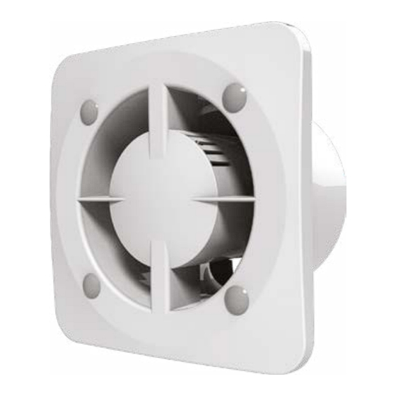
- Page 1 Base AXIAL FAN USER’S MANUAL www.ventilation-system.com...
-
Page 2: Table Of Contents
CONTENTS Delivery set ................................................8 Brief description ..............................................8 Operation guidelines ............................................8 Designation key ..............................................9 Installation and set-up............................................. 11 Connection to power mains ........................................13 Electronics operation algorithm ....................................... 15 Technical maintenance ..........................................16 Troubleshooting ..............................................17 Storage and transportation regulations ....................................17 Manufacturer’s warranty .......................................... - Page 3 This unit is not intended for use by persons (including children) with reduced physical, sensory or mental capabilities, or lack of experience and knowledge, unless they have been given supervision or instruction concerning use of the unit by a person responsible for their safety.
- Page 4 Connection to the mains must be made through a disconnecting device, which is integrated into the fixed wiring system in accordance with the wiring rules for design of electrical units, and has a contact separation in all poles that allows for full disconnection under overvoltage category III conditions.
- Page 5 Ensure that the unit is switched off from the supply mains before removing the guard. All operations described in this manual must be performed by qualified personnel only, properly trained and qualified to install, make electrical connections and maintain ventilation units. Do not attempt to install the product, connect it to the mains, or perform maintenance yourself.
- Page 6 Do not use the unit in a hazardous or explosive environment containing spirits, gasoline, insecticides, etc. Do not close or block the intake or extract vents in order to ensure the efficient air flow. Do not sit on the unit and do not put objects on it.
- Page 7 The Company reserves the right to modify the technical characteristics, design, or configuration of its products at any time in order to incorporate the latest technological developments. Never touch the unit with wet or damp hands. Never touch the unit when barefoot. BEFORE INSTALLING ADDITIONAL EXTERNAL DEVICES, READ THE RELEVANT USER MANUALS.
-
Page 8: Delivery Set
DELIVERY SET — 1 pc. Screws and dowels — 4 pcs. Plastic screwdriver (only for the models with a timer T) — 1 pc. User’s manual — 1 pc. Packing box — 1 pc. BRIEF DESCRIPTION The unit described herein is an axial fan for exhaust ventilation of small to medium-sized premises heated during winter. The fan design can also include a non-return valve to prevent back flow when the fan is switched off. -
Page 9: Designation Key
DESIGNATION KEY 100 Base V K Q (220V/60Hz) Power supply parameters other than 220 V/50 Hz _ – 220-240 V/50 Hz (by default) (220V/60Hz) – 220 V/60 Hz (12 V/50 Hz) – 12 V/50 Hz Motor modification: L – motor on ball bearings Turbo –... - Page 10 Model D [mm] B [mm] N [mm] L [mm] H [mm] C [mm] 100 Base (-I) 125 Base (-I) 150 Base (-I)
-
Page 11: Installation And Set-Up
INSTALLATION AND SET-UP Cut off power supply and make sure Remove the front panel of the fan by Mark the holes for fixing the fan and electricity has been turned off. turning it counter-clockwise. the power cable. Lead the power cable to the Fix the fan with the screws. - Page 12 Installation sequence for the decorative panel of the fan To install the decorative panel on the Install the mounts and the decorative Supply power to the fan. fan, remove the plugs. panel. The decorative panel is not included in the delivery set, and is purchased separately for the fan. R 600 The unit with a protection rating against access to hazardous parts and water ingress IP24 is allowed to be installed in zones...
-
Page 13: Connection To Power Mains
CONNECTION TO POWER MAINS Terminal designations on wiring diagrams: LT— timer control line — line — ON\OFF switch QF— automatic circuit breaker — neutral Base(-I) Base(-I) VT/VTH 2min 30min... - Page 14 Base(-I) T/TH 2min 30min Base(-I) V DO NOT USE A METAL SCREWDRIVER, KNIFE, ETC. FOR ADJUSTMENT OPERATIONS NOT TO DAMAGE THE CIRCUIT BOARD...
-
Page 15: Electronics Operation Algorithm
ELECTRONICS OPERATION ALGORITHM The fan with the timer T is started after actuation of the external switch, e.g. the light switch. The control voltage is supplied to the input terminal LT (ST). After the control voltage is off, the fan continues to operate within the set time period adjustable from 2 to 30 minutes by the timer. -
Page 16: Technical Maintenance
TECHNICAL MAINTENANCE The fan maintenance periodicity is at least once per 6 months. Maintenance steps: Disconnect the fan from power supply and make sure Clean the fan with a soft dry cloth or a brush. electricity has been turned off. Remove the front panel. Wash the front panel under running water. -
Page 17: Troubleshooting
TROUBLESHOOTING Problem Possible reasons Troubleshooting Make sure the power supply line No power supply. is connected correctly, otherwise When the unit is connected to power mains, the fan does not rotate and troubleshoot the connection error. does not respond to any controls. Internal connection fault. -
Page 18: Manufacturer's Warranty
MANUFACTURER’S WARRANTY The product is in compliance with EU norms and standards on low voltage guidelines and electromagnetic compatibility. We hereby declare that the product complies with the provisions of Electromagnetic Compatibility (EMC) Directive 2014/30/ EU of the European Parliament and of the Council, Low Voltage Directive (LVD) 2014/35/EU of the European Parliament and of the Council and CE-marking Council Directive 93/68/EEC. - Page 19 • Redesign or engineering changes to the unit. • Replacement and use of any assemblies, parts and components not approved by the manufacturer. • Unit misuse. • Violation of the unit installation regulations by the user. • Violation of the unit control regulations by the user. •...
- Page 20 Quality Inspector’s Stamp Sold by (name and stamp of the seller) Manufacture Date Purchase Date...
- Page 24 Certificate of acceptance ___________________________________________ The fan is recognized as serviceable. V160-1EN-07...
Need help?
Do you have a question about the 100 Base-I and is the answer not in the manual?
Questions and answers