Table of Contents
Advertisement
Quick Links
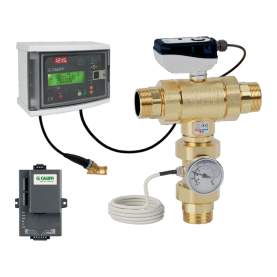
LEGIOMIX ® electronic mixing valve
© Copyright 2021 Caleffi
INSTALLATION AND COMMISSIONING MANUAL
Connect to 24 VAC
power source
www.caleffi.com
Function
The electronic mixing valve is used in centralized
systems that produce and distribute domestic hot
water. It maintains the temperature of the domestic hot
water delivered to the user when there are variations
in the temperature and pressure of the hot and cold
water at the inlet or in the draw-off flow rate. The
LEGIOMIX ® electronic mixing valve provides precise
temperature control over very low and very high flow
rate demand, minimal pressure drop with a ball valve
control element, automatic self-cleaning to prevent
scale formation and easy-to-use digital interface with
data logging, alarming and status indication. The
LEGIOMIX electronic mixing valve is furnished with
a controller with LCD user interface that provides a
set of programs for circuit thermal disinfection to kill
Legionella. The controller is configurable via keypad,
or local or remote computer. Depending on the type
of system and habits of the user, temperature levels
and operation times can be programmed as desired.
In addition, it comes standard with monitoring and
remote control connections.
The LEGIOMIX 6000 series electronic mixing valve
is powered by 24 VAC. (Caleffi provides a 115 / 24
VAC transformer in the package.) It is ICC-ES certified
to ASSE 1017 and CSA B125.3. It complies with
codes IPC, IRC, NPC and UPC for use in accordance
with the US and Canadian plumbing codes, and
standard NSF/ANSI 372, low lead. Also, it meets
the requirement of CSA Z317.1 Special Requirement
for Plumbing Installations in Health Care Facilities,
certifed by ICC-ES.
.
1
H0002997.08
6000 series
Advertisement
Table of Contents

Related Manuals for CALEFFI LEGIOMIX 600094A


Summary of Contents for CALEFFI LEGIOMIX 600094A
- Page 1 In addition, it comes standard with monitoring and remote control connections. The LEGIOMIX 6000 series electronic mixing valve is powered by 24 VAC. (Caleffi provides a 115 / 24 VAC transformer in the package.) It is ICC-ES certified to ASSE 1017 and CSA B125.3. It complies with...
-
Page 2: Safety Instruction
SAFETY INSTRUCTION This safety alert symbol will be used in this manual to draw attention to safety related instructions. When used, the safety symbol means ATTENTION! BECOME ALERT! YOUR SAFETY IS INVOLVED! FAILURE TO FOLLOW THESE INSTRUCTIONS MAY RESULT IN A SAFETY HAZARD. CAUTION: All work must be preformed by qualified personnel trained in the proper application, installation, and maintenance of systems in accordance with all applicable codes and ordinances. -
Page 3: Consigne De Sécurité
CONSIGNE DE SÉCURITÉ Ce symbole d'avertissement servira dans ce manuel à attirer l'attention sur la sécurité concernant instructions. Lorsqu'il est utilisé, ce symbole signifie. ATTENTION! DEVENEZ ALERTE ! VOTRE SÉCURITÉ EST EN JEU ! NE PAS SUIVRE CES INSTRUCTIONS PEUT PROVOQUER UN RISQUE DE SECURITE. ATTENTION: Tous les travaux doivent être effectués par du personnel qualifié... -
Page 4: Product Range
WARNING: This product can expose you to chemicals including lead, which is known to the State of California to cause cancer and birth defects or other reproductive harm. For more information go to www.P65Warnings.ca.gov. AVERTISSEMENT: Ce produit peut vous exposer à des produits chimiques comme le plomb, qui est connu dans l’État de Californie pour causer le cancer, dommages à... - Page 5 Controller, LCD user interface/display Materials: - Housing: self-extinguishing ABS, color white RAL 1467 - Cover: self-extinguising SAN, smoked transparent Electric supply: 24 VAC (min 21.6, max 26.0 VAC)- 50/60 Hz (115/24 VAC transformer included in package) Power consumption: 6.0 VA Adjustment temperature range: 70 - 185°F (20 - 85°C) Disinfection temperature range:...
-
Page 6: Characteristic Components
CONSULT TECHNICAL BROCHURE 1086 FOR COMPLETE GUIDANCE ON SIZING AND SELECTION. (1) To ensure stable operation and a ± 3° F accurate temperature control. Minimum flow rate is 0 gpm when recirculation flow rate is greater than or equal to the valve size minimum flow rating. (2) Suggested maximum flow rate for optimum modulating control (at 7.5 psid pressure drop). - Page 7 Operating principle The electronic mixing valve mixes hot water from storage and cold water from the main supply to maintain a constant controlled set temperature of mixed water at the outlet. The controller measures the temperature of the mixed water at the valve outlet with temperature sensor and modulates the mixing valve position to maintain the desired set temperature.
- Page 8 FLUSH VALVES Relay 4 (reduce temperature) 2nd THERMOSTAT Relay 3 (aquastat) Relay 2 ALARM (unsuccessful disinfection cycle) Relay 1 RECIRC PUMP (disinfection) Mixed °C Return °C TUESDAY 1 / 02/ 2017 ADJUSTMENT IN PROGRESS Shock Menu OPTIONAL MODBUS/ BACNET GATEWAY 24 VAC RELAY 1, 2, 3, 4 24 VAC FLOATING CONTROL...
-
Page 9: Back Panel
Back panel To remove the electrical wiring base, turn it round and extract it from its housing. Mixing valve fuse Appliance fuse 1 A - 250 V delayed 400 mA - 250 V delayed Closes PIN code Common disabling button Opens Earth Earth... -
Page 10: Temperature Sensor Resistance Values
Temperature sensor resistance values ºF ºC Ω ºF ºC Ω ºF ºC Ω ºF ºC Ω 100254 15310 3049 72937 11882 2489 53669 9297 2044 39919 7333 1688 32648 5827 1402 26100 4664 1171 19900 3758 Location of cable connectors To remove the electrical wiring base, turn it round When making... - Page 11 Connection cable cross-sections and lengths for circuit board wiring Unsheathing (in/mm) Cable seal No. Cable type including stripping 3 x AWG 16 5 / 130 6 x AWG 18 6 / 150 2 x AWG 18 8.25 / 210 2 x AWG 18 8.25 / 210 3 x AWG 18 8.25 / 210...
- Page 12 Front panel Mixed °C Return °C THURSDAY 10/12/ 2017 ADJUSTMENT RUNNING Shock Menu Cut the wires of the auxiliary microswitch (if not used) and insulate electrically before wiring (colors: white, green and red). 1. LCD display* 5. LED display: Treturn - return water 2.
-
Page 13: Led Indicators
Indication description Indications on LED display LED indicators 3 LED displays on the front of the controller The following LED indicators are located on the front show the clock time and termperature of the of the controller: mixed outlet water temperature and return tem- perature sensors at all times. -
Page 14: Operating Status
Operating status Depending on the times and the programs that have been set, the controller may be in one of the following operating modes.: • Adjustment; • Disinfection; • Flushing; • Thermal shock (this function has #1 priority over other modes) In the event of trouble due to the LEGIOMIX or the system, the device manages and reports the alarm and, depending on the situation, may maintain operation or not. -
Page 15: Low Power
Confirming disinfection If, within the time span (Time OFF - Time ON), the actual disinfection time reaches tDIS is greater than the set tMIN, the disinfection is concluded with a positive outcome. It automatically exits this status and returns to the adjustment (modulating) mode. If the sufficient time tDIS is not reached, the disinfection phase ends at Time OFF. - Page 16 Reset On the back panel, there is a specific reset button, in case it is necessary to retore the initial settings. If the date and time are not set after the reset, the controller will operate according to the factory default settings. Actuation relays The circuit board and terminals show the relay contacts used to manage auxiliary equipment and to report alarms.
- Page 17 Programs The operation of the controller during disinfection can be set according to different programs, selected depending on the type of system and management of the system. Set the program, and the day and time to turn on and turn off disinfection, in parameters in SETTINGS. Program 0 Features continuous mixed outlet water temperature modulation with automatic disinfection in a time band that can be set.
-
Page 18: Thermal Disinfection
Thermal disinfection The temperatures and corresponding disinfection times for the network must be chosen according to the type of system and the related intended use. The following criteria is generally followed, guided by..T = 160º F (70º C) for 10 minutes T = 150º... -
Page 19: Remote Control
Contact Caleffi for list of registers (points) for mapping LEGIOMIX information to ModBus. Configuation, mapping, hardware (routers, modem, etc.), and software are customer/user responsibility. Code NA10520... -
Page 20: Operating Parameters
Operating parameters The operating parameters can be set in the appropriate menus, and are summarized below: Summary of parameters. Setting ranges and factory (default) configuration. Factory (default) Parameter Description Setting Range configuration I-E-F-D-ES-P-NL- Language Language shown on LCD display ENGLISH SL-HR-SR-RO Date/Time For Disinfection phase and log entries... -
Page 21: Thermal Shock
100 sec in 2 sec steps Consult Caleffi otherwise. (This is NOT motor stroke time) Ball rotation cycle to clean deposit formation for ANTI-CLOG efficient operation. To deactivate enter release code 5566 and confirm with ON-OFF. - Page 22 The “log” is a FIFO (First In - First Out, loop buffer) that is continually updated and records parameters relating to adjustment and disinfection phases that occurred during the day. Data are stored for the last 40 days, after which the data for the first day are overwritten, etc. The hourly average mixed outlet and return water termperatures are save to Eeprom every hour, and alarms are saved at the time they occur.
- Page 23 Deleting the Log HISTORIC 06/ 04/ 2005 HISTORIC 06/ 04/ 2005 HISTORIC 06/ 04/ 2005 t DIS 060’ PGRM 1A H 001 002 003 004 H 007 008 009 010 MAX 130° T MIN 120 ° --- --- 120 120 120 122 --- --- 116 116 116 116 ALARM -- - 4 5-7-...
- Page 24 Menu structure table L e v e l 1 L e v e l 2 L e v e l 3 B u t t o n fu n c t io n s L A N G U A G E S E L L A N G U A G E S E L E - F - D - E S - P - NL - DOWN + OK...
- Page 25 Operability after alarm (page 1) Type of alarm P rogram Indic ation by alarm L E D Indic ation by L E D dis play Dis play on L C D R ec ording in log 0 1A 1B 2 G eneric alarm LE D comes Alarm shown on LE D display.
- Page 26 Operability after alarm (page 2) R elay s tatus Operating s tatus R elay 2 closed (if no alarms, In safe mode. Mixing valve closes, i.e. only cold water enters. the relay is normally open). Adjustment or disinfection or thermal shock is cancelled. All alarm indications are cleared when the cause of the alarm has been removed.
- Page 27 H0002995 www.cale .com MODBUS Registers LEGIOMIX ® RS485/MODBUS-RTU ° C FUNCTION REG (hex) DESCRIPTION VALUE 0x03 0x06 0000 Product type Code to de ne the product 6001 0001 BUS address 1…247 0002 T mix (°C) 0003 T rec (°C) 0004 T mix (°F) 0005 T rec (°F)
- Page 28 4= Friday FUNCTION REG (hex) DESCRIPTION 5= Saturday VALUE 0x03 0x06 6= Sunday 0000 Product type Code to de ne the product 0021 Active functions 6001 b0: Presence of recirc. probe 0001 BUS address 1…247 b1: Anticlog b2:0 b3:0 = Legal hour OFF b2:1 b3:0 = Legal hour EU b2:0 b3:1 = Legal hour US b2:1 b3:1 = Legal hour CUST 0002 T mix (°C)
-
Page 29: Plumbing Installation
Always install strainers of appropriately sized capacity at the inlet from the water main supply. Caleffi LEGIOMIX electronic mixing valves must be installed as shown be- low, conforming to applicable codes, and installed either vertically or horizontally, but the actuator must never be oriented upside down. - Page 30 Maintenance During service, regularly monitor the performance of the LEGIOMIX electronic mixing valve since any loss of performance may indicate maintenance is needed for the valve or the system. If the temperature of the mixed water is found the have changed significantly compared to previous recordings, refer to installation and commissioning sections.
- Page 31 Application diagrams Recirculation not connected to tank Non-return valve Ball valve Temperature gauge preventer Pump Expansion vessel Thermostat Safety relief valve Strainer Clock Recirculation connected to tank...
- Page 32 SYSTEMS”. WHEN INSTALLED AND USED AS DESIGNED AND INTENDED, THE LEGIOMIX CAN HELP REDUCE BACTERIA IN DOMESTIC HOT WATER RECIRCULATION SYSTEMS, HOWEVER DUE TO SYSTEM-DEPENDENT VARIABLES, 100% ERADICATION CAN NOT BE GUARANTEED. CALEFFI IS NOT RESPONSIBLE FOR ANY DAMAGES, CONSEQUENTIAL OR OTHER, THAT MAY ARISE FROM LEGIONELLA ILLNESS WHEN USING THE LEGIOMIX ELECTRONIC MIXING VALVE.
Need help?
Do you have a question about the LEGIOMIX 600094A and is the answer not in the manual?
Questions and answers