CALEFFI 6000 Series Installation And Commissioning Manual
Hybrid electronic mixing valve
Hide thumbs
Also See for 6000 Series:
- Installation and commissioning manual (29 pages) ,
- Programming manual (20 pages) ,
- Quick start manual (4 pages)
Table of Contents
Advertisement
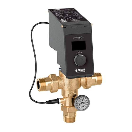
Hybrid electronic mixing valve
© Copyright 2017 Caleffi
Operating principle
The electronic hybrid mixing valve combines the typical function
of the mechanical thermostatic mixing valve and the management
efficiency of an electronic mixing valve in a single device.
The thermostatic mixing valve uses the mechanical action
performed by the internal control thermostatic element, which
responds promptly to any variation in temperature, pressure and
inlet flow rate to quickly restore the mixed water temperature value
at the outlet.
This standard mixing valve is effectively handled by a motorised
actuator that, upon the signal coming from the temperature probes
and under the control of a specific regulator, changes the mixed
water temperature set position.
The electronic regulator, directly on the actuator, allows the
mixed water temperature control according to different functional
programs, both for normal control and for the thermal disinfection
for the prevention of Legionella.
An optional memory system allows recording every minute of flow
temperature, return temperature, alarm and functional statuses,
useful for monitoring the operating status of the entire system.
Appropriate relays are used to manage the alarms and external
appliances, for example for loading accumulation hot water and
switching on/off the recirculation pump.
The regulator is fitted for remote control with specific transmission
protocols such as MODBUS, through optional board, for use in
Building Management Systems (BMS).
The device is provided with CE mark in accordance with
directives 2014/35/EU and 2014/30/EU.
6000 Series LEGIOMIX 2.0
CONTENTS
Probes connection
1
H0002123
www.caleffi.com
2
3
4
5
6
7
8
9
10
11
12
Advertisement
Table of Contents

Related Manuals for CALEFFI 6000 Series


Summary of Contents for CALEFFI 6000 Series
-
Page 1: Table Of Contents
H0002123 www.caleffi.com Hybrid electronic mixing valve 6000 Series LEGIOMIX 2.0 © Copyright 2017 Caleffi INSTALLATION AND COMMISSIONING MANUAL CONTENTS Product range Characteristic components Package content Technical specifications Operating principle Application diagram Regulator-actuator Wiring diagrams Electronic boards description Cables pathway Cables wiring and positioning... -
Page 2: Installation And Commissioning Manual
Product range 6000 series Hybrid electronic mixing valve Sizes DN 15 (1/2”), DN 20 (3/4”), DN 25 (1”), DN 32 (1 1/4”), DN 40 (1 1/2”), DN 50 (2”) Technical specifications Characteristic components Valve body Materials: Body: dezincification-resistant alloy EN 1982 CC770S... -
Page 3: Operating Principle
Operating principle At the inlets the mixing valve has the hot water from the storage and the cold water from the water mains. At the outlet there is the flow mixed water. By means of a specific probe, the regulator measures the temperature of the mixed water at the valve outlet and actuates an obturator in order to maintain the setting. -
Page 4: Regulator-Actuator
Regulator-actuator Battery installation Before connecting the power supply, insert the battery supplied, type CR 2032. The presence of the battery allows the clock continuous updating. In case of low or missing battery, if there is no network, the device does not ensure that the time and date are stored and therefore that the programmed disinfections are executed correctly. -
Page 5: Electronic Boards Description
Electronic boards description CS176 - Electric supply and relay CS180 - Contacts and probes The following connection inputs are on the board: The following connection inputs are on the board: - L/N = Power supply 230 V 50/60 Hz - IN1 = NO (normally open) potential-free... -
Page 6: Cables Pathway
Cables pathway Mimimum dimensional characteristics to respect for board electric connections: connection cable cross sections and lengths. Observe the applicable regulations in force in the country of installation. UNSHEATHING UNSHEATHING BOARD TERMINAL CABLE TYPE IN mm (L) POS. A * IN mm (L) POS. -
Page 7: Recommended Minimum Distances
Connection of probes: Probe resistance table If necessary for the installation, Ω Ω °C Ω °C Ω °C °C the cable connecting the flow and 12493 97060 2488 return probes with the controller must be installed in a raceway. If the 72940 10000 2083... -
Page 8: Front Panel
Disinfection Front panel In this mode, the device performs thermal disinfection, which consists in raising the mixed water temperature for a defined period of time. The following can be set: - Days of the week for performing the disinfection - Minimum disinfection temperature - Disinfection start time - Minimum stay time above the minimum disinfection temperature in order to evaluate the successful outcome of the disinfection... -
Page 9: Plumbing Installation
Plumbing installation Before installing the Caleffi mixing valve, the pipes must be flushed to prevent impurities in the water from affecting performance. The following are indicated on the body of the mixing valve: - H hot water inlet - C cold water inlet - MIX mixed water outlet In systems with mixing valves, check valves must be installed to prevent undesired backflow. -
Page 10: Thermal Disinfection
On the system log book, record all operations carried out. Troubleshooting In normal operating conditions, Caleffi series 6000 hybrid electronic mixing valves provide outstanding performance. However, in special circumstances when our maintenance schedule is not observed, the following problems may arise:... -
Page 11: Regulator-Actuator Replacement/Rotation
Regulator-actuator replacement/rotation In case of replacement of the regulator-actuator it is necessary to remove all electric connections and perform the following operations: Max 4 N • NOTE: Following the above operations, perform the zero and full scale acquisition. Thermostatic function In case of motor failure or power failure, the device is able to guarantee the temperature adjustment through the thermostatic element. -
Page 12: Application Diagrams
Application diagrams Non-return valve Ball valve Temperature gauge Pump Expansion vessel Thermostat Safety relief valve Strainer Clock LEAVE THIS MANUAL AS A REFERENCE GUIDE FOR THE USER...
Need help?
Do you have a question about the 6000 Series and is the answer not in the manual?
Questions and answers