CALEFFI 6000 Series Installation And Commissioning Manual
Electronic mixing valve with programmable thermal disinfection
Hide thumbs
Also See for 6000 Series:
- Installation and commissioning manual (29 pages) ,
- Programming manual (20 pages) ,
- Quick start manual (4 pages)
Table of Contents
Advertisement
Electronic mixing valve with programmable thermal disinfection
© Copyright 2020 Caleffi
Function
The electronic mixing valve is used in centralised
systems that produce and distribute domestic hot
water.
Its function is to guarantee and maintain the
temperature of the domestic hot water delivered to
the user when there are variations in the temperature
and pressure of the hot and cold water at the inlet
or in the draw-off flow rate.
This particular series of electronic mixing valves
is equipped with a specific regulator that
controls a set of programs for circuit thermal
disinfection against Legionella.
It also allows checking that the thermal
disinfection temperature and time are actually
reached and means the appropriate corrective
action can be taken. All the parameters are
updated every day and logged, with temperatures
recorded every hour.
Depending on the type of system and habits of
the user, it is possible to program temperature
levels and operation times in the most appropriate
manner.
It is fitted for remote control with specific MODBUS-
RTU transmission protocols, for use in Building
Management Systems (BMS).
INSTALLATION AND COMMISSIONING MANUAL
Series 6000 (24 V)
CONTENTS
Warnings
Product range
1
H0006862.01
www.caleffi.com
2
3
4
5
6
11
12
13
14
15
18
19
20
21
Advertisement
Table of Contents

Related Manuals for CALEFFI 6000 Series


Summary of Contents for CALEFFI 6000 Series
-
Page 1: Table Of Contents
H0006862.01 www.caleffi.com Electronic mixing valve with programmable thermal disinfection Series 6000 (24 V) © Copyright 2020 Caleffi INSTALLATION AND COMMISSIONING MANUAL CONTENTS Warnings Product range Characteristic components Package content Technical specifications Operating principle Digital regulator Operating status Function The electronic mixing valve is used in centralised... -
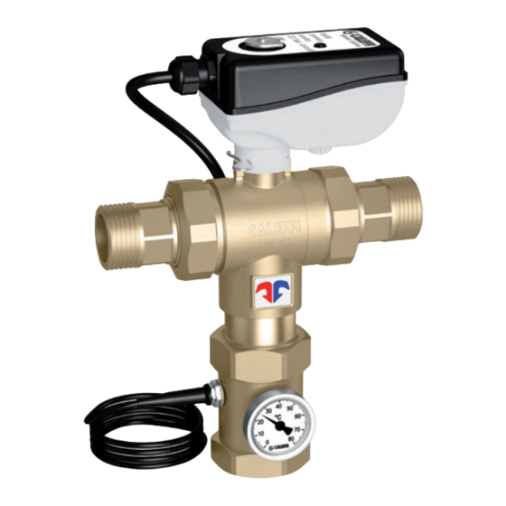
Page 2: Characteristic Components
The language can always be changed via the “settings” menu. Product range 6000 Series Electronic mixing valve with programmable thermal disinfection. Threaded version. sizes DN 20 (3/4”) - DN 25 (1”) - DN 32 (1 1/4”) - DN 40 (1 1/2”) - DN 50 (2”) 6000 Series Electronic mixing valve with programmable thermal disinfection. -
Page 3: Package Content
Package content • Digital regulator, consisting of housing and base for electrical connection • DIN bar and wall anchors • Mixing valve • Actuator • Flow probe • Return contact probe. Return probe with pocket (optional) code F69381 (not supplied as standard) •... -
Page 4: Technical Specifications
Technical specifications Digital regulator Material: Valve body Housing: self-extinguishing ABS, Materials: white RAL 1467 Body: - threaded versions: brass EN 12165 CW617N Cover: self-extinguishing SAN, smoked transparent - flanged versions: “LOW LEAD” dezincification resistant alloy Electric supply: 24 V (ac) 50/60 Hz EN 12165 CW724R Power consumption: 6,5 VA... -
Page 5: Operating Principle
Operating principle At the inlets the mixing valve has the hot water from the storage and the cold water from the water mains. At the outlet there is the flow mixed water. By means of a specific probe, the regulator measures the temperature of the mixed water at the valve outlet and actuates the mixing valve in order to maintain the set temperature. -
Page 6: Digital Regulator
CALEFFI LEGIOMIX 5(2) A OPEN (Black) 250 V L - N: 230 V ~ 6,5 VA (Blue) Mixing valve 5(2) A CLOSE (B ro Wn ) 250 V Digital regulator Fuse 1 (Main) T 80 mA 250 V ~ To remove the electrical wiring base, turn it round and extract it from its housing. - Page 7 Back panel Mixing valve fuse 1 Appliance fuse 400 mA - A - 250 V delayed 250 V delayed Closes Common Opens Earth Earth Neutral Live Relay 4 RS-485 Relay 3 – Flow Relay 2 Common Return Thermal shock Relay 1 activation Battery Shock...
- Page 8 Location of cable seals When making the electrical connections, keep to the following sequence for wiring the terminal strip and tightening the cable seals: Mixing valve fuse 1 Applianc A - 250 V delayed 250 V d 1 Power supply* 2 Mixing valve control* 3 Flow probe* 4 Recirculation probe*...
- Page 9 Dimensional characteristics to respect for circuit board wiring: connection cable cross-sections and lengths Cable seal Unsheathing in mm Cable type including stripping (L) 6x0,75 2x0,75 2x0,75 3x0,75 2x1,5 2x1,5 2x1,5 2x1,5 Connections layout: connections must not create thrust stresses on the circuit board Front panel We recommend (if not used) cutting the wires for the auxiliary microswitch and electrically...
- Page 10 Indication description Indications on LCD display On the front of the appliance is a green backlit alphanumeric display Indications on LED display with four rows of 20 characters each, for setting parameters, scheduling On the front of the appliance are 3 LED displays, which show the clock operations, displaying error messages and machine status.
-
Page 11: Operating Status
Operating status Depending on the times and the programs that have been set, the appliance may be in one of the following operating modes: • Adjustment; • Disinfection; • Flushing; • Thermal shock (this function has priority over the previous ones); In the event of a trouble due to the appliance or the system, the device manages and reports the alarm and, depending on the situation, may maintain operation or not. -
Page 12: Programs
Programs The operation of the regulator during disinfection can be set according to different programs, selected depending on the type of system and its management: Program 0 This program features continual adjustment of the flow temperature with automatic disinfection in a time band that can be set. With this program the return probe is not used;... -
Page 13: Actuation Relays
Flushing The appliance goes into this mode automatically after the disinfection phase. It can be used, for example, to bring the water temperature back to the SET1 value, or periodically to clear possible residues from the storage. This phase is ended after a time selected with the tFLUX parameter. When the flushing time has ended, relay 1 and relay 4 are deactivated and the appliance returns to the “adjustment”... -
Page 14: Operating Parameters
8 to 320 s 0100 s to the fully open position. Recommended default value. Contact in steps of 2 s Caleffi. (Not the physical operating time). ANTI-CLOG Ball rotation cycle for cleaning deposits. ON / OFF To deactivate it, enter code 5566 and confirm with ON-OFF. -
Page 15: Log
The “log” is a FIFO list (First In - First Out, loop buffer) that is continually updated and records parameters relating to adjustment and disinfection phases that occurred during the day. Data are stored for the last 40 days, after which the data for the first day are overwritten, and so on. The hourly average flow and return temperatures are saved to Eeprom every hour, whereas alarms are saved at the time they occur. - Page 16 Access PIN code Menu navigation can be prevented by enabling the keypad lock function. The keypad is then unlocked by entering a PIN code. If the lock function is enabled, the keypad is locked automatically after a timeout of 10 minutes starting from the last button press. When the keypad lock function is active, a padlock symbol appears on the working screen (see right): Also, if the lock function is active and a button is pressed while the working screen is displayed, the PIN code input screen appears: The code is entered by selecting the first digit using the “UP”...
- Page 17 Menu structure table Level 1 Level 2 Level 3 Button functions LANGUAGE SEL LANGUAGE SEL - F - D - ES - P - NL - DOWN + OK SL - HR - SR - RO When switching on, you will need to confirm the language. If the language is not selected within one minute, the menu will move on to the date and time setting procedure.
-
Page 18: Hydraulic Installation
Hydraulic installation Before installing the Caleffi mixing valve, the pipes must be flushed to prevent impurities in the water from affecting performance. We recommend always installing strainers of sufficient capacity at the inlet from the water main. If the system is washed with chemicals, leave the relevant flow temperature probe housing end plug on. -
Page 19: Maintenance
At least every 12 months, or more frequently if required. 1) Check and clean the strainers in the system. 2) Make sure that any check valves installed at the inlet of the Caleffi Relay Recirculation... -
Page 20: Manual Opening Procedure For Flanged Versions
Manual opening procedure for flanged versions To perform manual opening, in the case of a fault or power failure, proceed as follows: 1) Unscrew the threaded locking pin using a 19 mm wrench. 4) Pull the knob outwards. 2) Screw the specific lever (supplied) into the locking pin hole. 5) Rotate the valve to the desired position. -
Page 21: Alarm Management
Alarm management To make it easier to resolve any functional faults that occur after installation and commissioning, the regulator is configured so that faults are indicated by special alarms and the appropriate action is taken. In this case, the cause of the alarm is shown on the LCD display: If the alarm does not inhibit all the functions, the alarm screen will alternate with the appliance status screen. - Page 22 Operability table after an alarm Type of alarm Program Recording in log Indication by alarm LED Indication by LED Display on LCD display AL1: 0 1A 1B 2 “Generic alarm” LED Alarm shown on LED “Flow probe fault” alarm YES (AL1) Stored in the flow sensor comes on and “Status OK”...
- Page 23 Operating status Relay status Relay 2 closed (if no In safe mode. Mixing valve closes, i.e. only cold water enters. alarms, the relay is normally Adjustment or disinfection or thermal shock is cancelled. open). All alarm indications are cleared when the cause of the alarm has been removed. Relay 2 open.
- Page 24 Application diagrams Check valve Ball valve Temperature gauge Pressure reducing valve Pump Expansion vessel Thermostat Safety relief valve Strainer Clock LEAVE THIS MANUAL AS A REFERENCE GUIDE FOR THE USER. The user quick guide is inserted in the special compartment provided in the left part of the power unit.
Need help?
Do you have a question about the 6000 Series and is the answer not in the manual?
Questions and answers