CALEFFI LEGIOMIX 6000 Series Programming Manual
Hybrid electronic mixing valve
Hide thumbs
Also See for LEGIOMIX 6000 Series:
- Installation and commissioning manual (29 pages) ,
- Quick start manual (4 pages) ,
- Installation and commissioning manual (24 pages)
Table of Contents

Related Manuals for CALEFFI LEGIOMIX 6000 Series


Summary of Contents for CALEFFI LEGIOMIX 6000 Series
-
Page 1: Table Of Contents
H0004567.01 www.caleffi.com Hybrid electronic mixing valve 6000 series LEGIOMIX 2.0 © Copyright 2018 Caleffi PROGRAMMING MANUAL CONTENTS Front panel Display when switched on Date and time configuration Operating status Disinfection programs Disinfection activation with connection through inlet IN1 Interrupting disinfection... -
Page 2: Front Panel
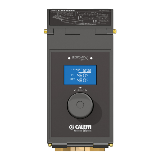
Front panel Display when switched on When the device is switched on, the green LED lights up and the following screen appears on the display. file originale After about 2 seconds, the battery control screen will appear on the display. 1) LED indicators: green LED on: mains LED fixed red LED: disinfection in progress, acquisition of full... -
Page 3: Operating Status
ginale ginale ginale - Insert the day turning the knob Operating status - Press the knob to confirm the day set During the operation of the device, the following work states can be ginale displayed: 1 - Reached setpoint 2 - Adjustment in progress 3 - Disinfection in progress 4 - Thermal shock in progress 5 - Zero and full scale acquisition... - Page 4 d) Opening limit switch reaching and T1<TSET. The mixer is unable to b) Disinfection in progress with control on return probe T2 (see table reach the set value even if it is in the maximum opening position; on page 5). therefore the following symbol is displayed.
-
Page 5: Disinfection Programs
Disinfection programs: Different programs can be set, chosen according to the type of system and its management: Disinfection type with flow probe T1 enabled Disinfection Code Description Disinfection performed at maximum available flow temperature, limited to the system maximum temperature set (T1 Hi). -
Page 6: Disinfection Activation With Connection Through Inlet In1
Example with ECO function enabled. Disinfection code: d1 - ECO function Flow temperature = Maximum available temperature Minimum disinfection time = automatic check Area where time is counted Flow temperature 60°C Disinfection is considered successful when the When the temperature drops below 60°C, the following conditions are continuously respected: countdown stops and resumes from zero when it Flow temperature ≥... - Page 7 The thermal shock is activated manually through the activation control SH in the "Controls Sub-menu". In this mode, the device raises the flow temperature to the set value for a certain period of time. The disinfection in progress OUT3 relay and the recirculation pump management OUT2 relay are always activated during the thermal shock.
-
Page 8: Operating Parameters And Default Values
Operating parameters and default values The operating parameters can be set in the appropriate menus, and are summarised in the following table: Factory (default) Parameter Description Setting range configuration “Installer Menu” access password 0000-9999 2222 Identifies the product among those connected from 1 to 255 to the BUS T1 = flow probe enabled... -
Page 9: Log
The device, through the optional data transmission board CS179 (code 600001) system allows recording the flow temperature, return temperature, alarms and functional statuses, useful for monitoring the operation status of the device. It will then be possible to export the data from the device through a PC interface. - Page 10 Display Menu: Temperature value measured by During the operation of the device, it is possible to enter the "Display probe T2. Menu" at any time pressing the knob and turning it clockwise or counterclockwise to navigate within the menu. Sub-menu. From this Alarms Display of six time bands that menu it is possible to display the...
- Page 11 Setting the maximum time available Programming Menu: within which it is possible to From any operation status, pressing the knob for 5 seconds, displays perform the thermal shock. the "Programming Menu". Access to the menu requires the Password. Default: 10 min RESET.
- Page 12 Set summer daylight saving time. Setting of the six time bands ON/OFF selection: activating that can be set for recirculation the ON option will enable the (OUT2 activation) function. Check the disinfection 1-02:00 and 05:59 4-14:00 and 17:59 programming. 2-06:00 and 09:59 5-18:00 and 21:59 3-10:00 and 13:59 6-22:00 and 01.59 Default ON Active default on all ranges...
-
Page 13: Controls Sub-Menu Alarms Sub-Menu
Sub-menu controls: Alarms sub-menu: In the “Display Menu”, when there is any alarm, there is In the menu there are the following functions: “Alarm Sub-menu”. From initial screen press knob, at its release the following screen will be displayed: Zero acquisition control. Perform with closed shut-off valves. -
Page 14: Alarm Management
Alarm management To make it easier to resolve any functional faults that occur after installation and commissioning, the device is configured so that faults are indicated by special alarms so as to take the appropriate action. The cause of the alarm is displayed in the status log. If the alarm does not inhibit all functions, only the "Maintenance" and "Manual” symbols will be shown on the display;... - Page 15 RELAY STATUS / WORK STATUS RECORDING POSSIBLE CAUSE REMEDY - "Reset alarms" control: The device performs the zero and full scale acquisition OUT1 NC = Closed to check that the stroke set is congruent, if it OUT2 = Open - OPERATING SCREW MECHANICAL BLOCK does not find mechanical blocks it resumes OUT3 = Open normal operation;...
- Page 16 ALARM CODE ALARM REPRESENTATION ALARM DESCRIPTION ALARM TYPE NON-BLOCKING ALARM: It does not perform the LOW BATTERY: AL06 disinfection if there is a voltage low battery indication failure with consequent loss of time setting NON-BLOCKING ALARM: ELECTRIC SUPPLY FAILURE: indicates that When the electric supply is AL07 there was an electric supply failure for more...
- Page 17 RELAY STATUS / WORK STATUS RECORDING POSSIBLE CAUSE REMEDY OUT1 NC = Closed - Replace the battery OUT2 = Closed if set - LOW BATTERY OUT3 = Open - Check the battery correct installation - Check electric supply mains. The alarm must be reset using the - MAINS BLACKOUT When the electric supply is resumed, the device "Reset alarms"...
Need help?
Do you have a question about the LEGIOMIX 6000 Series and is the answer not in the manual?
Questions and answers