Table of Contents
Advertisement
Quick Links
Advertisement
Table of Contents

Related Manuals for Onlogic Axial AC101

Summary of Contents for Onlogic Axial AC101
- Page 1 Axial AC101 Product Manual...
- Page 2 Revision History Date Revision History First release of Axial AC101 manual...
-
Page 3: Table Of Contents
Table of Contents 1 - System Overview 1.1 - Accessories 1.2 - Latest Drivers, Firmware, and Additional Information 1.3 - Product Specifications 1.4 - System Dimensions and Exterior Features 1.4.1 - System Dimensions 1.4.2 - Front I/O Ports 1.4.3 - Rear I/O Ports 1.4.4 - Front LEDs &... - Page 4 4.3.2 - Additional Fan Defaults 4.4 - Thermal Performance and Validation 4.4.1 - Test Conditions 4.4.2 - Test Results 5 - Power 5.1 - Supported Power Supplies 5.2 - Power Redundancy 5.3 - Wake-Up Events 6 - Operating Systems 6.1 - Windows 10 IoT Enterprise 2021 LTSC Licensing 7 - Mounting Hardware 7.1 - Rack Mounting 7.1.1 - Rackmount 23"...
-
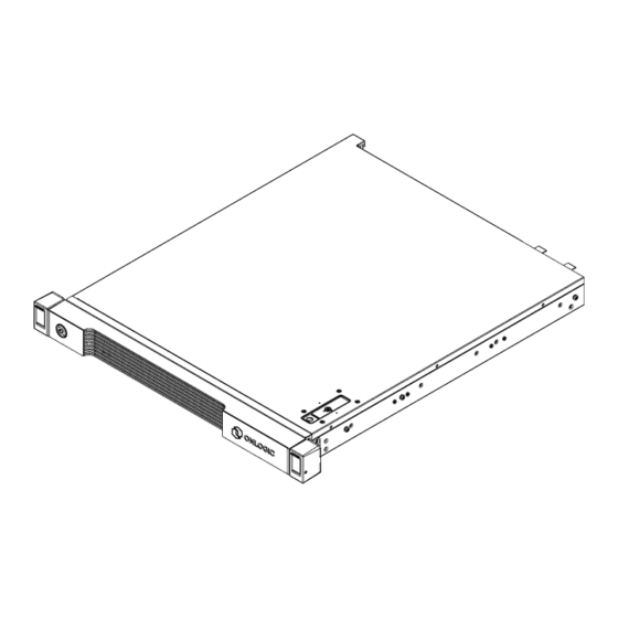
Page 5: System Overview
1 - System Overview Axial AC101 without Security Bezel Axial AC101 with Security Bezel... -
Page 6: Accessories
If additional items were purchased, such as rail mounting kits/brackets, they will be boxed separately. 1.2 - Latest Drivers, Firmware, and Additional Information Drivers, firmware, and product information can be found on the Axial 101 product page. For the latest information, visit the Axial 101 product page at: https://www.onlogic.com/ac101/ https://www.onlogic.com/eu-en/ac101/... -
Page 7: Product Specifications
1.3 - Product Specifications OnLogic Axial 100 Series Variants AC101 - High-Performance 1U with 150W PCIe 4.0 x16 Expansion Intel® 13th Gen Alder Lake-S (LGA1700) Core i3, i5, i7 & i9 up to 24-core 32-thread Processor i3-13100E or TE, i5-13500E or TE, i7-13700E or TE, i9-13900E or TE... - Page 8 Rack Mount 28” Toolless Slide Rail Rack Mount 23” Slide Rail Mounting Rack Mount 23” Slide Rail with Cable Management Arm Wall Mount 5°C ~ 40°C (ASHRAE A3 Operating Temperature) Operating Temperature Maximum ambient temperature decreases by 1°C for every 175m (574 ft) increase in altitude above 900m (2,953 ft) Storage Temperature -40°C ~ 70°C...
-
Page 9: System Dimensions And Exterior Features
1.4 - System Dimensions and Exterior Features 1.4.1 - System Dimensions Axial AC101 without Security Bezel Axial AC101 with Security Bezel... -
Page 10: Front I/O Ports
1.4.2 - Front I/O Ports 1.4.3 - Rear I/O Ports... -
Page 11: Front Leds & Buttons
1.4.4 - Front LEDs & Buttons LED / Button Color Blink Power White Device is on Device is off ID indicator ID indicator is ID indicator is Blue asserted deasserted blinking (Identification) (Reset) The ID LED/Button is available to assist with locating the system. ID may be physically turned On / Off by physically pressing the ID button. -
Page 12: Security Bezel
1.4.6 - Two Point Locking Lid with Intrusion Detection The Axial AC101 Edge Server chassis lid has a two point locking locking mechanism with an intrusion mechanism built natively into the system chassis. For the two point locking mechanisms, the first point is the top latch with a tamper resistant screw... - Page 13 The second lid locking point is a thumb screw located in the rear of the system. In the event that the system lid is removed while power is present to the system, the intrusion switch will detect this event and the Chassis Intrusion sensor will be asserted. Relative to the intrusion, this event will also be logged in the Baseboard Management Controller event log.
-
Page 14: System Label
The system label is located on the bottom of the chassis as depicted in the image below. The system label will contain the following information: System Model ● OnLogic Serial Number ● Regulatory & Compliance Certification Logos ● 1.6 - Front Service Label... -
Page 15: Motherboard Overview
1.7 - Motherboard Overview 1.7.1 - System Block Diagram... -
Page 16: Internal Motherboard Features & Headers
1.7.2 - Internal Motherboard Features & Headers... - Page 17 Item Description Item Description 2x SATA Header (SATA3_7)(Upper), Front VGA Header, (FRNT_VGA1), Unused (SATA3_6)Lower PWM Configuration Header (PWM_CFG1), System Front Panel Header (PANEL1) Unused 2x DDR5 DIMM Slots (DDR5_A1, DDR5_B1) Auxiliary Front Panel Header (AUX_PANEL1) ATX 12V Power Connector (ATX12V1) SATA SGPIO Connector (SATA_SGPIO1), Unused ATX 12V Power Connector (ATX12V2) SPI TPM Header (TPM_BIOS_PH1)
-
Page 18: I/O Definitions
2 - I/O Definitions 2.1 - Networking The Axial AC101 features the following onboard Ethernet ports: Port Chipset Capabilities Dedicated BMC Management port. Port is only used for system management Realtek functions such as IPMI, RedFish, Remote RTL8211F 1GbE Mgmt (Attached to Management, etc. -
Page 19: 1Gbe Dedicated Bmc Port Leds
2.2 - 1GbE Dedicated BMC Port LEDs Color State Condition No Link Link established Link Yellow Blinking Data activity 10Mbps data rate or no link Speed 100Mbps data Yellow rate Green 1Gbps data rate 2.3 - 1GbE Networking Port LEDs Color State Condition... -
Page 20: 10Gbe Networking Port Leds
2.5 - USB Ports There are 4 USB 3.2 Gen 1 Type A ports on the Axial AC101 Edge Server. Two ports are on the front of the system. Two ports are on the rear of the system. All USB ports also support USB 2.0 connectivity. -
Page 21: Primary Component Connectors
This expansion slot is capable of supporting PCIe Gen 3 x4 and is routed directly to the W680 PCH. This slot is designed to support NVMe storage drives. 3.2 - TPM Header The Axial AC101 supports an optional discrete TPM 2.0 module. -
Page 22: Sata Headers
The data ports support SATA III 6Gbps storage devices. 3.4 - OCuLink Headers There are four OCuLink headers on the Axial AC101 Edge Server motherboard that support PCIe 4.0 x4 connections to enable NVMe drives. 3.5 - PCIe Gen 4.0 x16 Slot The Axial AC101 features one PCIe Gen 4.0 x16 connector on the motherboard which is accessible... -
Page 23: Dual-Channel Symmetric Mode (Interleaved Mode)
Dual-Channel Symmetric mode is fully interleaved and provides the maximum performance. The Axial AC101 will default to Dual-Channel Symmetric mode when both Channel A and Channel B DIMM connectors are populated in any order, with the total amount of memory in each channel being the same. -
Page 24: Dimm Population Requirements
3.6.2 - DIMM Population Requirements The following rules apply to when populating DIMMs in the Axial AC101 Edge Server 1. Only DDR5 DIMMs may be installed into the system. 2. The maximum frequency of the system memory will never exceed that of the lowest frequency DIMM DIMM(s) installed in the system. -
Page 25: Thermals And Cooling
4 - Thermals and Cooling The Axial AC101 Edge Server is designed to operate and function across a wide temperature (5 to 40°C) and humidity range (8 to 85% RH non-condensing). The following sections describe the thermals and cooling capabilities and behavior of the system. -
Page 26: Temperature Sensors
4.2 - Temperature Sensors Temperature sensor data is available for a number of onboard temperature sensors. Upper Non Critical Upper Critical Sensor Name Temperature °C Temperature °C TEMP_MB TEMP_CPU TjMax - 1 TjMax TEMP_VR TEMP_CARD_SIDE TEMP_X710 TEMP_TR1 TEMP_M.2 TEMP_GPU... -
Page 27: Default Fan Settings
4.3 - Default Fan Settings The system is configured to operate in accordance with a closed loop thermal algorithm which accommodates for components temperature maximums, reduced acoustics, lower power consumption, and optimal performance. 4.3.1 - Fan Zone Assignments The fan zone assignments, default closed loop tables, and associated temperature sensors are outlined in this section. -
Page 28: Fan Zone 2 - Pcie / Gpu Area
As per the default configuration settings, the system fans will increase duty cycle at 3% increments every 1 seconds when the CPU temperature is at or above 80°C. When the temperature drops below 75°C, the system fan duty cycle will reduce 3% every 3 seconds. 4.3.1.2 - Fan Zone 2 - PCIe / GPU Area Assigned Temperature Sensor: TEMP_GPU Assigned Fans: FAN1, FAN2... -
Page 29: Additional Fan Defaults
Note: GPU temperature sensing is only supported with Nvidia professional grade GPUs 4.3.2 - Additional Fan Defaults The default system idled duty cycle is 5%. Upon System Fan Failure or BMC Firmware Update, System Fans will ramp to maximum speed. 4.4 - Thermal Performance and Validation As previously noted, the default fan duty and configuration settings have been validated to operate in accordance with the supported temperature range (up to 40°C) as per the following test scenario and... - Page 30 Discrete GPU loaded with Nvidia Nbody ○...
-
Page 31: Test Results
4.4.2 - Test Results The AC101 system sustained a full processor workload and 80% workloads on memory, storage and 3D graphics, along with executing an Nbody simulation through its full rated temperature range without throttling and while maintaining greater than base clocks on all processor cores and GPU cores. -
Page 32: Power
5 - Power The sections below focus on the power features and capabilities of the Axial AC101 Edge Server. 5.1 - Supported Power Supplies The system supports two redundant power supplies, which may either be 450W or 750W. These power supplies are hot-swappable, meaning they can be replaced while the system is running without interrupting its operation. -
Page 33: Wake-Up Events
Once the replacement power supply is installed, the system will automatically detect it and bring it online, restoring full redundancy. 5.3 - Wake-Up Events Axial AC101 supports multiple power states. Wake-Up Event From ACPI State... -
Page 34: Operating Systems
6 - Operating Systems The Axial AC101 Edge Server supports the following operating systems: Microsoft Windows 10 IoT Enterprise 2021 LTSC Value (Celeron/i3/i5) - 64 Bit ● Microsoft Windows 10 IoT Enterprise 2021 LTSC High End (i7/i9/Xeon) - 64 Bit ●... -
Page 35: Mounting Hardware
7 - Mounting Hardware The Axial AC101 Edge Server has been designed with flexibility in mind and can be mounted in different ways. As the system is designed to meet industry standard 19” Electronic Industries Alliance (EIA) racks, there are multiple rack mounting rail kits available. Additionally, the system may also be wall mounted using the OnLogic wall mount kit. -
Page 36: Rackmount 23" Ball Bearing Cable Management Arm Slide Rail Kit
7.1.2 - Rackmount 23" Ball Bearing Cable Management Arm Slide Rail Kit The 23" Ball Bearing Cable Management Arm Slide Rail Kit is an optional accessory that enhances the standard ball bearing slide rail options by providing a cable management arm to neatly organize and secure cable connections to the Edge Server system while still supporting easy removal of the server from the rack for maintenance and upgrades. -
Page 37: Rackmount 28" Simple Locking Ball Bearing Slide Rails
7.1.3 - Rackmount 28" Simple Locking Ball Bearing Slide Rails The 28” Simple Lock Ball Bearing Slide Rails are an optional accessory designed to enhance the functionality and ease of use of the Edge Server. These slide rails are designed to be used with standard 19"... -
Page 38: Wall Mounting
7.2 - Wall Mounting 7.2.1 - Wall mount kit The Axial AC101 Edge Server wall mount kit is made of sturdy metal and designed to securely hold the server in place against a wall. This optional accessory includes the necessary wall mounting brackets and hardware to flexibly mount the Axial AC101 Edge Server system where a rack is not available or practical. -
Page 39: Regulatory Compliance
8 - Regulatory Compliance 8.1 - CE The computer system was evaluated for IT equipment EMC standards as a class A device. The computer complies with the relevant IT equipment directives for the CE mark. Modification of the system may void the certifications. Testing includes: EN 55032, EN 55035, EN 60601-1, EN 62368-1, EN 60950-1. -
Page 40: Appendices
Additional technical support and information can be found on our support website at the following link: https://support.onlogic.com/documentation/ 9.2 - Appendix E: Compliance Information Do not open or modify the device. The device uses components that comply with FCC and CE regulations. -
Page 41: Précautions Et Guide D'installation
WARNING: There is danger of explosion if the CMOS battery is replaced incorrectly. Disposal of battery into fire or a hot oven, or mechanically crushing or cutting of a battery can result in an explosion. 9.2.2 - Précautions et guide d’installation Ne pas ouvrir ou modifier l'appareil. - Page 42 ATTENTION: Il existe un risque d'explosion si la pile CMOS n'est pas remplacée correctement. L'élimination de la batterie dans le feu ou dans un four chaud, ou l'écrasement ou le découpage mécanique d'une batterie peut entraîner une explosion. End of Document...
Need help?
Do you have a question about the Axial AC101 and is the answer not in the manual?
Questions and answers