Table of Contents
Advertisement
Quick Links
INSTRUCTION
MANUAL
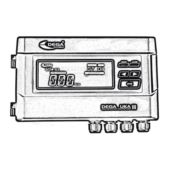
Control panel
DEGA UKA III
Reproduc�on of this manual, or any part thereof, in any form, without the prior permission of DEGA.CZ s.r.o.
is prohibited
DEGA CZ s.r.o. reserves the right to alter the specifica�ons of the hardware and so�ware described in this
manual at any �me and without prior no�ce
DEGA CZ s.r.o. bears no liability for any damage resul�ng from use of this device
Advertisement
Table of Contents

Related Manuals for DEGA UKA III


Summary of Contents for DEGA UKA III
- Page 1 Control panel DEGA UKA III Reproduc�on of this manual, or any part thereof, in any form, without the prior permission of DEGA.CZ s.r.o. is prohibited DEGA CZ s.r.o. reserves the right to alter the specifica�ons of the hardware and so�ware described in this manual at any �me and without prior no�ce...
-
Page 2: Table Of Contents
Assembly and connec�ng the wiring ..............................4 Assembly of the controller ..............................4 Connec�ng an external transmitter ............................5 Wiring installation for RS485 (Dega protocol) .........................5 Terminal resistor ..................................5 Connec�ng the temperature sensor, float sensor and lay-off bu�on of the beeper ............6 Connec�ng the visual and acous�c alarms and the emergency valve ................. -
Page 3: Technical Informa�On
Product descrip�on DEGA UKA III - the compact evalua�ng controller is designed as a stand-alone device intended for moun�ng on a wall or on distributors. It serves to evaluate the signal from up to eight connected gas sensors using RS485. The gas concentration is evaluated at four alarm levels. -
Page 4: Terminal Block
Terminal block Terminal block relay RE2 Terminal block Terminal block relay RE4 Terminal block relay relay RE3 Terminal block relay Visual alarm output Acous�c alarm Emergency valve output output Trimmer for regula�ng Power supply Power supply USB connector the supply voltage 230 VAC or 24 VDC 20-28 VDC Backup ba�ery for... -
Page 5: Connec�Ng An External Transmitter
Connecting an external transmi�er Note: Connec�on of transmi�ers with control panel only by DEGA protocol, not MODBUS protocol. It is possible to connect up to max. 16 transmitters on each controller input (BUS 0, BUS 1), depending on their electrical distance from the controller. -
Page 6: Connec�Ng The Temperature Sensor, Float Sensor And Lay-Off Bu�On Of The Beeper
Connecting the temperature sensor, float sensor and lay-off bu�on of the beeper Connecting the visual and acoustic alarms and the emergency valve Selec�ng the supply voltage and the maximum current load Supply voltage 230 VAC The highest current load of the controller is 430 mA. This current serves to power the connected transmitters and the visual and acous�c alarms, which are connected to the terminal blocks „LIGHT_SIG“... -
Page 7: Output Relay
Output relay Each relay can, by default, be configured to activate on any number and any combina�on of events: 4 gas leak alarm levels, PEL, STEL, malfunc�on of the transmitter 2 temperature levels, float, switchboard malfunc�on. A�er ac�va�on, relays can be configured for the following output func�ons: normally closed, normally open, cycling of open/close, automa�c deac�vation of outputs after a certain time or after pressing a button. -
Page 8: Panel
Panel Indica�on of proper Gas leak, alarm LEFT bu�on (move through LCD dispay opera�on of the status indica�on menus, switch between controller transmitters) RIGHT bu�on (move ENTER bu�on through menus, switch (deac�va�on of the between transmitters) acous�c alarms, selec�on of transmitter, confirm selec�on) LCD display Time... -
Page 9: Launch Of The Controller
Launch of the controller When the power supply is turned on, the en�re LCD display will light up, the internal memory will be checked and the controller will switch to the sensor hea�ng mode, with the display showing the countdown to the end of prehea�ng on the main screen and the inscrip�on “HEATING”... -
Page 10: History Menu Hist
Note.: In the case of equipping a larger quan�ty of transmi�ers, the loading of the history may take a few seconds. Informa�on menu INFO NCAL Displays the date of the next transmitter calibra�on LCAL Displays the date of the calibra�on TEMP Displays the temperature of the DEGA Tc II sensor EXIT Returns one level up in the menu... -
Page 11: Configura�On Menu Conf
For entries „LCAL“ and „NCAL“ use the arrows to switch between individual transmitters. Moving to „NCAL“displays the date and �me of the next calibra�on for the selected sensor. In addi�on, the main display shows the amount of hours remaining to the next calibration. -
Page 12: Service Menu Serv
The exact interval depends on the purity of the environment, required accuracy and the occurrence of disturbing gases in the atmosphere. The calibration interval can be changed by the DEGA Config software. Perform calibration only at certified service centers with a valid cer�ficate of competence, or the manufacturer. -
Page 13: Add-On Modules And Accessories
Intrinsic safety Zener barrier 28 V, 300 Ohm, 93 mA 10300019 Moun�ng box for Zener barriers IP 54 (30 x 22 x 12 cm) with DIN rail 10300021 DEGA Configuration&Calibra�on software Configura�on software DEGA Config with USB Cabel Attachments 1. Table of error codes Displayed on auxiliary Cause Solu�on... -
Page 14: General Warranty Terms And Conditions
• contrary to the advice provided in the instruc�on manual DEGA products that have been used in association with other than original DEGA products, including consumables and • accessories calibration of controllers, i.e.
Need help?
Do you have a question about the UKA III and is the answer not in the manual?
Questions and answers