
Related Manuals for Quectel HC06U EVB


Summary of Contents for Quectel HC06U EVB
- Page 1 HC06U EVB User Guide Bluetooth Module Series Version: 1.0 Date: 2021-08-27 Status: Released...
- Page 2 Bluetooth Module Series At Quectel, our aim is to provide timely and comprehensive services to our customers. If you require any assistance, please contact our headquarters: Quectel Wireless Solutions Co., Ltd. Building 5, Shanghai Business Park Phase III (Area B), No.1016 Tianlin Road, Minhang District, Shanghai...
- Page 3 Except as otherwise set forth herein, nothing in this document shall be construed as conferring any rights to use any trademark, trade name or name, abbreviation, or counterfeit product thereof owned by Quectel or any third party in advertising, publicity, or other aspects.
-
Page 4: Safety Information
FG50V module. Manufacturers of cellular terminals should notify users and operating personnel of the following safety precautions by incorporating them into all product manuals. Otherwise, Quectel assumes no liability for customers’ failure to comply with these precautions. -
Page 5: About The Document
Bluetooth Module Series About the Document Revision History Version Date Author Description 2021-07-11 Elinor WANG Creation of the document 2021-08-27 Elinor WANG First official release HC06U_EVB_User_Guide 4 / 20... -
Page 6: Table Of Contents
Figure Index ..............................7 Introduction ............................8 General Overview ..........................9 2.1. Top View of EVB ........................9 2.2. HC06U EVB Component Placement ..................10 Interface Application ........................12 3.1. Power Supply Interface (J13)....................12 3.2. Power Button (K2) ........................13 3.3. - Page 7 Bluetooth Module Series Table Index Table 1: Interfaces of HC06U EVB ......................11 Table 2: Terms and Abbreviations ......................20 HC06U_EVB_User_Guide 6 / 20...
- Page 8 Bluetooth Module Series Figure Index Figure 1: HC06U EVB Top View ........................9 Figure 2: HC06U EVB Component Placement ..................10 Figure 3: USB Interface and USB Status Indication .................. 12 Figure 4: Power Supply Circuit ........................13 Figure 5: Power Button ..........................13 Figure 6: Reset Button ..........................
-
Page 9: Introduction
Bluetooth Module Series Introduction HC06U EVB is an auxiliary tool for engineers to develop applications based on HC06U. It can be used to test basic functionalities of HC06U. Since the physical development board is suitable for a variety of modules, this document only explains the interfaces and test points related to the HC06U. -
Page 10: General Overview
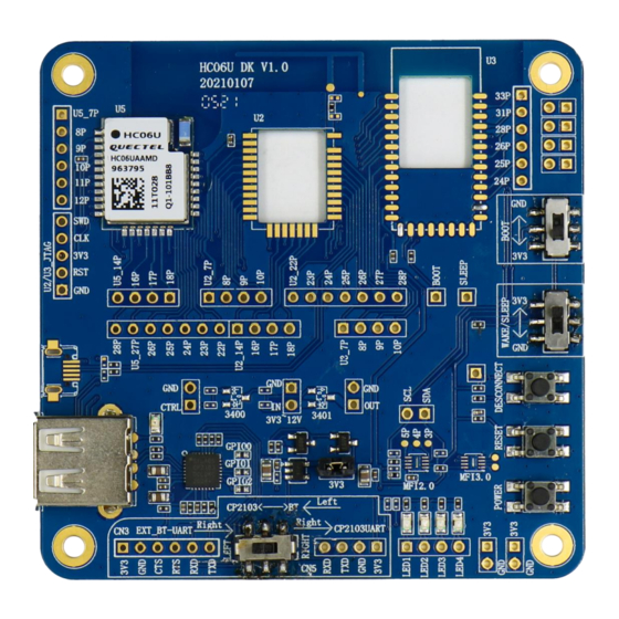
Bluetooth Module Series General Overview Quectel supplies the EVB for engineers to develop applications based on Quectel HC06U. This EVB can be used to test basic module functionalities. 2.1. Top View of EVB Figure 1: HC06U EVB Top View HC06U_EVB_User_Guide... -
Page 11: Hc06U Evb Component Placement
HC06U SPI_MOSI I2C_SCL I2C_SDA BOOT SLEEP CN10 USB_LED USB to UART Right Left 80 mm Figure 2: HC06U EVB Component Placement NOTE The component placement only shows the functions and test points related to the HC06U. HC06U_EVB_User_Guide 10 / 20... - Page 12 Bluetooth Module Series Table 1: HC06U EVB Interfaces Interface Reference Designator Description USB interface Power Supply Typical supply voltage: +5 V Power Button VCC ON/OFF control Reset HC06U reset button Wake/Sleep Sleep switch BOOT Programming mode switch Status Indication LED...
-
Page 13: Interface Application
The HC06U EVB can be powered by USB interface (J13). Figure 3: USB Interface and USB Status Indication The following figure shows the HC06U EVB power supply schematic diagram. When using the USB to supply power to the module, J4 Pin 1 and Pin 2 need to be connected. -
Page 14: Power Button (K2)
Figure 4: Power Supply Circuit 3.2. Power Button (K2) HC06U EVB includes one power button (K2), as shown in the following figure. Figure 5: Power Button When this button (K2) is pressed, power supply of the module will be disconnected. Release the button (K2) and the module will restore the power. -
Page 15: Reset Button (K1)
Bluetooth Module Series 3.3. Reset Button (K1) HC06U EVB includes one reset button (K1), as shown in the following figure. Figure 6: Reset Button The button is directly connected to HC06U reset pin. HC06U will be reset when this button (K1) is pressed. -
Page 16: Sleep Switch (Jk3)
Bluetooth Module Series 3.4. Sleep Switch (JK3) HC06U EVB includes one sleep switch (JK3), as shown in the following figure. Figure 7: Sleep Switch Slide this switch to 3V3 and then press the reset or power button to put HC06U into sleep mode. In contrast, slide this switch to GND and then press the reset or power button to put HC06U into normal mode. -
Page 17: Boot Switch (Jk2)
Bluetooth Module Series 3.5. Boot Switch (JK2) HC06U EVB includes one boot switch (JK2), as shown in the following figure. Figure 8: Boot Switch Slide this switch to GND and then press the reset or power button to put HC06U into programming mode. -
Page 18: Uart Switch (Jk1)
Bluetooth Module Series 3.6. UART Switch (JK1) HC06U EVB includes one UART switch (JK1), as shown in the following figure. Figure 9: UART Switch Slide this switch to the left side to establish communication between HC06U and the USB interface. Slide this switch to the right side to establish communication between HC06U and external MCU UART. -
Page 19: Test Points
Bluetooth Module Series 3.7. Test Points This EVB includes multiple HC06U test points, as shown in the figure below. Figure 10: Test Points The following figure shows the HC06U test point schematic diagram: Figure 11: CN6, CN10, CN11 Schematic Diagram HC06U_EVB_User_Guide 18 / 20... - Page 20 Bluetooth Module Series Figure 12: J23, J24, SLEEP, BOOT Schematic Diagram HC06U_EVB_User_Guide 19 / 20...
-
Page 21: Appendix References
Bluetooth Module Series Appendix References Table 2: Terms and Abbreviations Abbreviation Description Connector Evaluation Board Ground Light Emitting Diode Microcontroller Unit Radio Frequency UART Universal Asynchronous Receiver & Transmitter Universal Serial Bus Voltage Common Collector HC06U_EVB_User_Guide 20 / 20...
Need help?
Do you have a question about the HC06U EVB and is the answer not in the manual?
Questions and answers