Table of Contents
Advertisement
Quick Links
INSTRUCTIONS–PARTS LIST
This manual contains important
warnings and information.
READ AND KEEP FOR REFERENCE.
INSTRUCTIONS
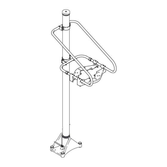
120 to 400 lb. SIZE, EXPOSED DRUM
Elevator
200 psi (1.4 MPa, 14 bar) Maximum Working Pressure
Model 204–352
GRACO INC. P.O. BOX 1441 MINNEAPOLIS, MN 55440–1441
COPYRIGHT 1996, GRACO INC.
Graco Inc. is registered to I.S. EN ISO 9001
306–568
Supersedes 4/75
First choice when
quality counts.
Rev. B
Advertisement
Table of Contents

Related Manuals for Graco 204-352


Summary of Contents for Graco 204-352
- Page 1 120 to 400 lb. SIZE, EXPOSED DRUM Elevator 200 psi (1.4 MPa, 14 bar) Maximum Working Pressure Model 204–352 GRACO INC. P.O. BOX 1441 MINNEAPOLIS, MN 55440–1441 COPYRIGHT 1996, GRACO INC. Graco Inc. is registered to I.S. EN ISO 9001...
-
Page 2: Table Of Contents
This equipment is for professional use only. Read all instruction manuals, tags, and labels before operating the equipment. Use the equipment only for its intended purpose. If you are not sure, call your Graco distributor. Do not alter or modify this equipment. -
Page 3: Installation
Installation 1. Place the unit in the desired location, making sure 4. Loosen the elevator clamps and slide the support to have adequate clearance for plumbing while the bracket down over the elevator riser tube. See unit is being raised or lowered. Overall height of Fig. -
Page 4: Operation
Operation See Fig. 2. To raise the elevator, pull out on the knob of the push-pull valve. The speed at which the elevator raises can be adjusted at the restrictor valve: Loosen the locknut, and turn the restrictor valve screw clock- restrictor push–pull wise to decrease the speed, and counterclockwise to... -
Page 5: Parts Drawing, Elevator Assembly
Parts Drawing, Elevator Assembly... -
Page 6: Parts Drawing, Support & Mounting Brackets
Parts Drawing, Support & Mounting Brackets Detail A, Push–Pull Valve Detail B, Restrictor Valve to air supply restrictor valve (see Detail B) push-pull valve (see Detail A) -
Page 7: Parts List
Parts List Ref. Ref. Part No. Description Qty. Part No. Description Qty. 204–385 ELEVATOR ASSY. (Series C) 100–181 . NUT, square; .31”–18 Includes items 2–22 100–214 . LOCKWASHER, spring; .31” 100–055 . SCREW, type “u” drive; 100–333 . SCREW, hex hd cap; .25”–20 x .50” no. -
Page 8: Mounting Hole Layout
Mounting Hole Layout 5.50” (140 mm) 8.875” (219 mm) 0.562” (14.27 mm) holes Dimensions Raised 94” (2390 mm) 23” (585 mm) Lowered 55” (1400 mm) 13” (330 mm) - Page 9 Notes...
- Page 10 Notes...
- Page 11 Manual Change Summary This manual was revised to update the format and drawings electronically.
-
Page 12: Graco Warranty
Graco distributor to the original purchaser for use. With the exception of any special, extended, or limited warranty published by Graco, Graco will, for a period of twelve months from the date of sale, repair or replace any part of the equipment determined by Graco to be defective.
Need help?
Do you have a question about the 204-352 and is the answer not in the manual?
Questions and answers