Table of Contents
Advertisement
Quick Links
Advertisement
Table of Contents

Related Manuals for Hantek DDS-3005 USB


Summary of Contents for Hantek DDS-3005 USB
- Page 1 User’s Guide DDS-3005 USB Operation Manual...
-
Page 2: Table Of Contents
Chapter 3 Software Operations ................. 6 3.1 Installing the Hardware................... 6 3.2 Installing the Software ..................9 3.3 Run the DDS-3005 USB................10 3.4 Choose the Wave Forms................10 3.5 Waveform Parameter Setup ................. 10 3.6 Counter/ Frequency Measurement............... 11 3.7 Waveform Output Control................ -
Page 3: Chapter 1 Introduction
Gauss Noise, Trapezia, Exponent, AM and FM. The parameters, such as amplitude, frequency and offset, are also settable. The data format of DDS-3005 USB is completely compatible with that of Tektronix; it can directly read the waveform data files produced by the Tektronix oscilloscope or Tektronix waveform editor software and redisplay the waveform. - Page 4 Output Current 50mA Vpeak=100mA 5MHz, 1MHz, 100KHz, 10KHz, 1KHz Low Pass Filter Programmable Control Harmonic Wave -65dBc(1KHz), -53dBc(10KHz) distortion Frequency Counter Channel 1 Range DC~25MHz Input Amplitude 400mVpp~25Vpp Coupling Mode AC, DC Programmable ±Time Base Error ±1 Count Accuracy Input Impedance >...
-
Page 5: Chapter 2 Installation
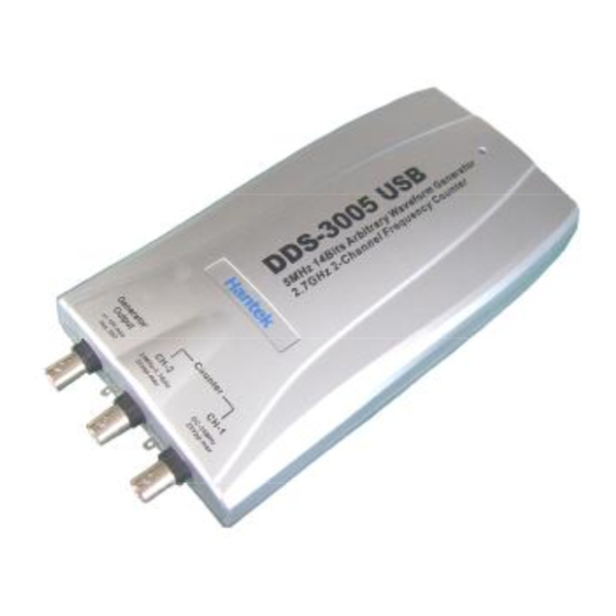
Chapter 2 Installation 2.1 System requirements l Minimum System Requirements Operating System Windows 98/2000/XP Memory 128Mbyte Graphic Card Microsoft DirectX supported Screen resolution: 1024x768 Color depth: 16bit l Recommended System Requirements Operating System Windows 98/2000/XP Memory 256Mbyte Graphic Card Microsoft DirectX supported Screen resolution: 1024x768 Color depth: 16bit 2.2 Shape and Terminal Illustration... - Page 6 DDS-3005 USB Shape...
- Page 7 PIN1 Bit7 PIN2 Bit6 PIN3 Bit5 PIN4 Bit4 PIN5 Bit3 PIN6 Bit2 PIN7 Bit1 PIN8 Bit0 PIN9 Synchronized Signal Output PIN10 Digital Ground Digital Output Port Definition PIN1 Bit7 PIN2 Bit6 PIN3 Bit5 PIN4 Bit4 PIN5 Bit3 PIN6 Bit2 PIN7 Bit1 PIN8 Bit0...
-
Page 8: Chapter 3 Software Operations
Chapter 3 Software Operations 3.1 Installing the Hardware Connect the USB instrument to the USB port through the USB cable, the PC prompts that new USB device is found. The PC will automatically find the new USB device and choose the nominated directory to install the driver. - Page 9 Click Continue to finish the installation. " "...
- Page 10 The system will notify that the new USB device can work normally now. After the successfully installation, in the Device Manager, you can see the DDS-3005 USB device.
-
Page 11: Installing The Software
3.2 Installing the Software The setup software of DDS-3005 USB is in the CD, run the Setup.exe to install the software. -
Page 12: Run The Dds-3005 Usb
3.3 Run the DDS-3005 USB Click Start Program DDS-3005 USB DDS-3005 USB to go into the main " " " " " " " " window, shown as below: 3.4 Choose the Wave Forms Press down any button of certain waveform to switch to the output of such kind of waveform. -
Page 13: Counter/ Frequency Measurement
Example modulation Signal " " Set the parameters in the dialog box. 3.6 Counter/ Frequency Measurement To measure by the buttons shown as below: Including "High Frequency/ Low Frequency”, "Coupling Mode" "Frequency Measure/ Counter" and the function’s "On/Off". 3.7 Waveform Output Control By the following buttons to control the output dot numbers, trigger mode, output amplitude, and limit frequency of the wave filter. -
Page 14: Edition Of Arbitrary Waveform
" " " window to edit each dot, or use the mouse the draw the waveform. 3.9 Waveform Data Files The data format of DDS-3005 USB is .CSV . Its format is compatible with the " " CSV file produced by the Tektronix ARBExpress software. User can edit or set up the required CSV waveform and also use Excel to open and edit the CSV wave files. - Page 15 strong electrical field and static may cause the abnormal working or even damage to the instrument.
Need help?
Do you have a question about the DDS-3005 USB and is the answer not in the manual?
Questions and answers