Table of Contents
Advertisement
Quick Links
Gas Analysis
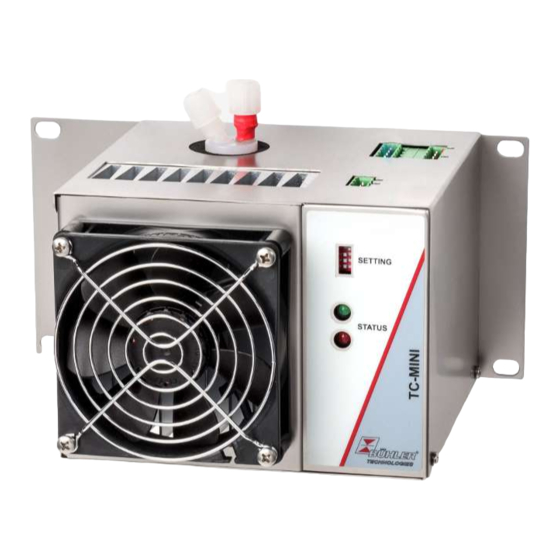
Sample gas cooler
TC-MINI
Installation and Operation Instructions
Original instructions
BE440015
Bühler Technologies GmbH, Harkortstr. 29, D-40880 Ratingen
04/2023
Tel. +49 (0) 21 02 / 49 89-0, Fax: +49 (0) 21 02 / 49 89-20
E-Mail: analyse@buehler-technologies.com
Internet: www.buehler-technologies.com
Advertisement
Table of Contents

Related Manuals for Buhler TC-MINI


Summary of Contents for Buhler TC-MINI
- Page 1 Gas Analysis Sample gas cooler TC-MINI Installation and Operation Instructions Original instructions BE440015 Bühler Technologies GmbH, Harkortstr. 29, D-40880 Ratingen 04/2023 Tel. +49 (0) 21 02 / 49 89-0, Fax: +49 (0) 21 02 / 49 89-20 E-Mail: analyse@buehler-technologies.com Internet: www.buehler-technologies.com...
- Page 2 Bühler Technologies GmbH, Harkortstr. 29, D-40880 Ratingen Tel. +49 (0) 21 02 / 49 89-0, Fax: +49 (0) 21 02 / 49 89-20 Internet: www.buehler-technologies.com E-Mail: analyse@buehler-technologies.com Read this instruction carefully prior to installation and/or use. Pay at- tention particularly to all advises and safety instructions to prevent in- juries.
-
Page 3: Table Of Contents
TC-MINI Contents Introduction ............................................. 2 Intended use ......................................... 2 Types............................................ 2 Scope of delivery ........................................ 2 Ordering instructions...................................... 2 Safety instructions ......................................... 3 Important advice ......................................... 3 General hazard warnings .................................... 4 Transport and storage ........................................ 5 4 Installation and connection ...................................... 6 Installation site requirements.................................. 6... -
Page 4: Introduction
4496 1 X 0 4 X X X 0 0 X X X 0 0 0 0 Product Characteristics Gas cooler models (with 1 heat exchanger) TC-MINI 6111: moderate ambient temperature 40 °C TC-MINI 6112: higher ambient temperature 50 °C Certifications Standard applications – CE... -
Page 5: Safety Instructions
TC-MINI 2 Safety instructions 2.1 Important advice Operation of the device is only permitted if: – the product is used under the conditions described in the installation- and operation instruction, the intended application according to the type plate and the intended use. In case of unauthorized modifications done by the user Bühler Technolo- gies GmbH can not be held responsible for any damage, –... -
Page 6: General Hazard Warnings
TC-MINI 2.2 General hazard warnings The equipment must be installed by a professional familiar with the safety requirements and risks. Be sure to observe the safety regulations and generally applicable rules of technology relevant for the installation site. Prevent malfunctions and avoid personal injuries and property damage. -
Page 7: Transport And Storage
TC-MINI 3 Transport and storage Only transport the product inside the original packaging or a suitable alternative. The equipment must be protected from moisture and heat when not in use. It must be stored in a covered, dry and dust-free room at a temperature of -20 °C to 60 °C (-4 °F to 140 °F). -
Page 8: Installation And Connection
TC-MINI 4 Installation and connection 4.1 Installation site requirements The unit is only intended for wall-mounted use in enclosed areas. Adequate protection from the weather must be provided when used outdoors. Install the unit leaving enough room below the cooler to discharge the condensate. Leave room above for the gas supply. -
Page 9: Connecting The Filter Gas Connections (Optional)
TC-MINI 4.2.1 Connecting the filter gas connections (optional) The connection G1/4 or NPT 1/4” (filter head marked NPT) for the gas outlet must be carefully and properly connected using a suitable screw connection. When ordering the cooler with the option filter without Moisture detector, a bypass may be connected to the filter head. - Page 10 TC-MINI X2.1 X2.5 X2.10 X2.6 X1.1 DIP Switch / Settings LED green LED red Inputs/outputs Terminal Function Description Moisture detector X1.1 FF.1 (white) Moisture detector X1.2 FF.2 (brown) X1.3 Shield for moisture detector inlet Status X2.1 Status NC (Alarm) Alarm/Status X2.2...
-
Page 11: Settings
As seen in the following graphics using the TC-MINI 6111 as an example, a difference of 15 °C from the ambient temperature means the focus is on drying the sample gas. The stability of the dew point then takes a backseat to the high performance which can be achieved. - Page 12 TC-MINI DIP switch The unit is configured using four DIP switches at the front of the cooler. ON switch OFF switch Switch, the following numbering of the SWs corresponds with the numbering on the DIP switch. SW1 / SW2 Gas output dew point 3 °C...
-
Page 13: Operation And Control
TC-MINI 5 Operation and control NOTICE The device must not be operated beyond its specifications. After switching on the supply voltage the cooler starts to cool the cooling block. When switched off the contact between X2.1 and X2.2 is closed. -
Page 14: Modbus Communication
TC-MINI 5.4 Modbus Communication Communication via Modbus RTU is always imitated by the master (request). The slave (typically) responds to the request with a response. A Modbus RTU frame for a request/response always has the following structure: Address field (A) -
Page 15: Modbus Register
5.5 Modbus Register Description Address Access Data type Default Selection Resolution Unit Block temperature measurement 2000 Float °C Block temperature status 2002 Uint32 Bit 0 : = error Bit 1..15 := reserved Bit 16 := sensor not calibrated Bit 17 := initialization / measurement in- valid Bit 18 := stabilization phase Bit 19 := load limit reached... - Page 16 Description Address Access Data type Default Selection Resolution Unit 4 := 38400 5 := 57600 6 := 115200 Modbus Parity selection 3, 16 9010 Uint16 0 := none 1 := odd 2 := even Modbus Device address selection 3, 16 9011 Uint16 TEST 9990...
- Page 17 Description Address Access Data type Default Selection Resolution Unit Bit 5 := Bit 6 := Bit 7 := Condition code register 4 10004 Uint16 Bit 0 := Bit 1 := Bit 2 := Bit 3 := Bit 4 := Bit 5 := Bit 6 := Bit 7 := Error register 1...
- Page 18 Description Address Access Data type Default Selection Resolution Unit Bit 5 := Bit 6 := Bit 7 := Error register 6 - PT100.2 10010 Uint16 Bit 0 := general error Bit 1 := short-circuit / temperature low Bit 2 := cable break / temperature high Bit 3 := measurement fluctuation Bit 4 := Bit 5 :=...
-
Page 19: Maintenance
TC-MINI 6 Maintenance The basic version of the cooler requires no special maintenance. However, it may have different options depending on the configuration ordered. In this case the following routine maintenance is required: Filter option: Check filter element (see chapter Replacing the filter element (option) [>... -
Page 20: Service And Repair
TC-MINI 7 Service and repair This chapter contains information on troubleshooting and correction should an error occur during operation. Repairs to the unit must be performed by Bühler authorised personnel. Please contact our Service Department with any questions: Tel.: +49-(0)2102-498955 or your agent For further information about our services and customised maintenance visit http://www.buehler-technologies.com/service. -
Page 21: Troubleshooting
TC-MINI 7.1 Troubleshooting Problem/malfunction Possible cause Action No LED lights up – Mains voltage interrupted – Connect to mains; check the plug is cor- rectly inserted – Fuse defective – Check fuse and replace if necessary – LED defective – Send in cooler –... -
Page 22: Safety Instructions
TC-MINI 7.2 Safety instructions – The device must be operated within its specifications. – All repairs must be carried out by Bühler authorised personnel only. – Only perform modifications, servicing or mounting described in this manual. – Only use original spare parts. -
Page 23: Replacing The Filter Element (Option)
TC-MINI 7.5 Replacing the filter element (option) CAUTION Gas leakage The filter should not be dismantled under pressure. Don’t use damaged parts again. – Close the gas supply. – Switch off and unplug the device. – Pull the bracket, holding on to the filter glass. -
Page 24: Consumables And Accessories
TC-MINI 7.7.1 Consumables and accessories Item no. Description 9112000039 24 V top-hat rail power supply 9112000040 24 V top-hat rail power supply for using the 24 V output 4510008 Automatic condensate drain AK 5.2 4510028 Automatic condensate drain AK 5.5... -
Page 25: Disposal
TC-MINI 8 Disposal The heat exchanger is charged with glycol-based coolant. The applicable national laws must be observed when disposing of the products. Disposal must not result in a danger to health and environment. The crossed out wheelie bin symbol on Bühler Technologies GmbH electrical and electronic products indicates special disposal notices within the European Union (EU). -
Page 26: Appendices
TC-MINI 9 Appendices 9.1 Gas cooler technical data Gas Cooler Technical Data Ready for operation after max. 10 minutes Ambient temperature 5 °C to 55 °C Gas outlet dew temperature, preset 5 °C IP rating IP 20 Housing Stainless steel, brushed Packaging dimensions approx. -
Page 27: Dimensions (Mm)
TC-MINI 9.3 Dimensions (mm) Sample gas IN/OUT Condensate approx. Optional filter 9.4 Performance data A selected outlet dew point of 10 or 15 °C shifts the curves 5 or 10 °C to the right. The MTV and MTG limits apply to a normal operating point of τ... -
Page 28: Heat Exchanger
TC-MINI 9.5 Heat exchanger 9.5.1 Heat exchanger description The energy content of the sample gas and the required cooling capacity of the gas cooler is determined by three parameters: gas temperature ϑ , dew point τ (moisture content) and volume flow v. The outlet dew point rises with increasing energy content of the gas. -
Page 29: Attached Documents
TC-MINI 10 Attached documents – Declaration of conformity: KX 440005 – RMA - Decontamination Statement BE440015 ◦ 04/2023 Bühler Technologies GmbH... - Page 32 RMA-Formular und Erklärung über Dekontaminierung RMA-Form and explanation for decontamination RMA-Nr./ RMA-No. Die RMA-Nr. bekommen Sie von Ihrem Ansprechpartner im Vertrieb oder Service. Bei Rücksendung eines Altgeräts zur Entsorgung tragen Sie bitte in das Feld der RMA-Nr. "WEEE" ein./ You may obtain the RMA number from your sales or ser- vice representative.
- Page 33 Dekontaminierungserklärung DE000011 Bühler Technologies GmbH, Harkortstr. 29, D-40880 Ratingen 12/2022 Tel. +49 (0) 21 02 / 49 89-0, Fax: +49 (0) 21 02 / 49 89-20 E-Mail: service@buehler-technologies.com Internet: www.buehler-technologies.com...
Need help?
Do you have a question about the TC-MINI and is the answer not in the manual?
Questions and answers