Table of Contents
Advertisement
Quick Links
Fluidcontrol
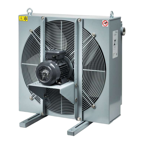
Oil/air cooler
BLK
Installation and Operation Instructions
Original instructions
BE350025
Bühler Technologies GmbH, Harkortstr. 29, D-40880 Ratingen
03/2019
Tel. +49 (0) 21 02 / 49 89-0, Fax: +49 (0) 21 02 / 49 89-20
E-Mail: fluidcontrol@buehler-technologies.com
Internet: www.buehler-technologies.com
Advertisement
Table of Contents

Related Manuals for Buhler BLK Series


Summary of Contents for Buhler BLK Series
- Page 1 Fluidcontrol Oil/air cooler Installation and Operation Instructions Original instructions BE350025 Bühler Technologies GmbH, Harkortstr. 29, D-40880 Ratingen 03/2019 Tel. +49 (0) 21 02 / 49 89-0, Fax: +49 (0) 21 02 / 49 89-20 E-Mail: fluidcontrol@buehler-technologies.com Internet: www.buehler-technologies.com...
- Page 2 Bühler Technologies GmbH, Harkortstr. 29, D-40880 Ratingen Tel. +49 (0) 21 02 / 49 89-0, Fax: +49 (0) 21 02 / 49 89-20 Internet: www.buehler-technologies.com E-Mail: fluidcontrol@buehler-technologies.com Read this instruction carefully prior to installation and/or use. Pay at- tention particularly to all advises and safety instructions to prevent in- juries.
-
Page 3: Table Of Contents
Contents Introduction............................................. 2 Intended use ......................................... 2 Model key.......................................... 2 Scope of delivery ........................................ 2 Safety instructions......................................... 3 Important advice ......................................... 3 General hazard warnings .................................... 3 Transport and storage ........................................ 5 4 Installation and connection ...................................... 6 Requirements to the installation site................................ 6 Installing the unit........................................ 6 4.2.1 Installing swivel nuts in the fitting body ............................. -
Page 4: Introduction
1 Introduction 1.1 Intended use BLK oil/air coolers are suited for the cooling of oils in hydraulic and lubrication systems. Their scope is given by their specifica- tions. The use in other applications is not permitted without confirmation by Bühler Technologies GmbH. 1.2 Model key BLK 4.6- IBx - T50 Number of motor contacts... -
Page 5: Safety Instructions
2 Safety instructions 2.1 Important advice Operation of the device is only valid if: – the product is used under the conditions described in the installation- and operation instruction, the intended application according to the type plate and the intended use. In case of unauthorized modifications done by the user Bühler Technolo- gies GmbH can not be held responsible for any damage, –... - Page 6 The operator of the system must ensure: – Safety notices and operating instructions are available and observed, – The respective national accident prevention regulations are observed, – The permissible data and operational conditions are maintained, – Safety guards are used and mandatory maintenance is performed, –...
-
Page 7: Transport And Storage
3 Transport and storage The product should only be transported inside the original packaging or a suitable alternative. Ensure secure fastening and mooring. Units with air coolers have M10 eye bolts at the top of cooler housing for transport. Please note, due to the variety of versions the mounting bracket is not located at the exact centre of gravity and the cooler may swing when hoisted. -
Page 8: Installation And Connection
4 Installation and connection 4.1 Requirements to the installation site Aggregate The aggregate must be set up to allow for unobstructed air flow and adequate room for maintenance/repairs. When installed outdoors, be sure to consider the motor protection rating (standard: IP 55) and ensure adequate protection from the weather. Air cooler The aggregate must be set up to allow for unobstructed air flow and adequate room for maintenance/repairs. -
Page 9: Hydraulic Connection
4.3 Hydraulic connection Carry out the hydraulic connection as described in the attached data. Connect the lines stress and vibration free, so typically us- ing hoses. Be sure to use suitable lines (with regard to pressure, fluid resistance, environmental influences, fire) when connecting to the hydraulic-, lubrication circuit. -
Page 10: Electrical Connections Blk 1-Phase
4.4.1 Electrical connections BLK 1-phase U1 blue Z brown U2 black PE green-yellow 4.4.2 Electrical connection temperature switch TSA The temperature switch TSA is installed in a cooling circuit with an oil/air cooler BLK as a typical application. Through reaching the switching temperature the fan-motor is switched-on and the oil will be cooled. - Page 11 Example wiring with temperature switch F1 Fuse K1 Relay F2 Fuse K2 Circuit breaker F3 Fuse S1 Protecting device H1 Mains switch S2 Protecting device Relay, circuit breaker and protecting devices are not part of the delivery. BE350025 ◦ 03/2019 Bühler Technologies GmbH...
-
Page 12: Operation And Control
5 Operation and control WARNING Danger due to rotating fan Injuries to the hand may occur. Do not reach into the safety guard! NOTICE The device must not be operated beyond its specifications. NOTICE Abrupt flow variation can lead to pressure peaks that may damage the cooler matrix. Make sure that the specifications are not exceeded in this case! 5.1 Before starting –... -
Page 13: Maintenance
6 Maintenance During maintenance, remember: – The equipment must be maintained by a professional familiar with the safety requirements and risks. – Only perform maintenance work described in these operating and installation instructions. – When performing maintenance of any type, observe the respective safety and operation regulations. DANGER Electrical voltage Electrocution hazard. -
Page 14: Cleaning And Disassembly Of The Cooler Matrix
Condensate drain holes at motors from manufacturer WEG If the motor is used in surrounding with high humidity this could lead, depending on the ambient temperature, to formation of condensate inside the motor housing. Specially at longer nonoperation period. The motors of WEG have a condensate drain plug which can be used for draining off. -
Page 15: Cleaning The Fan Case
6.3 Cleaning the fan case Due to the design, dust and dirt will not deposit in a large amount inside the fan case. Nevertheless, any deposits of dirt should be blown out each time the cooler is cleaned. 6.4 Replacing fan parts –... -
Page 16: Service And Repair
7 Service and repair This chapter contains information on troubleshooting and correction should an error occur during operation. Repairs to the unit must be performed by Bühler authorised personnel. Please contact our Service Department with any questions: Tel.: +49-(0)2102-498955 or your agent If the equipment is not functioning properly after correcting any malfunctions and switching on the power, it must be inspected by the manufacturer. -
Page 17: Disposal
8 Disposal Dispose of the parts in such a way that does not present a danger to other people’s heath or to the environment. Observe the legal requirements in the country of use for the disposal of electrical components and oils and coolants. BE350025 ◦... -
Page 18: Appendices
9 Appendices 9.1 Technical data Technical Data Materials / surface protection Cooling battery: Aluminium, painted ventilation box, safety guard and motor brackets: plastic-coated steel Colour: RAL 7001 / Motor: RAL 7024/7030 Operating fluids: Mineral oils per DIN 51524 oil-/water emulsions HFA and HFB per CETOP RP 77 H Water glycol HFC per CETOP RF 77 H Phosphoric ester HFD-R per CETOP RP 77 H Operating pressure... -
Page 19: Basic Data (At 50 Hz Frequency)
9.1.1 Basic data (at 50 Hz frequency) Item no. Cooler type Motor power Weight Capacity Noise level Number of poles (kg) db(A)* Rated current at 400 V 3501200 BLK 1.2 0,05 kW / 2 / 0,24 A (230 V) 3502200 BLK 2.2 0,55 kW / 2 / 1,4 A 3502400... -
Page 20: Performance Curves Frame Size 1-6
9.1.2 Performance curves frame size 1-6 9.1.3 Performance curves frame size 7-10 Bühler Technologies GmbH BE350025 ◦ 03/2019... -
Page 21: Dimensions
9.2 Dimensions on some models the motors are mounted with a bracket on BLK 9 and 10 = 150 mm Connection fitting on BLK 9 and 10 only Model BLK 1.2 62,5 2x G1/2 BLK 2.2 83,5 2x G1 BLK 2.4 83,5 2x G1 BLK 3.2... -
Page 22: Functional Diagram
9.3 Functional diagram Standard version BLK 2 Standard version BLK 1, 3 to BLK 10 Direction of flow left to right or vice versa. Direction of flow top left to bottom right or the exact opposite. The oil outlet is always on the opposite side. The second con- nection must be closed. -
Page 23: Installation Torques And Clamping Range For Cable Fitting
9.4 Installation torques and clamping range for cable fitting Strain relief clamping Installation torque (Nm) Size range (mm) M12x1,5 M16x1,5 5-9,5 M20x1,5 8-13 M25x1,5 11-17 M32x1,5 15-21 M40x1,5 19-28 M50x1,5 27-35 M63x1,5 32-42 9.5 Screw torques Thread Torque (Nm) 9.6 Hose torques Connections/mounts Torque (Nm) Hose connections DN20... -
Page 24: Table Of Operational Viscosity For Vg Oil
9.7.2 Table of operational viscosity for VG oil 10 °C 20 °C 30 °C 40 °C 50 °C 60 °C 70 °C 80 °C 90 °C VG 46 264,45 131,96 73,58 46,00 29,13 20,04 14,43 10,78 8,32 VG 68 444,77 210,85 112,61 68,00... - Page 25 BFP 30 28 l/min – DN 32 VG 46 VG 68 VG 120 VG 160 VG 220 VG 320 VG 460 VG 680 10 °C 0.04 0.07 0.15 0.22 0.33 0.54 0.88 1.48 20 °C 0.02 0.03 0.06 0.09 0.13 0.21 0.33 0.52...
-
Page 26: Attached Documents
10 Attached documents – Declaration of conformity KX350001 – RMA - Decontamination Statement Bühler Technologies GmbH BE350025 ◦ 03/2019...
Need help?
Do you have a question about the BLK Series and is the answer not in the manual?
Questions and answers