Advertisement
Quick Links
04062009
1. Technical description.
1.1.
General description.
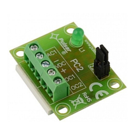
PC2 (AWZ 518) time module is used for control of AC supply state of object alarm systems (monitoring
transmitters, alarm centrals, DC power supply unit etc.). The module makes it possible to pass information about decay
of AC supply with the set delay time of T (3s/63s/17m37s/4h45m, +/-2%) and information about recovery of AC supply.
Recovery of AC voltage (transient) during counting of T delay time triggers counting reset (i.e. stop and return to the
normal state). The module has an AC1 input that shall be connected to a secondary wiring terminal of a transformer
supplying the device (the module shall be supplied by 12V/DC, i.e. the device to which the controlled transformer
terminal is connected). PC2 has two OC outputs (OC1, OC2) and a LED (L1) indicating the state of the device. Two Z1
and Z2 jumpers are used for configuration of the signalling delay time of AC supply decay.
1.2. The connection diagram of the module (fig.1).
Edition: 1st from the 23rd May of 2008
Supercedes edition: ----------
Fig.1. The connection diagram of the PC2 module (example).
PC2
AWZ 518
v.1.0
Time module for AC control
1
EN
Advertisement

Related Manuals for Pulsar PC2 AWZ 518


Summary of Contents for Pulsar PC2 AWZ 518
- Page 1 AWZ 518 v.1.0 Time module for AC control 04062009 Edition: 1st from the 23rd May of 2008 Supercedes edition: ---------- 1. Technical description. 1.1. General description. PC2 (AWZ 518) time module is used for control of AC supply state of object alarm systems (monitoring transmitters, alarm centrals, DC power supply unit etc.).
- Page 2 1.3. Description of the elements and connectors of the PC2 module and their functions (tab.1, tab.2, fig.2). Table 1. Description of the element [fig.2 Green LED L1 – signalling of the module state lights continuously: AC voltage at AC1 terminal, state H, •...
- Page 3 1.3. Technical parameters: - electrical parameters (tab.3) - mechanical parameters (tab.4) Table 3. Supply voltage 10V÷15V/DC (-5%/+5%) Current consumption 5mA max. Ranges of T delay settings 3s/65s/17m40s/4h45m (-2%/+2%) AC1 input 0V-30V AC (-2%/+2%) state L ( ‘0’ logical)= 0V-1,5V AC state H (‘1’...
- Page 4 Pulsar K.Bogusz Sp.j. Siedlec 150, 32-744 Łapczyca, Poland Tel. (+48) 14-610-19-40, Fax. (+48) 14-610-19-50 e-mail: biuro@pulsar.pl, sales@pulsar.pl http:// www.pulsar.pl WEEE MARK The waste electrical and electronic equipment, do not mix with general household waste. There are separate collection systems for waste electrical and electronic equipment in accordance with legislation under the WEEE Directive and is effective only with EU.
Need help?
Do you have a question about the PC2 AWZ 518 and is the answer not in the manual?
Questions and answers