
Related Manuals for Pulsar MSRD 1024


Summary of Contents for Pulsar MSRD 1024
- Page 1 MSRD 1024 v.1.0 MSRD 27,6V/1A Buffer switch mode power supply module Edition: 1st (14th Mar 2012) Supercedes:---------------...
- Page 2 MSRD1024 Features: • • Uninterrupted supply of 27,6VDC/1A START facility for manual battery connection • • STOP button for battery disconnection during supply voltage: external transformer required battery-assisted operation 27-30VAC (AWT5172430, AWT049) • • FAC technical output indicating AC power high efficiency 85% •...
- Page 3 MSRD1024 1.2. Block diagram. Fig.1. Block diagram of the PSU module 1.3. Description of components and connectors (Fig.2, tab.1). Table 1. Description of components and connectors (see Fig. 1). Element no. Description AC, AUX, LB, F LED indication for PSU module operating status FAC - technical output for no AC network - relay type Caution! In Fig.2.
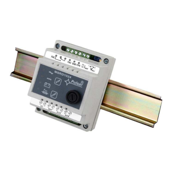
- Page 4 MSRD1024 Fig. 2. The view of the PSU module 1.4. Specifications: - electrical specifications (tab.2) - mechanical specifications (tab.3) - operating specifications (tab.4) Electrical specifications (tab. 2). Supply voltage 27V÷30V/AC (e.g.AWT5172430, AWT049) Current consumption 1,6 A max. Power frequency...
- Page 5 MSRD1024 -R – relay type, 1A@ 30Vdc/50Vac max. Technical outputs: CAUTION! In Fig.2. the set of contacts indicates potential- - FAC; output indicating failure of AC power free status which corresponds to AC power outage (AC supply power failure) - OC type, 50mA max., normal status: L (0V) level, failure:...
- Page 6 MSRD1024 ought to be followed- accordingly to the application. The module requires 27-30V AC power supply with galvanic separation (transformer insulation). The minimum power of the transformer: 40VA. 2.2 Installation procedure 1. Install an enclosure, a distribution board or a cabinet and lead the cables through the cable ducts.
- Page 7 MSRD1024 4. Operation and use. 4.1 Overload or short circuit of the PSU module output The AUX output of the PSU module is equipped with the PTC polymer fuse assisted protection. If the load of the PSU module exceeds 1A (load 110% ÷ 150% @25ºC of the PSU module power), the output voltage is automatically cut off and indicated by the green diode going out.
- Page 8 GENERAL WARRANTY CONDITIONS 1. Pulsar K. Bogusz Sp.j. (the manufacturer) grants a two-year warranty for the equipment, starting from the initial product date of purchase placed on the receipt. 2. If a purchase proof is missing, a three-year warranty period is counted from the device’s production date.
Need help?
Do you have a question about the MSRD 1024 and is the answer not in the manual?
Questions and answers