ENGO CONTROLS E901RF, E901 - Wireless/Hardwired Programmable Thermostat Quick Guide
- Full manual (38 pages)
Advertisement
- 1 Introduction
- 2 Overview
- 3 Product Compliance
- 4 Safety Information
- 5 Installation
- 6 Wall mounting
- 7 Connection description for wired thermostat E901
- 8 E901RX receiver from the wireless kit
- 9 Connection description for wireless thermostat E901RF
- 10 LCD icon description
- 11 Button description
- 12 Setting Time / Setting Date
- 13 Manual mode - temperature settings
- 14 Setting the comfort temperature
- 15 Setting the economic temperature
- 16 AUTO mode - work according to the schedule
- 17 Selection of factory (0-3) programs
- 18 Choosing and programming (4-9) user programs
- 19 The second type of schedule and the programming method
- 20 E901RF pairing process with the receiver
- 21 Installer settings
- 22 Installer parameters
- 23 Technical specification
- 24 Documents / Resources
Introduction
E901 & E901RF is a weekly, surface-mounted electronic room thermostat intended for home use. It has been designed for control of heating devices (e.g. gas, oil boilers, heat pumps) or cooling devices. It has the function of creating your own schedules. Thanks to the built-in algorithms, it offers much better temperature control accuracy than traditional mechanical thermostats. Please read these instructions carefully before using the device for the first time. The thermostat should use AA, 1.5V alkaline batteries. Put the batteries in the battery compartment located under the flap. Rechargeable batteries are not allowed.
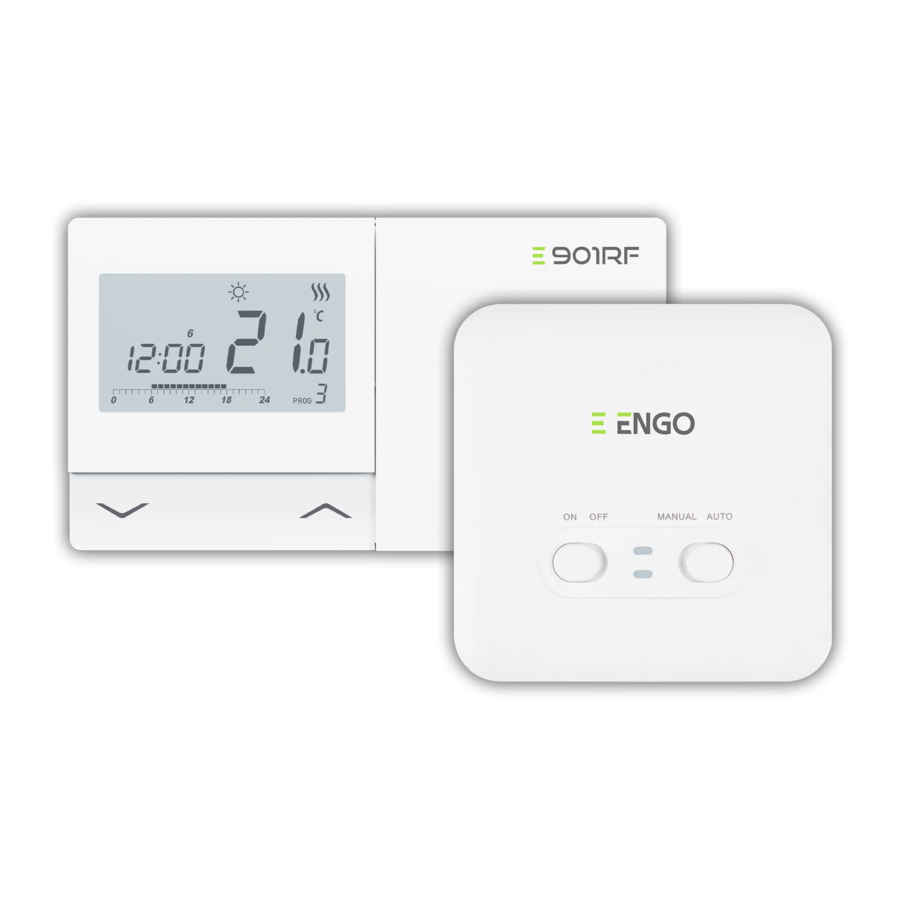
Overview
E901RF | Wireless Programmable Thermostat

E901 | Hardwired Programmable Thermostat

Product Compliance
This product complies with the following EU Directives: E901: 2014/30/EU, 2014/35/EU, 2011/65/EU
E901RF: 2014/53/EU, 2011/65/EU
 868.0 MHz - 868.6 MHz; <13dBm
 Please note!
This document is a quick guide for installing and operating the product and indicates its most important features and functions.
Safety Information
Use in accordance with national and EU regulations. Use the device only as intended, keeping it in a dry condition. The product is for indoor use only. Installation must be carried out by a qualified person in accordance with national and EU regulations.
Installation
Installation must be performed by a qualified person with appropriate electrical qualifications, in accordance with the standards and regulations in force in a given country and in the EU. The manufacturer is not responsible for non-compliance with the instructions.

For the entire installation, there may be additional protection requirements, which the installer is responsible for.

The purpose of this symbol is to indicate that this device should not be discarded in household waste. For the protection of the environment, human health and natural resources, disposal should only take place at an appropriate recycling collection facility for WEEE directive products. For more information on disposal and recycling of this product please contact local municipal authorities, disposal services or the original point of purchase.
On sale, exchange or disposal of a device we recommend you reset or delete any device settings. Internet connected devices should be removed from any registered online accounts, Mobile or Web Apps, or the online account should be closed to ensure device data is no longer linked or associated with your personal details. It is the consumer's responsibility to remove a device, close an account, or notify us of any change in ownership to ensure any association or linkage to personal accounts is removed or updated.
Wall mounting
- Remove the thermostat cover as shown in the picture. If there are batteries inside, remove them.

- Use a screwdriver to push the plastic tabs in as shown in the figure until you feel resistance, and tilt the front part of the housing.

- Separate the front part from the back part in the direction shown above.

- Then fix the back cover to the wall using the supplied mounting screws and the holes provided (see bigger arrows). Connect the wires to the COM / NO connector (see smaller arrows).

- Using the hinges from left, fold the back and front covers by moving as shown in the picture above until they click into place.


Connection description for wired thermostat E901

E901RX receiver from the wireless kit
Receiver's switches description:

| LEFT SWITCH | |
| 1. | ON - Manual mode
|
| 2. | OFF - Manual mode
|
| RIGHT SWITCH | |
| 3. | MANUAL - Receiver works in manual mode (according to the left switch) |
| 4. | AUTO - Receiver works in AUTO mode (according to the thermostat's command) |
LED indications in the receiver

The status of the receiver is indicated by two LEDs. These are LEDs with the following colors:
- - green (upper one),
- - orange (lower one).
A detailed explanation of the meaning of the LEDs can be found in the table below:
| DESCRIPTION | |
| The green LED lights up | The receiver is connected to the 230V power supply. The receiver can be controlled by thermostat if it is in automatic mode when the right switch is in the AUTO position. The receiver can be started manually when the right switch is in the MANUAL position. |
| The green LED flashes | The receiver is in the pairing mode and is looking for a signal from the thermostat (then you must activate the "SYNC" parameter in the thermostat). |
| The green LED is off | The receiver is disconnected from the 230V power supply or the left switch is in the OFF position. |
| The orange LED lights up | In automatic mode, the receiver received a heating / cooling signal from the thermostat. The receiver was started in manual mode (left ON switch, right MANUAL switch) |
| The orange LED flashes | The receiver was paired but lost communication with the thermostat due to out of range or low battery in the thermostat. The receiver starts flashing after 40 minutes of time when it does not receive a signal from the thermostat. |
| The orange LED is off | The receiver does not send a heating / cooling signal. |
Connection description for wireless thermostat E901RF

LCD icon description
![]()
- Program timeline indicator
- AM/PM
- Clock
- Day of the week indicator
- Settings icon
- Key lock function
- Send a signal (pairing)
- Holiday Mode
- Low battery indicator
- Antifrost Mode
- Comfort Mode
- Economic Mode
- Cooling mode - ON
- Heating mode - OFF
- Temperature unit
- Room / setpoint temperature
- Temporary override
- Program number
Button description
| Button | Function |
 | Change the parameter value down |
 | Change the parameter value up |
 | Set the day of the week |
 | Set the hour |
 | Set the minutes |
 | Comfort temperature |
 | Economic temperature / Holiday mode |
 | AUTO mode / Back button |
 | Programming / Program selection |
 | Confirm function |
 | Factory Reset |
Setting Time / Setting Date

![]() - Press D button to set the day.
- Press D button to set the day.![]() - Press H button to set the hour.
- Press H button to set the hour.![]() - Press M button to set the minutes.
- Press M button to set the minutes.
 -
-  -
-  -
- Manual mode - temperature settings
There are several temperature levels at our disposal. Only one temperature level is realized 24 hours a day in manual mode. You can set a different temperature for each level.
 - Comfort Mode
In this mode, the thermostat is to maintain a constant day temperature. When the temperature is set manually, e.g. 23°C, the thermostat maintains it until user switches to another operating mode or set a different temperature, e.g. 21°C.
 - Economic Mode
In this mode, the thermostat is to maintain the reduced (night) temperature. When the temperature is set manually, e.g. 17°C, the thermostat maintains it until user switches to another mode or set a different temperature, e.g. 19°C.

The values of these temperatures are taken into account in the automatic mode (for the first type of schedule -> see next page).
Setting the comfort temperature
 Press any button to highlight the screen, then follow the steps below:
- Press
![]() button to enter comfort temperature mode. The sun icon should be visible on the display.
button to enter comfort temperature mode. The sun icon should be visible on the display.

- Using
![]() or
or ![]() buttons set new comfort temperature value.
buttons set new comfort temperature value.

- Confirm by
![]() button or wait until the thermostat will approve your choice itself and display the main screen.
button or wait until the thermostat will approve your choice itself and display the main screen.


Setting the economic temperature
Press any button to highlight the screen, then follow the steps below:
- Press
![]() button to enter economic temperature mode. The moon icon should be visible on the display.
button to enter economic temperature mode. The moon icon should be visible on the display.

- Using
![]() or
or ![]() buttons set new economic temperature value.
buttons set new economic temperature value.

- Confirm by
![]() button or wait until the thermostat will approve your choice itself and display the main screen.
button or wait until the thermostat will approve your choice itself and display the main screen.


AUTO mode - work according to the schedule

In the automatic mode, the thermostat maintains the set temperature according to the schedule selected by the user. You can choose from 2 types of schedule to manage the temperature during the week.
The first type of schedule (factory set with a time line) D and its programming is described below:
")
 - comfort temperature Temperature
 - economic temperature Temperature
There are 9 programs available. Programs 0-3 are factory programs.
Programs 4-9 can be defined by user.
Selection of factory (0-3) programs
Press any button to highlight the screen, then follow the Reset steps below:
- Press
![]() button to enter the programming mode.
button to enter the programming mode.
 programs - Step 1")
- Select the week period using
![]() or
or ![]() buttons. Confirm by
buttons. Confirm by ![]() button.
button.
 programs - Step 2")
- Using
![]() or
or ![]() buttons choose program number (0-3). Confirm by
buttons choose program number (0-3). Confirm by ![]() button. The thermostat will proceed to program selection for the next time period.
button. The thermostat will proceed to program selection for the next time period.
 programs - Step 3")

 programs - Step 1")

 programs - Step 2")
 programs - Step 3")
Choosing and programming (4-9) user programs
Press any button to highlight the screen, then follow the steps below:
- Press
![]() button to enter the programming mode.
button to enter the programming mode.
 user programs - Step 1")
- Select the week period using
![]() or
or ![]() buttons. Confirm by
buttons. Confirm by ![]() button.
button.
 user programs - Step 2")
- Using
![]() or
or ![]() buttons choose program number (4-9).
buttons choose program number (4-9).
 user programs - Step 3")
- Then - each time you press the sun -
![]() button or moon button -
button or moon button - ![]() you move the timeline one hour and assign a comfortable (
you move the timeline one hour and assign a comfortable (![]() ) or economic (
) or economic (![]() ) temperature. Confirm by
) temperature. Confirm by ![]() button.
button.
 user programs - Step 4")

 user programs - Step 1")
 user programs - Step 2")
 user programs - Step 3")


 user programs - Step 4")
PLEASE NOTE!
Programs should be set for each week days.

The second type of schedule and the programming method
Press any button to highlight the screen, then follow the steps below:
- Press
![]() button for 5 seconds to enter to the schedule programming selection mode.
button for 5 seconds to enter to the schedule programming selection mode.

- Using
![]() or
or ![]() buttons choose the second type of schedule programming.
buttons choose the second type of schedule programming.

- Confirm by
![]() button. Thermostat will return to the main screen saving the second type of schedule programming. The timeline will also disappear.
button. Thermostat will return to the main screen saving the second type of schedule programming. The timeline will also disappear.

- Press
![]() button to enter the programming mode.
button to enter the programming mode.

- Select the week period using
![]() or
or ![]() buttons. Confirm by
buttons. Confirm by ![]() button.
button.

- Using
![]() or
or ![]() buttons set the program start and then after confirmation by
buttons set the program start and then after confirmation by ![]() button, set the minutes. Confirm by
button, set the minutes. Confirm by ![]() button.
button.

- Use
![]() or
or ![]() buttons to set the temperature. Confirm by
buttons to set the temperature. Confirm by ![]() button.
button.
The thermostat will proceed to set the next program (a maximum of 6 programs can be set).


PLEASE NOTE!
Programs should be set for each week days.
E901RF pairing process with the receiver
PLEASE NOTE!
E901RF THERMOSTAT IS ALREADY PAIRED WITH THE RECEIVER!

If you want to re-pair the devices with each other, make sure that the receiver is disconnected from the power supply, and the switches on it are in the ON and AUTO positions. Then connect the receiver to the power supply and wait for the green diode to glow continuously. Next, move the left switch to the OFF position and back to the ON position with a quick motion. After all, the green diode will start blinking, which will confirm that the receiver has entered the pairing mode.
- Press
![]() button for 5 seconds.
button for 5 seconds.

- Use
![]() or
or ![]() buttons to select SYNC parameter.
buttons to select SYNC parameter.

- Confirm by
![]() button.
button.

- Using
![]() or
or ![]() buttons choose YES and start the pairing process on a new frequency by pressing the
buttons choose YES and start the pairing process on a new frequency by pressing the ![]() button.
button.

- The thermostat started to send a signal to find the receiver (the symbol of the blinking antenna) and started the countdown with the number 10 (min). The pairing process may take up to 10 minutes.

- When the green diode on the receiver lights up continuously, the devices have been paired on a new frequency.

- The thermostat will display the message „good", which means that the devices are successfully paired with each other.

- The thermostat will return to the main screen.


If the green diode on the receiver has not stopped blinking after 10 minutes, repeat the pairing process taking into account the distance between devices, obstacles and interference.
Installer settings
- To enter installer parameters press and hold
![]() button for 5 seconds.
button for 5 seconds.

- You are in the installer mode. Use
![]() or
or ![]() buttons to move between parameters. Enter the parameter by
buttons to move between parameters. Enter the parameter by ![]() button. Edit the parameter using
button. Edit the parameter using ![]() or
or ![]() button. Confirm the new parameter value with the
button. Confirm the new parameter value with the ![]() button.
button.


Installer parameters
| Pxx | Function | Value | Description | Default value |
| P01 | Heating/Cooling Selection |  | Cooling |  |
| Heating | |||
| P02 | Control method temperature | 1 | SPAN ±0,25°C | 1 |
| 2 | SPAN ±0,5°C | |||
| 3 | TPI for Underfloor Heating | |||
| 4 | TPI for Radiators | |||
| 5 | TPI for Electrical Heating | |||
| P03 | Display temperature resolution | 0,5°C | This parameter specifies the accuracy of the displayed (measured) temperature. | 0,5°C |
| 0,1°C | ||||
| P04 | Offset temperature | -3.5°C to + 3.5°C | If the thermostat indicates wrong temperature, you can correct it by ± 3.5°C | 0°C |
| P05 | Relay type | NO | Normally Open type of relay | NO |
| NC | Normally Closed type of relay | |||
| P06 | Clock format | 24h | 24 hour | 24h |
| 12h | 12 hour | |||
| P07 | Temperature Scale | °C | Celsius | °C |
| °F | Fahrenheit | |||
| P08 | Minimum setpoint | 5°C - 34,5°C | Minimum heating / cooling temperature that can be set | 5°C |
| P09 | Maximum setpoint | 5,5°C - 35°C | Maximum heating / cooling temperature that can be set | 35°C |
| P10 | Key sound | NO | Off | YES |
| YES | On | |||
| P11 | PIN Code | NO | Disabled | NO |
| PIN | Enabled | |||
| P12 | Require a PIN to unlock the keys every time | NO | Function disabled | YES |
| YES | Function enabled | |||
| CLR | Clear settings factory reset | NO | No action | NO |
| YES | Factory Reset | |||
| *Only for E901RF thermostat | ||||
| SYNC | Pairing function with receiver (SYNC) | NO | Function disabled | NO |
| YES | Function enabled | |||
Technical specification
Wired thermostat E901
| Thermostat supply | 2 x AA batteries |
| Rating max | 5 (3) A |
| Outputs | Voltage-free NO/COM relay |
| Temperature range | 5 - 35°C |
Wireless thermostat E901RF (868 MHz)
| Thermostat supply | 2 x AA batteries |
| Receiver supply | 230 V AC 50 Hz |
| Receiver rating max | 16 (5) A |
| Receiver outputs | Voltage-free NO/COM relay |
| Temperature range | 5 - 35°C |

Documents / Resources
References
Download manual
Here you can download full pdf version of manual, it may contain additional safety instructions, warranty information, FCC rules, etc.
Download ENGO CONTROLS E901RF, E901 - Wireless/Hardwired Programmable Thermostat Quick Guide
Advertisement


Need help?
Do you have a question about the E901RF and is the answer not in the manual?
Questions and answers