Table of Contents
Advertisement
Quick Links
Owner's Operation and Instruction Manual
THIS MANUAL WILL HELP YOU TO OBTAIN EFFICIENT, DEPENDABLE SERVICE FROM THE HEATER, AND ENABLE YOU
TO ORDER REPAIR PARTS CORRECTLY. KEEP IN A SAFE PLACE FOR FUTURE REFERENCE.
• Please read this entire manual before installation and use of this
appliance. Failure to follow these instructions could result in property
damage, bodily injury, or even death.
• Contact your local building or fire officials about obtaining permits,
restrictions and installation inspection requirements in your area.
• Save these instructions.
Ce produit peut vous exposer à des produits chimiques, y compris le
• If your heater is not properly installed, a house fire may result. For
monoxyde de carbone, qui est connu dans l'État de Californie pour causer
everyone's safety, follow all Installation and Operating Directions.
Never use makeshift compromises during the installation of this
le cancer, des malformations congénitales et / ou d'autres problèmes de
appliance. Contact your local building or fire officials about
reproduction. Pour plus d'informations, visitez www.P65warnings.ca.gov
restrictions and installation inspection requirements in your area.
CALIFORNIA PROPOSITION 65 WARNING:
This product can expose you to chemicals including carbon monoxide, which
is known to the State of California to cause cancer, birth defects and/or other
reproductive harm. For more information, go to www.P65warnings.ca.gov
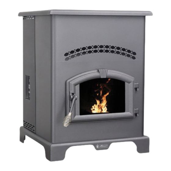
MODEL: AP130
SAVE THESE INSTRUCTIONS
United States Stove Company
227 Industrial Park Road
South Pittsburg, TN 37380
Report #: 215-S-05c-2
Certified to ASTM E 1509, 2012, and Certified to
ULC S627, 2000, and(UM) 84-HUD
This unit is not intended to be used as a
primary source of heat.
U.S. Environmental Protection Agency
Certified to comply with 2015 particulate
emissions standards.
853146C-0203i
Advertisement
Table of Contents

Related Manuals for United States Stove ASHLEY AP130


Summary of Contents for United States Stove ASHLEY AP130
- Page 1 State of California to cause cancer, birth defects and/or other U.S. Environmental Protection Agency Certified to comply with 2015 particulate reproductive harm. For more information, go to www.P65warnings.ca.gov emissions standards. United States Stove Company 227 Industrial Park Road 853146C-0203i South Pittsburg, TN 37380...
-
Page 2: Safety Precautions
Safety Precautions This manual describes the installation and operation of the Ashley, AP130 pellet stove. • IMPORTANT: Read this entire manual before away from all combustible materials, pending final installing and operating this product. Failure to do disposal. so may result in property damage, bodily injury, •... -
Page 3: Specifications
Specifications HEATING SPECIFICATIONS Fuel Burn Rate* 1.5 - 5.0 lbs./hr. (0.7 - 2.3 kg/hr) Burn Time (lowest setting) 80 hrs. Hopper Capacity 130lbs. (59kg) * Pellet size may effect the actual rate of fuel feed and burn times. Fuel feed rates may vary by as much as 20%. Use PFI listed fuel for best results. -
Page 4: Installation
Installation Installation Options Read this entire manual before you install and use your pellet stove. Failure to follow instructions may result in property damage, bodily injury, or even death! (See specific installation details for clearances and other installation requirements) A Freestanding Unit—supported by pedestal/legs and placed on a non-combustible floor surface in compliance with clearance requirements for a freestanding stove installation. - Page 5 CLEARANCES Your pellet stove has been tested and listed for installation in residential, mobile home, and alcove applications in accordance with the clearances given in TABLE 1. NOTE: Distance “B” on the side of your pellet stove may need to be greater than the minimum required clearance for suitable access to the control panel.
-
Page 6: Venting Requirements
VENTING REQUIREMENTS • INSTALL VENT AT CLEARANCES SPECIFIED BY THE VENT MANUFACTURER. • DO NOT CONNECT THE PELLET VENT TO A VENT SERVING ANY OTHER APPLIANCE OR STOVE. • DO NOT INSTALL A FLUE DAMPER IN THE EXHAUST VENTING SYSTEM OF THIS UNIT. The following installation guidelines must be followed to ensure conformity with both the safety listing of this stove and to local building codes. -
Page 7: Vent Termination Clearances
VENT TERMINATION CLEARANCES A. Minimum 4-foot (1.22m) clearance below or beside any door or window that opens. B. Minimum 1-foot (0.3m) clearance above any door or window that opens. C. Minimum 3-foot (0.91m) clearance from any adjacent building. D. Minimum 7-foot (2.13m) clearance from any grade when adjacent to public walkways. -
Page 8: Through The Roof/Ceiling Installation
THROUGH THE ROOF/CEILING INSTALLATION When venting the heater through the ceiling, the pipe is connected the same as through the wall, except the clean-out tee is always on the inside of the house, and a 3 in.(76mm) adapter is added before the clean-out tee. You must use the proper ceiling support flanges and roof flashing (supplied by the pipe manufacturer;... -
Page 9: Understanding Your Stove
Indicator & Button with an automatic ignition system & Button that should ignite the fuel within 5-10 DESCRIPTION HOLES GENERAL NOTES: © 2010 United States Stove Company TOLERANCES .005" ALL RIGHTS RESERVED minutes from pressing the ON button. EXCEPT ALL FORMED DIMENSIONS ARE TO THE DATA CONTAINED HEREIN IS PROPRIETARY TO U. -
Page 10: Control Panel Overview
Control Panel Overview Turning the heater ON/OFF, as well as adjustments for the fuel feed rate and room fan speed are performed by pressing the appropriate button(s) on the control panel which is located on the lower left-hand side of your heater. -
Page 11: Thermostat Hook-Up
Thermostat Hook-Up The Jumper Must Be Removed First 1. Put female terminals on the lead wires to your low voltage thermostat. 2. Plug one thermostat lead onto each of the terminal posts on the circuit board. IMPORTANT NOTE: The purpose of the T’Stat is make stove cycle... -
Page 12: Operation
Operation UNIT PREPARATION After carefully unpacking and reading the instructions for installing your stove, you will need to perform the following steps: • Attach the included spring handle to the door handle by screwing it on in a respective location. •... -
Page 13: Do Not Burn
• DO NOT USE CHEMICALS OR FLUIDS TO START THE FIRE - Never use gasoline, gasoline-type lantern fuel, kerosene, charcoal lighter fluid, or similar liquids to start or “freshen up” a fire in this stove. Keep all such liquids well away from the stove while it is in use. •... -
Page 14: Maintenance
DAILY OPERATION • The hopper and stove top will be hot during operation; therefore, you should always use some type of hand protection when refueling your stove. • Never place your hand near the auger while the stove is in operation. This unit should be filled when the hopper level drops below 3-inches. - Page 15 INTERIOR CHAMBERS Periodically remove and clean the burnpot and the area inside the burnpot housing. In particular it is advisable to clean out the holes in the burnpot to remove any build up that may prevent air from moving through the burn pot freely.
-
Page 16: Spring Shutdown
SPRING SHUTDOWN After the last burn in the spring, remove any remaining pellets from the hopper and the auger feed system. Scoop out the pellets and then run the auger until the hopper is empty and pellets stop flowing (this can be done by pressing the “ON”... -
Page 17: Display Indicators
Error Code Error Description Possible Causes Err1 The high limit temperature sensor has tripped. • Inadequate ventilation. • Room fan failure. • Exhaust Blockage. • Electrical Open in wiring. Err2 Stove ran out of fuel during normal operation. • Hopper Empty. •... -
Page 18: Wiring Diagram
Wiring Diagram -18-... - Page 19 Parts List Part No. Description Qty. 89586 Nipple 69524 Feed Door Assembly 891121 Silicone Hose 3” 891372 Door Hinge Pad 83537 Hose Clamp (#4) 25080B Feed Door Latch 88119 Insulation Blanket 69693 Burnpot Housing Weldment 88168 Burnpot Housing Gasket 86624 Burnpot Assembly 26096MB Hearth 25513...
-
Page 20: Parts Diagram
Parts Diagram -20-... -
Page 21: Service Provider
Service Record It is recommended that your heating system is serviced regularly and that the appropriate Service Interval Record is completed. SERVICE PROVIDER Before completing the appropriate Service Record below, please ensure you have carried out the service as described in the manufacturer’s instructions. Always use the manufacturer's specified spare part when replacement is necessary. - Page 22 2. The part description / La description de la pièce 3. The model number / Le numéro de modèle 4. The serial number / Le numéro de série United States Stove Company 227 Industrial Park Road P.O. Box 151 South Pittsburg, TN 37380 (800) 750-2723 WWW.USSTOVE.COM...
Need help?
Do you have a question about the ASHLEY AP130 and is the answer not in the manual?
Questions and answers