Table of Contents
Advertisement
4
LABELING VENDOR NOTES:
MATERIAL: 0.012 THK. ALUMINUM / 3M 9672 ADEHESIVE BACKED.
FINISH: BLACK BACKGROUND, ALUMINUM TO SHOW THRU
(ALL TEXT AND ILLUSTRATIONS) UNLESS NOTED OTHERWISE.
TEXT: ALL TEXT TO BE 0.07 HIGH UNLESS OTHERWISE SPECIFIED
B
0.25 TEXT HEIGHT
0.125 TEXT HEIGHT
0.10 TEXT HEIGHT
A
SERIAL & DATE BOX
DETAIL
1.50
[38.1mm]
0.25
[6.4mm]
4
3
ALL PLATES ARE TO BE STAMPED BY THE HEATER MFG. WITH A
FACTORY IDENTIFIER NUMBER ISSUED BY USSC. (i.e. 00000-XX)
WHEN LABEL IS APPLIED TO THE HEATER, IT IS TO BE FIRMLY
PRESSED OVER THE ENTIRE SURFACE TO ENSURE IT PROPERLY
1 INCH SQ. BORDER, LOGS
AND FLAMES ARE TO BE RED
0.25 TEXT HEIGHT
ATTENTION:
HOT WHILE IN OPERATION-DO NOT TOUCH
KEEP CHILDREN AND CLOTHING AWAY -
CONTACT MAY CAUSE SKIN BURNS. SEE NAMEPLATE AND
INSTRUCTIONS. KEEP FURNISHINGS AND OTHER COMBUSTIBLE
MATERIALS A CONSIDERABLE DISTANCE AWAY FROM THE APPLIANCE.
ATTENTION:
OPERATE THIS UNIT ONLY WITH THE FUEL HOPPER LID
CLOSED. FAILURE TO DO SO MAY RESULT IN EMISSION OF
PRODUCTS OF COMBUSTION FROM THE HOPPER UNDER CERTAIN CONDITIONS.
MAINTAIN HOPPER SEAL IN GOOD CONDITION. DO NOT OVERFILL THE HOPPER.
CAUTION: Moving parts may cause injury. Do not operate with the side panels or repair panel removed. Do not place hands or fingers in the moving auger area at
the bottom of the hopper. Do not obstruct the combustion air inlet opening at the rear of the appliance.
DANGER: Risk of electrical shock. Disconnect power before servicing unit. Route power supply cord away from the appliance.
Keep viewing and ash removal doors tightly closed during operation. Replace glass with 5mm ceramic glass ONLY.
IMPORTANT: When the hopper lid is open, the auger will stop. Close the hopper lid to allow system to operate. Provide a source of fresh air to the room where the appliance
is installed. Do not obstruct the space beneath the appliance. Inspect and clean exhaust vent system frequently in accordance with manufacturer's instructions.
Install and use only in accordance with the manufacturer's installation and operating instructions. Contact local building or fire officials about restrictions and
installation inspection in your area. Do not install in a sleeping room.
Do not connect this unit to a chimney flue serving another appliance. Refer to local building codes and the installation and operating instructions for precautions
required for passing an exhaust venting system through a combustible wall or ceiling.
Components required for residential or mobile home installation: Model PL Vent Chimney and Components - 3"/75mm or 4" 100mm diameter.
This wood heater needs periodic inspection and repair for proper operation. Consult the owner's manual for further information. It is against federal regulations to
operate this wood heater in a manner inconsistent with the operating instructions in the owner's manual.
START-UP / Automatic Ignition - Press the ON/OFF button. Green power light begins to blink. When the light becomes solid, set the desired heat level.
SHUT DOWN: Press the "OFF" button. Unit will shutdown automatically after fuel burns out and unit cools down.
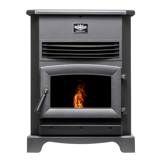
MODEL / MODÈLE : KP130
Serial No. /
o
N
de série
Manufacture Date. /
Date de Fabrication
U.S. Stove Company • 227 Industrial Park Road • South Pittsburg, TN 37380 • Phone: (800) 750-2723 • Web: www.usstove.com
© 2010 United States Stove Company
THE DATA CONTAINED HEREIN IS PROPRIETARY TO U. S.
STOVE COMPANY. THIS DATA SHALL NOT BE DUPLICATED,
TRANSFERRED, MADE AVAILABLE, OR USED BY ANY THIRD
PARTY FOR ANY PURPOSE EXCEPT SPECIFICALLY
AUTHORIZED IN WRITING BY U. S. STOVE COMPANY.
3
HEATER MANUFACTURER INSTRUCTIONS:
ADHERES TO THE MATING SURFACE OF THE HEATER.
0.125 TEXT HEIGHT
ATTENTION:
TOUT CONTACT PEUT ENTRAÎNER DES BRÛLURES. CONSULTER LA PLAQUE
SIGNALÉTIQUE ET LES INSTRUCTIONS. MAINTENIR LE MOBILIER ET LES AUTRES
MATIÈRES COMBUSTIBLES À BONNE DISTANCE DE L'APPAREIL.
ATTENTION:
PAS LE FAIRE PEUT ENTRÎNER DES ÉMISSIONS DE PRODUITS DE LA TRÉMIE DANS
CERTAINES CONDITIONS. D'ASSURER L'ÉTANCHÉITÉ TRÉMIE EN BON ETAT. NE PAS
SURCHARGER LA TRÉMIE.
ATTENTION: Les pièces en mouvement peuvent provoquer des blessures. Ne pas faire fonctionner cette unité avec les panneaux latéraux ou le panneau arrière
retirés. Ne pas placer les mains ou les doigts à l'intérieur de la zone de la vis sans fin en bas de la trémie. N'obstruez pas l'admission d'air de combustion.
DANGER: Risque de choc électrique. Déconnecter l'alimentation avant de réaliser l'entretien de l'unité. Faire passer le cordon d'alimentation à distance de l'unité.
Maintenir les portes d'inspection et de retrait des cendres bien fermées pendent le fonctionnement. Remplacer le verre uniquement par du verre céramique (5mm).
IMPORTANT: Quand le couvercle de la trémie est ouvert, la vis sans fin d'alimentation s'arrêtera. Fermer le couvercle pour permettre au système de fonctionner.
Fournir une source d'air frais dans le chambre. Ne pas obsturer l'espace sous l'app. de chauffage. Inspecter et nettoer fréquemment le système de ventilation
d'évacuation conformément aux instructions du fabricant.
Installer et utiliser conformément aux instructions du fabricant uniquement. Contacter les fonctionnaires locaux de construction ou fonctionnaires des services
d'incendie concernant les limitations et l'inspection de l'installation dans votre maison. Ne pas installer dans une chambre à coucher.
Ne pas connecter cette unité à un carneau de chiminée utilisé pour un autre appareil. Consulter le code local de construction et les instructions du fabricant pour les
précautions requises pour passer à travers un mur ou un plafond combustible.
Composants nécessaires pour une installation dans une résidence ou une maison mobile: Ventilation modèle PL chiminée et composants - Diamètre de 3"/75mm ou
4"/100mm.
Ce poêle à bois doit inspection et la réparation périodique. Pour un fonctionnement correct, consultez le manuel du propriétaire pour plus d'informations. Ce est
contre les règlements fédéraux pour faire fonctionner ce poêle à bois d'une manière incompatible avec les instructions d'utilisation dans le manuel du propriétaire.
MISE en MARCHE / Allumage Automatique - Appuyer sur le buoton ON/OFF. Le voyant vert se met à clignoter. Lorsque le voyant s'arrête de clignoter et reste
allumé, régler le thermostat au niveau souhaité.
ARRÊT: Placer le réglage de chaleur sur "OFF". L'unité s'éteindra automatiquement une fois que le combustible sera consumé et que l'unité ait refroidi.
ENVIRONMENTAL PROTECTION AGENCY
Certified to comply with 2020 particulate
emission standards. Tested to ASTM E2779 /
EPA Method 28R - 1.27 g/hr.
A -
2" / 50mm
B - 13" / 330mm
C -
8" / 203mm
D -
8" / 203mm
E -
36" / 914mm
F -
60" / 1.52M
Report No. / Rapport No.
Report No. / Rapport No.
215-S-05c-2
18-439
DO NOT REMOVE OR COVER THIS LABEL / NE PAS RETIRER OU COUVRIR CETTE ÉTIQUETTE
12.00
[304.8mm]
DESCRIPTION
HOLES
TOLERANCES
± .005"
ALL RIGHTS RESERVED
EXCEPT
DECIMAL
FINISH
.XX = 0.03 XXX = 0.010
AS
ANGULAR
REFERENCE
NOTED
± 2°
2
REV
A
B
0.125 TEXT HEIGHT
0.25 TEXT HEIGHT
CHAUD PENDANT LE FONCTIONNEMENT-NE PAS TOUCHER
MAINTENIR LES ENFANTS ET LES VÊTEMENTS ÉLOIGNÉS.
FAIRE FONCTIONNER CETTE UNITÉ UNIQUEMENT AVEC LE
COUVERCLE DE TRÉMIE DU COMBUSTIBLE FERMÉ. NES
Clearances to Combustibles: Residential and Mobile Home
Dégagements Combustibles: Dans Une Résidence ou Une Maison Mobile
Alcove
Backwall/Sidewall
Corner/Coin
Mur Arriére/Paroi Latérale
A
D
E
A
B
F
C
C
D
SCALE
SIZE
REV
SEE NOTE
1:1
B
B
DWN BY
SEH
TITLE
DATE
CERTIFICATION PLATE
3/4/13
KP130
2
REVISION HISTORY
DESCRIPTION
DATE
BY
INITIAL RELEASE
2/27/18
SEH
3/29/19
SEH
B
5.50
[139.7mm]
1/2"(12.5mm) or 1"(25mm) Thick/Épais
Non-Combustible Floor Protection /
Un Protecteur de sol Non-Combustible
6 in (152mm)
Canada - 8" (203mm)
Thickness /
k-value
1/2" / 0.042
A
1" / 0.084
6 in (152mm)
Canada - 18" (450mm)
853144B
ESTABLISHED 1869
NUMBER
SHEET
853144
1
1
OF
1
Advertisement
Table of Contents

Related Manuals for United States Stove King KP130


Summary of Contents for United States Stove King KP130
- Page 1 U.S. Stove Company • 227 Industrial Park Road • South Pittsburg, TN 37380 • Phone: (800) 750-2723 • Web: www.usstove.com 0.25 [6.4mm] 12.00 [304.8mm] DESCRIPTION SCALE SIZE HOLES © 2010 United States Stove Company TOLERANCES SEE NOTE ± .005" ALL RIGHTS RESERVED EXCEPT ESTABLISHED 1869 DWN BY DECIMAL FINISH THE DATA CONTAINED HEREIN IS PROPRIETARY TO U.
- Page 3 State of California to cause cancer, birth defects and/or other emissions standards. reproductive harm. For more information, go to www.P65warnings.ca.gov United States Stove Company PO Box 151, 227 Industrial Park Rd., South Pittsburg, TN 37380 PH: (800) 750-2723 853143G-4204i www.usstove.com...
-
Page 4: Safety Precautions
Safety Precautions • IMPORTANT: Read this entire manual before installing combustible surface or on the ground, well away and operating this product. Failure to do so may result from all combustible materials, pending final disposal. in property damage, bodily injury, or even death. •... -
Page 5: Specifications
Specifications Heating Specifications Fuel Burn Rate* 1.5 - 5.0 lbs./hr. (0.7 - 2.3 kg/hr) Burn Time (lowest setting) 80 hrs. Hopper Capacity 130lbs. (59kg) * Pellet size may effect the actual rate of fuel feed and burn times. Fuel feed rates may vary by as much as 20%. Use PFI listed fuel for best results. -
Page 6: Installation Options
Installation INSTALLATION OPTIONS Read this entire manual before you install and use your pellet stove. Failure to follow instructions may result in property damage, bodily injury, or even death! (See specific installation details for clearances and other installation requirements) A Freestanding Unit—supported by pedestal/legs and placed on a non-combustible floor surface in compliance with clearance requirements for a freestanding stove installation. - Page 7 CLEARANCES Your pellet stove has been tested and listed for installation in residential, mobile home, and alcove applications in accordance with the clearances given in TABLE 1. NOTE: Distance “B” on the side of your pellet stove may need to be greater than the minimum required clearance for suitable access to the control panel.
-
Page 8: Venting Requirements
VENTING REQUIREMENTS • INSTALL VENT AT CLEARANCES SPECIFIED BY THE VENT MANUFACTURER. • DO NOT CONNECT THE PELLET VENT TO A VENT SERVING ANY OTHER APPLIANCE OR STOVE. • DO NOT INSTALL A FLUE DAMPER IN THE EXHAUST VENTING SYSTEM OF THIS UNIT. The following installation guidelines must be followed to ensure conformity with both the safety listing of this stove and to local building codes. -
Page 9: Vent Termination Clearances
VENT TERMINATION CLEARANCES A. Minimum 4-foot (1.22m) clearance below or beside any door or window that opens. B. Minimum 1-foot (0.3m) clearance above any door or window that opens. C. Minimum 3-foot (0.91m) clearance from any adjacent building. D. Minimum 7-foot (2.13m) clearance from any grade when adjacent to public walkways. -
Page 10: Outside Air Supply
OUTSIDE AIR SUPPLY (OPTIONAL, UNLESS INSTALLING IN A MOBILE HOME) Depending on your location and home construction, outside air may be necessary for optimal performance. Metal pipe (solid or flexible) must be used for the outside air installation. PVC pipe is NOT approved and should NEVER be used. -
Page 11: Understanding Your Stove
Indicator & Button with an automatic ignition system & Button that should ignite the fuel within 5-10 DESCRIPTION HOLES GENERAL NOTES: © 2010 United States Stove Company TOLERANCES .005" ALL RIGHTS RESERVED minutes from pressing the ON button. EXCEPT ALL FORMED DIMENSIONS ARE TO THE DATA CONTAINED HEREIN IS PROPRIETARY TO U. -
Page 12: Control Panel Overview
Control Panel Overview Turning the heater ON/OFF, as well as adjustments for the fuel feed rate and room fan speed are performed by pressing the appropriate button(s) on the control panel which is located on the lower left-hand side of your heater. -
Page 13: Thermostat Hook-Up
Thermostat Hook-Up The Jumper Must Be Removed First 1. Put female terminals on the lead wires to your low voltage thermostat. 2. Plug one thermostat lead onto each of the terminal posts on the circuit board. IMPORTANT NOTE: The purpose of the T’Stat is make stove cycle... -
Page 14: Operation
Operation UNIT PREPARATION After carefully unpacking and reading the instructions for installing your stove, you will need to perform the following steps: • Attach the included spring handle to the door handle by screwing it on in a respective location. •... -
Page 15: Shutdown Procedure
This heater is designed to burn only PFI Premium grade pellets. DO NOT BURN: 1. Garbage; 10. Salt water driftwood or other previously salt water 2. Lawn clippings or yard waste; saturated materials; 3. Materials containing rubber, including tires; 11. Unseasoned wood; or 4. -
Page 16: Maintenance
1. If the stove is still warm, it will resume feeding fuel and continue to operate normally. If the fire has gone out, you will have to press the “OFF” button and then the “ON” button again to begin a new start-up sequence. 2. -
Page 17: Chimney Connector
ASH DISPOSAL Disposal of ashes – Ashes should be placed in a steel container with a tight fitting lid and moved outdoors immediately. The closed container of ashes should be placed on a non-combustible floor or on the ground, well away from combustible materials, pending final disposal. -
Page 18: Troubleshooting
Trouble Shooting • Disconnect the power cord before performing any maintenance! NOTE: Turning the ON/OFF Switch to ”OFF” does not disconnect all power to the electrical components of the stove. • Never try to repair or replace any part of the stove unless instructions for doing so are given in this manual. All other work should be done by a trained technician. -
Page 19: Display Indicators
DISPLAY INDICATORS Several situations or events are indicated in normal operation by blinking display indicators or segments in the display: Flashing On Indicator: This means that the stove is in the “Start Up” state waiting for the ignition procedure to complete. -
Page 20: Wiring Diagram
Wiring Diagram -18-... -
Page 21: Parts List
Parts List Part No. Description Qty. 89586 Nipple 69524 Feed Door Assembly 891121 Silicone Hose 3” 891372 Door Hinge Pad 83537 Hose Clamp (#4) 25080B Feed Door Latch 88119 Insulation Blanket 69693 Burnpot Housing Weldment 88168 Burnpot Housing Gasket 86624 Burnpot Assembly 26096MB Hearth 25513... -
Page 22: Parts Diagram
Parts Diagram -20-... -
Page 23: Service Provider
Service Record It is recommended that your heating system is serviced regularly and that the appropriate Service Interval Record is completed. SERVICE PROVIDER Before completing the appropriate Service Record below, please ensure you have carried out the service as described in the manufacturer’s instructions. Always use the manufacturer's specified spare part when replacement is necessary. - Page 24 2. The part description / La description de la pièce 3. The model number / Le numéro de modèle 4. The serial number / Le numéro de série United States Stove Company 227 Industrial Park Road P.O. Box 151 South Pittsburg, TN 37380 (800) 750-2723 WWW.USSTOVE.COM...
Need help?
Do you have a question about the King KP130 and is the answer not in the manual?
Questions and answers
I need the complete door
The complete door for the United States Stove King KP130 consists of multiple parts, including the feed door (part #25507), door handle (part #25492), door glass (part #891053), rope gasket (part #88066), and glass gasket (part #88087). You can find these parts on platforms that sell US Stove King KP130 pellet stove repair and replacement parts.
This answer is automatically generated