
Related Manuals for Xtreme X90-2S


Summary of Contents for Xtreme X90-2S
- Page 1 X90-2S Modular Three-Phase UPS 140kVA Model User & Installation Manual www.xpcc.com | © 2023 Xtreme Power Conversion Corporation. All rights reserved. (Rev 4/19/23)
-
Page 2: Table Of Contents
Table of Contents 1. Safety ..........................3 1.1 Important Safety Instructions ..................3 1.2 EMC ..........................3 1.3 Installation information ....................3 1.4 Maintenance ......................... 5 1.5 Recycling the used battery .................... 5 2. Installation ........................6 2.1 Initial Inspection ......................6 2.2 Installation Environment.................... -
Page 3: Safety
1. Safety 1.1 Important Safety Instructions This UPS contains LETHAL VOLTAGES. All repairs and service must be performed by AUTHORIZED SERVICE PERSONNEL ONLY. There are NO USER SERVICEABLE PARTS inside the UPS. WARNING: The UPS is designed for commercial and industrial purpose and must not be used for any life ⚫... - Page 4 regulations. The disconnection device should be chosen based on the input current and should break line ⚫ and neutral conductors - four poles for three phases.
-
Page 5: Maintenance
1.4 Maintenance WARNING: Only qualified service personnel should perform the battery installation. ⚫ The following PRECAUTIONS should be observed ⚫ (1.) Remove watches, rings, or other metal objects. (2.) Use tools with insulated handles. (3.) Wear rubber gloves and boots. (4.) Do not lay tools or metal parts on top of batteries or battery cabinets. -
Page 6: Installation
2. Installation 2.1 Initial Inspection Visually examine if there is any damage inside and outside of packages in the process of the transportation. If any damage is found, report it to the carrier immediately. Verify the product label is correct. If the equipment needs to be returned, carefully repack the equipment using the original packing material. -
Page 7: Unpacking
2.3 Unpacking Use a forklift to move the product to installation area. Refer to Figure 2-1. Please make sure the bearing capacity of forklift is sufficient. Please follow the orders in Figure 2-2 to remove carton and foams. Figure 2-1 Figure 2-2... - Page 8 Put the ramp in the front of the cabinet. Refer to Figure 2-3. Ramp Figure 2-3 Remove 2 fixing cabinet plates and loosen leveling feet by rotating them counterclockwise. Then, move the cabinet from the pallet. Refer to Figure 2-4. To fix the cabinet in position, simply rotate leveling feet clockwise.
-
Page 9: Moving The Cabinet
2.4 Moving the Cabinet The UPS is fixed on the pallet with 2 fixing cabinet plates. When removing them, pay attention to the movement of the casters to avoid accidents. The cabinet can be pushed forward or backward only. Pushing it sideward is not allowed. When pushing the cabinet, pay attention not to overturn it as the gravity center is high. -
Page 10: Types Of Ups Cabinet
2.5 UPS Cabinet Model X90-2S Drawing Cabinet Height Monitor Module Max. Power Module Max Power 140kVA... -
Page 11: Exterior
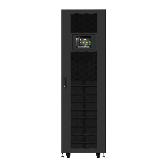
2.6 Exterior On the UPS front door, there are control interface (LCD Panel) and door lock. The side panels are lockable. The casters at the bottom of the UPS cabinet can be used to move the UPS over a short distance. There are four leveling feet to fix and stabilize the UPS cabinet on the ground. - Page 12 2.6.1 Mechanical Data Dimensions Width Depth Height 600mm 1065m 2010mm Figure 2-8 Dimensions...
- Page 13 2.6.2 Front View Unlock and open the front door and you will see a top cover (terminal blocks are behind it), the Main Breaker (Q1), Maintenance Breaker (Q2), Output Breaker (Q3), Monitor Module, Power Module slots and Battery Module slots. Figure 2-9 Front View...
-
Page 14: Internal Mechanisms
2.7 Internal Mechanisms 2.7.1 Breakers There are four breakers: Main Breaker, Maintenance Breaker, Output Breaker and Battery Breaker. Figure 2-11 breakers (front view) 2.7.2 Wiring Terminal Blocks Open the UPS’s front door and remove the top cover, and you will see the wiring terminal blocks. For UPS cabinet wiring, please refer to Figure 2-13. - Page 15 Figure 2-13 Terminal Blocks...
-
Page 16: Control Panel
2.8 Control Panel 2.8.1 LCD Display The touch screen color LCD display shows the UPS’ operation mode. In addition, a user can also view measurement, parameters, versions of firmware, warnings and etc. on the LCD, as well as controlling the UPS and setting various parameters. For detailed information, please refer to Chapter 4. - Page 17 There is neither a fault nor an alarm.
-
Page 18: Introduction Of Modules
2.8.3 Control Key Turn on or turn off the UPS. 2.9 Introduction of Modules The modular and hot-swappable design of the Power Module makes it a highly cost-effective solution to meet your power requirement. The number of Power Modules installed in the UPS can be based on the initial needs. - Page 19 2.9.1 Monitor Module The Monitor Module is installed at factory, which includes communication interfaces. For detailed information, please refer to Chapter 5. Item Description An optional card such as an SNMP, AS400 or Modbus card can be ① SNMP Slot inserted into this slot.
- Page 20 2.9.2 Power Module Each Power Module is shipped in its own package and installed during the UPS system installation. The capacity of each Power Module is 50KVA/50KW or 70kVA/70kW. It includes a power factor correction rectifier, a battery charger, an inverter, STS and control circuit. Item Description These fans provide forced convection cooling.
- Page 21 RACK 1 RACK 2 Module Address DIP SWITCH Module Address DIP SWITCH Table 2-1 DIP switch setting and Module Address Power Module ID Assignment The Power Module address ID assignment is shown in Table 2-1. The DIP switches are mounted ...
-
Page 23: Power Cable
2.10 Power Cable Please follow the local wiring regulations. Consider environmental conditions and refer to IEC60950-1. 2.10.1 AC input and output nominal current and cable fixation force. Power rating 50KVA 100KVA 70KVA 140KVA Output Current (A) Mains Input Current (A) Bypass Input Current (A) Fixation torque force (lb-in) 2.10.2 DC input nominal current and cable fixation force. - Page 24 2.11.1 Installation Drawing Figure 2-18 UPS Cabinet Wiring 2.11.2 AC source connection UPS comes configured for single-input from the factory. Remove jumpers if feeding the UPS with dual inputs. The sequence of three phases, R, S and T, must be connected accordingly. The wrong sequence will alarm a warning when the UPS is powered.
- Page 25 2.11.3 External Battery Cabinet Connection Figure 2-24 External Battery Cabinet Wiring After the battery installation is completed, be sure to set up nominal battery voltage, battery capacity and maximum charging current on LCD. Otherwise, if battery setting is different from actual installation, the UPS will keep warning.
-
Page 26: Power Module Installation
2.12 Power Module Installation The weight of Power Module is over 30Kg. Therefore, at least two people are required for handling it. 2.12.1 Insert the Power Module (1.) Adjust the DIP switch positions to set the different Module Address ID. Refer to Table 2-1. (2.) Switch the ready switch on the front panel of the module to the “... - Page 27 (4.) Secure the Power Module to the cabinet with screws shown below (two on each side). (5.) Move the ready switch to the “ ” position. 2.12.2 Remove the Power Module Before removing any Power Module, make sure the remaining Power Modules ⚫...
- Page 28 (3.) Use a screwdriver to remove the four screws from fixing holes. (4.) Two people pull out together and remove the Power Module from its slot.
-
Page 29: Operation Mode And Ups Operation
3. Operation Mode and UPS Operation 3.1 Block diagram of UPS Wiring diagram for dual inputs Figure 3-1... -
Page 30: Operation Mode
Wiring diagram for single input Figure 3-2 3.2 Operation Mode This modular UPS is a three-phase, four wire on-line, double-conversion and reverse-transfer UPS that permits operation in the following modes: Standby Mode ⚫ Line Mode ⚫ Battery Mode ⚫ Bypass Mode ⚫... - Page 31 Figure 3-3: Standby Mode Diagram 3.2.2 Line Mode In Line Mode, the rectifier derives power from the utility power and supplies DC power to the inverter and the charger to charge the battery. The inverter filters the DC power and converts it into stable pure sinewave AC power to the load.
- Page 32 3.2.3 Battery Mode The UPS automatically transfers to Battery mode if the utility power fails. There is no interruption in power to the load upon utility power failure. In battery mode, the rectifier derives power from the battery and supplies DC power to the inverter. The inverter filters the DC power and converts it into stable pure sinewave AC power to the load.
- Page 33 Figure 3-6: Bypass Mode Diagram 3.2.5 ECO Mode The ECO Mode is enabled through the setting menu of LCD panel. In ECO mode, the load is powered through the static transfer switch when the bypass input voltage and frequency are within the acceptable ranges.
- Page 34 UPS. The rectifier, the charger and the inverter are all in off state. Figure 3-8: Shutdown Mode Diagram 3.2.7 Maintenance bypass Mode A manual bypass switch is available to ensure continuity of power supply to the load when the UPS becomes unavailable e.g.
-
Page 35: Ups Operation
3.3 UPS Operation Do not start the UPS until the installation is completed. ⚫ Make sure the wiring is correct and the power cables are fixed firmly. ⚫ Make sure the Power Modules’ address IDs have been configured. Refer to section 2.9.2 ⚫... - Page 36 Step 4: Switch ON the input breaker (Q1). The UPS will enter Standby Mode, if the setting of Bypass mode is disabled. Or the UPS will enter Bypass Mode, if the setting of Bypass mode is enabled.
- Page 38 Step 5: Make sure that no warning or fault event occurs. If yes, please refer to Chapter 6 Troubleshooting to solve it. Step 6: Press “Power” button for two seconds to turn on the inverter, as shown below. UPS will do self-test and start up the inverter. UPS will enter Line mode when all power modules are ready.
- Page 39 Step 7: Switch ON the output breaker (Q3). AC startup procedure is complete.
- Page 40 3.3.2 Cold Start Startup Step 1: Switch ON the battery Breaker. Step 2: Press the “Battery Start” button on any one of the Power Modules to start up the control power of all Power modules. UPS will enter into Standby mode. Step 3: Please press “POWER”...
- Page 41 Step 4: UPS will enter Battery Mode. Step 5: Switch ON the output breaker (Q3). Cold start startup procedure is complete. 3.3.3 Maintenance Bypass Operation 3.3.3.1 Transfer to maintenance bypass Step 1: Remove the mechanical lock plate of Maintenance Bypass Breaker. Step 2 Make sure the UPS operates in Bypass mode as shown below.
- Page 43 Step 3 Switch ON the Maintenance Bypass Breaker as shown below. Step 4 Switch OFF the Main Breaker (Q1) as shown below. Step 5 Now one can change Power Module or Battery Module. 3.3.3.2 Transfer to UPS Protection Step 1 Make sure the maintenance is complete.
- Page 44 Step 3 Please enter LCD SETUP MENU and choose “SYSTEM” to ensure that the “Bypass mode” is enabled. If the “Bypass mode” is disabled, you have to change it to “enabled”. Then, exit the SETUP menu and check if the UPS operates in bypass mode. Step 4 Turn off Maintenance Bypass Breaker as shown below.
- Page 45 3.3.4 Turn off Operation 3.3.4.1 Turn Off Operation in Bypass Mode/ Standby Mode When the inverter is turned off, the UPS operates in the Standby Mode or Bypass Mode. It depends on the “Bypass Mode” Setting. The LCD screens are shown below. Bypass Mode Setting is Disabled Bypass Mode Setting is Enabled Step 1: Switch OFF the Main Breaker.
- Page 46 UPS stays in Bypass mode and No AC line input is indicated. Step 2: Switch OFF the external power switch to disconnect the AC power to the UPS. Wait until the LCD is OFF. Step 3: Switch OFF the battery breaker if the UPS will be disconnected from AC power for a long time.
- Page 47 Step 1: Press “POWER” button for 2 second to turn off the inverter. Or use the LCD operation (Control➔ Turn Off) to turn off the inverter. The UPS will then tranfer to Standby Mode or Bypass Mode depending on the “Bypass Mode” Setting.
- Page 48 Step 1: Press “POWER” button for 2 seconds to turn off the inverter. Or use the LCD operation (Control➔ Turn Off) to turn off the inverter. The UPS will then tranfer to Standby Mode. Next, follow the procedure in section 3.3.4.1 Turn Off Operation in Bypass Mode/ Standby Mode.
-
Page 49: Control Panel And Display Description
4. Control Panel and Display Description 4.1 Introduction The control panel consists of a touch screen color LCD, LEDs and a power button. The LCD is on the external side of the front door and the LEDs and the power button are on the internal side of the front door. -
Page 50: Screen Description
Bypass circuit is not operating. The UPS is outputting power to the load. LOAD Green The UPS is not outputting power to the load. Load on inverters Green Inverter circuit is not operating. UPS is in battery mode. BATTERY Flashing Battery voltage is low. - Page 51 (2) Module Status: It shows module icons. Touch module icon to enter its measurement screen. The meanings of the icons are listed as below. Module icon Explanation STS module with ID no. (X90-2S does not have a separate STS module) Power module icon with ID no. No power module...
- Page 52 (3) Main Menu: Touch icon to enter sub screen. Figure 4-4 Menu tree (4) UPS Flow Chart: Current flow chart and measurement data. (5) UPS power rating. (6) Date and Time. 4.2.3 Control Screen Touch icon to enter the sub-menu as shown in Figure 4-5 and 4-6. Figure 4-5 Control menu tree...
- Page 53 Figure 4-6 Control screen page...
- Page 54 Touch any control option. Then, confirmation screen will pop up. Touch icon to confirm command or touch icon to cancel command as shown in Figure 4-7. Figure 4-7 Confirmation screen 4.2.5 Measurement Screen Touch icon to enter the sub-menu. There are two sub-menus, system measurement and module measurement.
- Page 55 Figure 4-9 System Measurement Screens...
- Page 56 Figure 4-10 Module Measurement Screens...
- Page 57 Table 4-4: Measurement item list Menu Item Explanation L-N Voltage (V) Input phase voltage (L1, L2, L3), accuracy: 0.1V Input Frequency (Hz) Input Frequency (L1, L2, L3), accuracy: 0.1Hz L-N Voltage (V) Output phase voltage (L1, L2, L3), accuracy: 0.1V L-N Current (A) Output phase current (L1, L2, L3), accuracy: 0.1A Output...
- Page 58 Figure 4-12 Enter password screen There are two levels of password protection, user password and maintainer password. The user password is defaulted to be “0000”, but can be changed by a user. The maintainer password is owned by service personnel. User password and maintainer password allow access to different settings.
- Page 59 Redundancy Power Rating Setting Nominal Battery Voltage Battery Capacity in Ah Maximum Charging Current Battery Low/Shutdown Setting Periodic Battery Test Battery Test Interval Stop by Time Stop by Battery Voltage Stop by Battery Capacity Battery Age Alert Temperature Compensation Charging Voltage Line Voltage Range...
- Page 60 Figure 4-13 Setting change procedure 4.2.6.1 Setup-General Screen The Setup-General screen and its setting list are shown in Figure 4-14 and Table 4-6. General setting can be set in any operation mode. Figure 4-14 Setup-General screen Table 4-6: Setup-General setting list Setting Item Sub Item Explanation...
- Page 61 2015/1/1 (Default) MUST be set after UPS installation. Set system latest maintenance date System Last Maintain (yyyy / mm / dd) Date MUST be set after UPS installation and each system maintenance. Set battery installation date Battery Installation (yyyy / mm / dd) Date MUST be set after UPS installation.
- Page 62 EPO Function Save Setting Output Voltage Bypass Voltage Range Bypass Frequency Range Converter Mode ECO Mode Bypass Mode System Auto-Restart Battery Mode Delay Time System Shutdown Time System Restore Time Redundancy Power Rating Setting Charger Test Nominal Battery Voltage Battery Capacity in Ah Maximum Charging Current Battery Low/Shutdown Setting Periodic Battery Test...
- Page 63 Figure 4-15 Setup-System screen Figure 4-16 Warning screen Table 4-8: Setup-System setting list Setting Item Sub Item Explanation Set UPS output voltage Output ⚫ 480Vac Voltage MUST be reviewed after UPS installation. BYPASS Set bypass voltage range: Bypass Voltage Range SETTING Upper limit...
- Page 64 ⚫ +10% ⚫ +15% ⚫ +20% (Default) Lower limit ⚫ -10% ⚫ -20% ⚫ -30% (Default) Set bypass Frequency range: Upper/ Lower limit Bypass Frequency ⚫ +/- 1Hz Range ⚫ +/- 2Hz ⚫ +/- 4Hz (Default) Set converter mode ⚫ Disable (Default) Converter ⚫...
- Page 65 This delay timer will start counting after system shutdown time has elapsed. Set power rating value per module Power rating ⚫ 50KVA setting ⚫ 70KVA Set total power and redundancy Redundancy: the QTY of redundant power module Redundancy MUST be set after UPS installation and after the QTY of Power Modules is changed.
- Page 66 Shutdown ⚫ 11.4V (Default) x Battery Number Setting Set battery low capacity (20~50%) Low Capacity ⚫ 20% (Default) Set battery voltage point for system shutdown in battery Shutdown Voltage mode (10.0~11V) x (battery Number) ⚫ 10.7V (Default) x Battery Number Set periodic battery test disable or enable Periodic Battery ⚫...
- Page 67 Figure 4-18 Setup-Pre-Alarm screen Table 4-10: Setup-Pre-Alarm setting list Setting Item Sub Item Explanation Set line voltage range: Upper limit ⚫ +5% ⚫ +10% ⚫ +15% Line Voltage ⚫ +20% (Default) Range Lower limit ⚫ -5% ⚫ -10% ⚫ -15% ⚫...
- Page 68 Figure 4-19 Setup-OTHERS screen 4.2.7 Information Screen Touch icon to enter the sub-menu. On Information screen, you can check the configurations of the unit. There are three sub-menus: Identification, System and Battery. Figure 4-20 Information menu 4.2.7.1 INFORMATION - Identification Screen Under “IDENTIFICATION”...
- Page 69 4.2.7.2 INFORMATION - System Screen Under “SYSTEM” submenu are displayed the system power, nominal voltage, nominal frequency … etc. as shown in Figure 4-22 and 4-23. Touch UP and DOWN arrows to switch between different pages. Figure 4-22 INFORMATION System screen page 1 Figure 4-23 INFORMATION System screen page 2 4.2.7.2 INFORMATION - Battery Screen Under “BATTERY”...
- Page 70 Figure 4-24 INFORMATION Battery screen page 4.2.8 Events Screen When an event occurs, you will see flashing icon on the Main Screen as shown in Figure 4-25. Touch icon to check the latest event list, history event or to reset all events as shown in Figure 4-26.
- Page 71 Figure 4-26 Events menu 4.2.8.1 Current Events Under “CURRENT EVENT” submenu is a list of current events. Each event entry shows the module ID# and event description. There can be up to 50 events in the list, with up to 10 events to be displayed per page.
- Page 72 Figure 4-28 History Events screen 4.2.8.3 Reset All Events The Maintainer password is required to enter Reset All Events screen as shown in Figure 4-29. After the correct Maintainer password is entered, a screen will pop up to ask for confirmation. Touch icon to reset all events or touch icon to cancel, as shown in Figure 4-30.
-
Page 73: Alarm List
Figure 4-30 Reset All Events Confirmation screen 4.3 Alarm List In Table 4-12 is the complete list of UPS alarm messages. Table 4-12: Alarm List Text recorded in event lists shown Explanation on the LCD Fault! <01>Bus start fail BUS soft start failed Fault! <02>Bus over BUS voltage high Fault! <03>Bus under... - Page 74 Fault! <41>Over temp Over temperature Fault! <42>DSP commu fail DSP communication failed Fault! <43>Overload Heavy overload causes UPS to fault Fault! <45>Charger error As stated Fault! <46>Incorrect UPS set Incorrect UPS setting Fault! <47>DSP&MCU commu fail MCU communication failed Fault! <49>In&out phase incomp Input and output phase error Fault! <61>BYP SCR SC Bypass SCR short circuited...
-
Page 75: History Record
Warning! <34> AC input CURR unb Three-phase AC input current unbalanced Warning! <35> Bat Phase loss Battery phase loss Warning! <36> INV CURR unb Inverter current unbalanced Warning! <3A> maintain is open Cover of maintain switch is open Warning! <3B> Auto Adapt Fail Phase Auto Adapt failed Warning! <3C>... - Page 76 Table 4-14: UPS mode changes Item Item Description Description UPS Mode! Power On Mode UPS Mode! Standby Mode UPS Mode! Bypass Mode UPS Mode! Line Mode UPS Mode! Battery Mode UPS Mode! Battery Test Mode UPS Mode! Fault Mode UPS Mode! Converter Mode UPS Mode! ECO Mode UPS Mode! Shutdown Mode UPS Mode! Un-Connection...
-
Page 77: Interface And Communication
5. Interface and Communication 5.1 Dry Contact Port As shown in figure 5-1, the Monitor Module includes dry contact ports (③~④), Extra Comm. slot, SNMP slot, LCD connection port, STS Power LED and serial communication ports (RS232 port, USB port, RJ45 to RS232 port) on the front panel. Figure 5-1 Front view of Monitor module 5.1.1 X1-Remote EPO Input Port The Emergency Power off (EPO) function in UPS can be operated by an assigned remote contact. -
Page 78: Extra Comm. Slot
5-2. Figure 5-3 Maintenance Bypass Switch State port Table 5-2: Description of Maintenance Bypass Switch State port Name Position Description Maintain Bypass Pin1 X2.1 Maintenance bypass switch state Maintain Bypass Pin 2 X2.2 Maintenance bypass switch state X2.3 No use X2.4 No use 5.2 Extra Comm. -
Page 79: Troubleshooting
6. Troubleshooting A user will need to contact authorized service personnel to troubleshoot most of the Faults and Warnings. LCD Message Explanation Solution Fault! Bus Over Voltage DC bus voltage is too high. Contact service personnel. Fault! Bus Under Voltage DC bus voltage is too low. - Page 80 Check if the pre-installed connector Warning! EPO Active Check the EPO connector shorting X1.1 & X1.2 is loose or unplugged. The load is demanding more power than Warning! Over Load Fail the UPS can supply. UPS will transfer Lower the load within UPS capacity from Line mode to Bypass mode.
-
Page 81: Service
7. Service This chapter is about servicing the UPS, including the service procedures of the power module, control module and the replacement of air filter. Warning: 1. Only authorized service personnel can service the power modules and battery modules. 2. Remove the power modules and battery modules from top to bottom to prevent the cabinet from toppling due to high center of gravity. - Page 82 The procedure for replacing an air filter is: 1. Open the front door of the UPS and you will see the air filters on the back of the door. 2. Remove a fixing bar on either side of the air filter to replace. 3.
-
Page 83: Specifications
8. Specifications The chapter lists the specifications of UPS. 8.1 Conformity And Standards The UPS has been designed to conform to the European and international standards listed in Table 8-1. Table 8-1: European and international standards * Safety Safety Conformance: IEC/EN 62040-1,UL1778 (5th Edition) Safety Markings : cTUVus, CE * EMI Conducted Emission......: FCC PART15 CLASS A... -
Page 84: Electrical Characteristics (Input Rectifier)
Dimensions, W x D x H 750 x 438 x 130 750 x 438 x 130 Weight 8.4 Electrical Characteristics (Input Rectifier) Table 8-4: Rectifier AC input (mains) Rated power (kVA) Unit 50~140 Rated AC input voltage 480(Ph-Ph) Input voltage tolerance 383~520;... -
Page 85: Electrical Characteristics (Bypass Mains Input)
Overload 105%~110% for 60min 110%~125% for 10min 126%~150% for 1min >150% for 200ms Steady state voltage stability ±1 (balanced load), ±2 (100% unbalanced load) Total harmonic voltage <2 (linear load), <4 (non-linear load) Synchronization window +/- 1Hz, +/- 2Hz, +/- 4Hz (default: 4Hz) Output rated current 140kVA/140kW (480V) - Page 86 Power rating 50kVA/50kW 70kVA/70kW 100kVA/100kW 140kVA/140kW CABINET X90-2S UPS: power modules Up to 140kW (2 x 70kW) or up to 100kVA (2 x 50kW) X90-2S UPS: battery modules 4, 8, 12, 16 or 20 battery modules CAPACITY X90-BC: battery modules...
- Page 87 X90-2S-Series products from the date of purchase. XPC Corporation warrants internal batteries for a period of two years from the date of purchase. For equipment sites within the United States and Canada, this warranty covers repair or replacement, at the sole discretion of XPC Corporation.
Need help?
Do you have a question about the X90-2S and is the answer not in the manual?
Questions and answers