Table of Contents
Advertisement
Quick Links
Advertisement
Table of Contents

Related Manuals for Xtreme P90L-1500


Summary of Contents for Xtreme P90L-1500
- Page 1 For more information, visit P90L Online UPS P90L-1500, 2000, 3000 Models User & Installation Manual © 2015 Xtreme Power Conversion Corporation. All rights reserved. (Rev 4/08/15)
-
Page 2: Table Of Contents
Button Operation...........................18 LCD Panel............................18 Audible Alarms..........................20 Abbreviations in LCD Display......................20 UPS Setting............................21 Operating Mode Description......................25 Fault Reference Codes........................26 Warning Indicators........................27 Troubleshooting..................28 Storage And Maintenance................30 Storage............................30 Maintenance..........................30 Batteries.....................30 Specifications.....................31 Shipping List (UPS)..................32 Shipping List (Battery Pack)................32 Xtreme Power Conversion Corporation Page 2... - Page 3 P90L 1500–3000 User’s Manual Uninterruptible Power Supply Obtaining Service..................33 Xtreme Power Conversion Limited Warranty..........34 Xtreme Power Conversion Load Protection Policy........35 Appendix A: P90-BP36, P90-BP48 & P90-BP72 User Guide......38 Important Safety Instructions......................38 Product Overview and Setup......................38 Type of Battery Required.......................40 Battery Replacement........................41 Wiring Diagram..........................
- Page 4 Thank you for selecting this uninterruptible power supply (UPS). It provides you with protection for connected equipment. Please read this manual before installing the P90L-Series UPS models P90L-1500, P90L-2000 and P90L- 3000 as it provides important information that should be followed during installation and maintenance of the UPS and batteries, allowing you to correctly set up your system for the maximum safety and performance.
- Page 5 RJ45 RECEPTACLE – The receptacle provides network interface connections and telephone or telecommu- nications equipment should not be plugged into it. Please do not discard the UPS or the UPS batteries as the UPS may have valve-regulated lead-acid batter- ies. Please recycle batteries appropriately. Xtreme Power Conversion Corporation Page 5...
-
Page 6: Introduction
• DC power is converted to AC in the inverter, passing it on to the load. • Power is maintained from the battery during a power failure. • The converter increases voltage appropriately for the inverter. Xtreme Power Conversion Corporation Page 6... -
Page 7: Diagnostic Tests
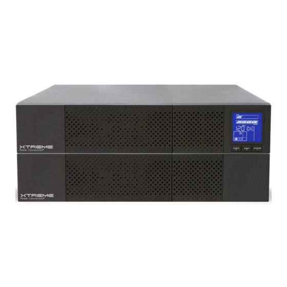
Connectivity Options – Web/SNMP Card, Relay Card, Modbus Card Extended Battery Packs - minimum 1 required, rail kits, bypass switches See the Specification section of this manual for additional model information. P90L front view P90L-1500 rear view P90L-2000 rear view Xtreme Power Conversion Corporation Page 7... - Page 8 P90L 1500–3000 User’s Manual Uninterruptible Power Supply P90L-3000 rear view Front panel Selector buttons Rack display Xtreme Power Conversion Corporation Page 8...
-
Page 9: Communication Connections
It can support op- erating systems such as HP Open View, IBM Netview, SUN Netmanager, etc. This enables the UPS to provide instant UPS and power information over the network. Please contact your reseller for additional details. Xtreme Power Conversion Corporation Page 9... -
Page 10: Emergency Power Off (Epo) Port
The UPS will have to be manually restarted in order to regain power to the outlets on the UPS. Keep Pin 1 and Pin 2 closed for UPS normal operation. To activate EPO function, open the wire between Pin 1 and Pin 2. Xtreme Power Conversion Corporation Page 10... -
Page 11: Hardware Installation Guide
• Space and ventilation requirements must be met. Ensure there is 100mm behind and 50mm on the sides of the UPS for proper ventilation. • Ensure that the front of the UPS remains clear for user operation. Xtreme Power Conversion Corporation Page 11... -
Page 12: Ups Installation
For safety considerations, the UPS is shipped from the factory with battery wires. Connecting Battery Packs Connect external battery pack(s) in accordance with the diagrams below. P90L-1500 rear view Battery pack rear view Xtreme Power Conversion Corporation Page 12... - Page 13 Slide the UPS into the rack and secure using hardware provided Rack-mount Installation (using 4-post rail kit) Package contents • Right and left rail sliders, 1 each • (2) M6 nuts • (12) M6 screws Xtreme Power Conversion Corporation Page 13...
- Page 14 Use 4 screws to mount right and left rail sliders in front of rack. Step 2 Use 4 screws to mount right and left rail sliders in back of rack. Step 3 Place the nuts in the proper location in the rack based upon height of UPS. Xtreme Power Conversion Corporation Page 14...
- Page 15 P90L 1500–3000 User’s Manual Uninterruptible Power Supply Step 4 Carefully place the UPS on the rail support. Step 5 Fix the UPS in position with screws. Step 6 Rail kit installation is now complete. Xtreme Power Conversion Corporation Page 15...
- Page 16 Inter-connect the tower brackets that shipped in the box with the UPS Step 2 Carefully lower the UPS into the brackets as shown Step 3 Your UPS is now mounted as shown in the tower position Xtreme Power Conversion Corporation Page 16...
-
Page 17: Starting The Ups
UPS. UPS Output There are two types of output on the P90L-1500, P90L-2000, and P90L-3000 models - programmable outlets and general outlets. Please connect non-critical devices to the programmable outlets and critical devices to the general outlets. During power failure, you may extend the backup time to critical devices by setting shorter backup time for non-critical devices. -
Page 18: Operations
SELECT buttons simultaneously for 5 seconds. The UPS will then enter ON/Mute + Select Button Bypass mode. The Bypass mode will be disabled when the input voltage is out of acceptable range. LCD Panel Rack Display Tower Display Xtreme Power Conversion Corporation Page 18... - Page 19 Indicates the UPS is working in converter mode. Indicates the UPS is working in bypass mode. Indicates the UPS is powering the output directly from utility. Indicates that the UPS alarm is disabled. Indicates the battery charger is working. Xtreme Power Conversion Corporation Page 19...
-
Page 20: Audible Alarms
Sounds every second Overload Sounding twice every second Fault Continuously sounds Abbreviations in LCD Display Abbreviation Display Meaning Enable Disable Escape Rack Display Tower Display Low Battery Overload Battery is not connected Overcharge Site Fault Xtreme Power Conversion Corporation Page 20... -
Page 21: Ups Setting
01: Output Voltage Settings Interface Setting You may choose the following output voltage: 110: presents output voltage as 110VAC 115: presents output voltage as 115VAC 120: presents output voltage as 120VAC 127: presents output voltage as 127VAC Xtreme Power Conversion Corporation Page 21... - Page 22 If converter mode is enabled, you may choose the fol- lowing output frequency: CF 50: sets output frequency to 50Hz CF 60: sets output frequency to 60Hz 04: ECO enable/disable Interface Setting ENA: ECO mode enable DIS: ECO mode disable Xtreme Power Conversion Corporation Page 22...
- Page 23 ENA: Advanced ECO mode enable DIS: Advanced ECO mode disable 06: Bypass Mode enable/disable Interface Setting ENA: Bypass mode enable DIS: Bypass mode disable 07: Programmable Outlets enable/disable Interface Setting ENA: Programmable outlets enable DIS: Programmable outlets disable Xtreme Power Conversion Corporation Page 23...
- Page 24 55/150 alternating flashing: acceptable input voltage range is from 55V to 150V 80/130 alternating flashing: acceptable input voltage range is from 80V to 130V 85/135 alternating flashing: acceptable input voltage range is from 85V to 135V 00: Exit Setting Xtreme Power Conversion Corporation Page 24...
-
Page 25: Operating Mode Description
Static bypass When the input voltage is be- yond the acceptable range or there is a power failure and Battery Mode alarm is sounding every 4 seconds, the UPS will provide backup power from battery. Xtreme Power Conversion Corporation Page 25... -
Page 26: Fault Reference Codes
Icon Bus start failure Inverter output short Bus over Battery voltage too high Bus under Battery voltage too low Bus unbalanced Over temperature Inverter soft start fail Overload High inverter voltage Low inverter voltage Xtreme Power Conversion Corporation Page 26... -
Page 27: Warning Indicators
Sounds every second EPO enable Sounds every second Over temperature Sounds every second Charger failure Sounds every second Battery fault Sounds every second Bypass out of range Sounds every second Bypass frequency unstable Sounds every second Xtreme Power Conversion Corporation Page 27... -
Page 28: Troubleshooting
Disconnect loads and check to see Fault code is shown as 14 and because short circuit condition oc- if output wiring or connected devic- alarm is sounding continuously. curred on the UPS output. es are in short circuit status. Xtreme Power Conversion Corporation Page 28... - Page 29 Batteries are not fully charged. If the problem still exists, contact Battery backup time is shorter than your dealer for support. expected. Contact your dealer for battery Batteries are defective. replacement. Xtreme Power Conversion Corporation Page 29...
-
Page 30: Storage And Maintenance
The life of batteries used in these UPS products is estimated at 3-6 years depending on level of usage. Once the battery is no longer useful and must be replaced, please contact service personnel for assistance. Xtreme Power Conversion Corporation Page 30... -
Page 31: Specifications
Software CD, horizontal brackets, tower pedestals, 16 in battery cable kit AVAILABLE OPTIONS 5 year extended warranty, bypass distribution (XBDM), power distribution (XPDU), 4-post rail kit, 2-post shelf kit *Depending on load level; **P90L capacity derates 20% at 100V output voltage Xtreme Power Conversion Corporation Page 31... -
Page 32: Shipping List (Ups)
5. 4ft USB cable 6. Battery cable for UPS to external battery pack (customer supplied) Shipping List (Battery Pack) 1. UPS - EBP Anderson cable assembly 2. Manual 3. Tower stand brackets 4. Horizontal brackets Xtreme Power Conversion Corporation Page 32... -
Page 33: Obtaining Service
2. Verify there are no circuit breakers tripped. 3. Call your dealer for assistance. If you cannot reach your dealer, or if they cannot resolve the problem, call Xtreme Power Conversion Corp Technical Support at 800.582.4524. Technical support inquiries can also be made at support@xpcc.com. -
Page 34: Xtreme Power Conversion Limited Warranty
Any technical advice furnished by XPC Corporation or a XPC Corpora- tion authorized representative before or after delivery with regard to the use or application of Xtreme Power Con- version equipment is furnished on the basis that it represents XPC Corporations best judgment under the situation and circumstances, but it is used at the recipient’s sole risk. -
Page 35: Xtreme Power Conversion Load Protection Policy
P90L 1500–3000 User’s Manual Uninterruptible Power Supply Xtreme Power Conversion Load Protection Policy THIS POLICY IS NOT A WARRANTY. REFER TO THE XPC CORPORATION, INC. LIMITED WARRANTY FOR INFORMATION CONCERNING THE WARRANTY FOR YOUR XPC PRODUCT. THE LIMITATIONS AND CONDITIONS CONTAINED IN THIS POLICY DO NOT AFFECT THE TERMS OF THE XPC LIMITED WARRANTY. - Page 36 Purchaser and the name of the power utility supplier for the location of the Connected Equipment. XPC will forward to the Purchaser a Load Protection Policy claims form, which Xtreme Power Conversion Corporation Page 36...
- Page 37 No employee of XPC or any other party is authorized to make any representations beyond those made in this agreement con- cerning the Load Protection Policy. XPC Corporation 230 Yuma Street Denver, CO 80223 1.800.582.4524 Xtreme Power Conversion Corporation Page 37...
-
Page 38: Appendix A: P90-Bp36, P90-Bp48 & P90-Bp72 User Guide
• Do not plug or unplug the battery connector if UPS works in DC (discharging) mode. Product Overview and Setup NOTE: Before installation, please inspect the unit. Be sure that nothing inside the package is damaged. Please keep the original package in a safe place for future use. Xtreme Power Conversion Corporation Page 38... - Page 39 3. Please ensure the installation site environmental conditions are in accordance with the unit’s working specifications to avoid overheat and excessive moisture. 4. Do not place the unit in a dusty or corrosive environment or near any flammable objects. 5. This unit is not designed for outdoor use. Xtreme Power Conversion Corporation Page 39...
-
Page 40: Type Of Battery Required
This battery box has been designed to operate with the following types of batteries: 36V/9Ah Version: 3 pieces of 12V 9Ah batteries per string 48V/9Ah Version: 4 pieces of 12V 9Ah batteries per string 72V/9Ah Version: 6 pieces of 12V 9Ah batteries per string Xtreme Power Conversion Corporation Page 40... -
Page 41: Battery Replacement
Step 4: Remove the metal top cover of the battery box by unscrewing 6 screws present on the two sides (3 on the right side and 3 on the left side), 3 screws on the top and 4 screws on the back side. Xtreme Power Conversion Corporation Page 41... - Page 42 Note: To install the second string of batteries, repeat the same procedure on the right side of battery box. Step 7: Connect all batteries following the wiring diagram shown in next chapter. Step 8: Put all batteries inside and secure in place with hold down brackets. Xtreme Power Conversion Corporation Page 42...
- Page 43 Step 4: Remove the metal top cover of the battery box by unscrewing 8 screws present on the two sides (4 on the right side and 4 on the left side), 3 screws on the top and 4 screws on the back side. Xtreme Power Conversion Corporation Page 43...
- Page 44 Note: To install the second string of batteries, repeat the same procedure on the right side of battery box. Step 7: Connect all batteries following the wiring diagram shown in next chapter. Step 8: Put all batteries inside and secure in place with hold down brackets. Xtreme Power Conversion Corporation Page 44...
- Page 45 Step 4: Remove the metal top cover of the battery box by unscrewing 8 screws present on the two sides (4 on the right side and 4 on the left side), 3 screws on the top and 4 screws on the back side. Xtreme Power Conversion Corporation Page 45...
- Page 46 Note: To install the second string of batteries, repeat the same procedure on the right side of battery box. Step 7: Connect all batteries following the wiring diagram shown in next chapter. Step 8: Put all batteries inside and secure in place with the hold down brackets. Xtreme Power Conversion Corporation Page 46...
-
Page 47: Wiring Diagram
Step 9: Put the metal top cover back on the unit. Close the front fixing plate and the two parts of the front panel and secure it with screws. Step 10: Connect the battery box to the UPS. Wiring Diagram P90-BP36 Xtreme Power Conversion Corporation Page 47... - Page 48 Note: The cable connection from the external battery connector to PCB is already present inside the battery box. All the other cable connections should be made in accordance with the above wiring diagram. P90-BP48 1st battery bench Batt Link PCBA + Batt Link PCBA - BLACK Breaker BLACK 2nd battery bench Xtreme Power Conversion Corporation Page 48...
- Page 49 Note: The cable connection from the external battery connector to PCB is already present inside the battery box. All the other cable connections should be made in accordance with the above wiring diagram. P90-BP72 1st battery bench Batt Link PCBA + Batt Link PCBA - BLACK Breaker BLACK 2nd battery bench Xtreme Power Conversion Corporation Page 49...
-
Page 50: Storage & Maintenance
Every 3 months -25°C - 40°C 1-2 hours 40°C - 45°C 1-2 hours Every 2 months 1349 Old 41 Hwy Suite 135, Marietta, GA 30060 Phone: (770) 971 8480 Fax: (770) 514 8415 www.247technology.com info@247technology.com Xtreme Power Conversion Corporation Page 50...
Need help?
Do you have a question about the P90L-1500 and is the answer not in the manual?
Questions and answers