Table of Contents
Advertisement
Quick Links
Advertisement
Table of Contents

Related Manuals for Barrus Shire 90


Summary of Contents for Barrus Shire 90
- Page 1 ORIGINAL INSTRUCTION CANAL ENGINE MANUAL For the following engine model*: Shire 90 *Standard Model, there may be a number of optional extras, or alternative components, that might be fitted to an engine that are not shown in this book. RDG603A23 – Issue 20...
- Page 2 SAFETY E.P. Barrus is concerned for your safety. We use safety statements throughout the manual to call your attention to the potential hazards associated with the operation of your Shire engine. Follow the precautions listed throughout the manual before operation, during operation and during servicing/maintenance procedures for your safety, the safety of others and to protect the performance of your engine.
- Page 3 Shire Engine Manuals and Shire Parts Books To access the Shire Engine Manuals and Shire Parts Books on the internet type the following short links into your search engine: https://www.barrus.co.uk/shire-manuals/ https://www.barrus.co.uk/shire-parts/ RDG603A23 – Issue 20 Page 3 of 84...
- Page 4 A TRANSFER OF TITLE OCCURS, IT MUST ALWAYS BE HANDED OVER TO THE NEW OWNER. Thank you for purchasing this Shire Canal Boat Marine Engine from E.P.Barrus. This manual has been compiled to help you to operate your engine and its associated parts with safety and pleasure.
- Page 5 • The maintenance has been completed to the full requirements, using genuine parts and recorded in the manual. SAFETY E.P Barrus staff or their representatives can only carry out warranty repairs if there is suitable and safe access to the boat and engine room. RDG603A23 – Issue 20...
- Page 6 Routine maintenance outlined in the Owner’s Manual must be performed using genuine parts in order to maintain warranty coverage. If the customer performs maintenance to an insufficient level, Barrus reserves the right to withdraw warranty coverage. RDG603A23 – Issue 20...
- Page 7 WARRANTY CLAIMS Warranty claims must be made by either an authorised dealer or directly to EP Barrus. The dealer or boat builder will arrange for the inspection and any necessary repairs. If the repairs carried out are not covered by the warranty, the purchaser shall pay for all related labour and material, and any other expenses associated with that service.
- Page 8 TRANSFER OF WARRANTY The warranty is valid for the first owner of the Shire engine and is transferrable only at the discretion of EP Barrus Ltd. River Canal Rescue Membership RCR offer a number of support packages and services to give the inland boater peace of mind in the event of an incident, breakdown or emergency.
-
Page 9: Table Of Contents
Exhaust System ......................13 Launching and Lifting Boats..................13 Batteries........................13 SECTION 2 – Engine Identification...................15 SECTION 3 – Component Identification ................16 Shire 90 ........................16 SECTION 4 – Control Panel ....................17 Deluxe Control Panel ....................17 Control Panel Overview .....................17 Warning Light Procedure ...................17 Overall Dimensions of the Deluxe Control Panel ............20... - Page 10 Calorifier ........................30 Control Cables ......................31 Domestic Battery Bank ....................31 Control Panel ......................32 Exhaust System ......................33 Hydraulic Drive Transmissions ..................34 PRM 280DP Gearbox with Power Take Off (Option – RDG914A198) .......35 Electric Start Motor ....................35 Installation Check List ....................36 SECTION 6 – Operation .....................37 Starting the engine for the first time ................37 Starting Procedure .....................37 Stopping Procedure ....................38...
- Page 11 SECTION 8 – Service Schedule ..................50 Specifications and Capacities ..................50 Service Intervals ......................51 SECTION 9 – Wiring Diagrams ..................52 Engine Wiring Diagram Shire 90 ................52 Deluxe Control Panel Wiring Diagram ...............53 5kW ‘E’ Kit System ....................54 Prestolite 24 Volt 120 Amp Alternator Wiring Diagram ..........54 SECTION 10 –...
-
Page 12: Section 1 - Safety Precautions
SECTION 1 – Safety Precautions 1. General NOTICE: NEVER PERMIT ANYONE TO OPERATE THE ENGINE WITHOUT PROPER TRAINING. It is the responsibility of the installer/operator to ensure that the finished installation complies with CE Marking, UKCA Marking, relevant Health & Safety requirements, the Recreational Craft Directive and or any other legislative requirements before commissioning. -
Page 13: Exhaust System
The engine and its accessories are not intended to be put into operation until they are integrated into the boat as a whole. No person should be in the engine compartment and the engine cover or deck hatches should be closed whilst the engine is running. 4. - Page 14 WARNING: BURN HAZARD! BATTERIES CONTAIN SULPHURIC ACID. NEVER ALLOW BATTERY FLUID TO COME IN CONTACT WITH SKIN, EYES OR CLOTHING. SEVERE BURNS COULD RESULT. MAKE SURE THE CORRECT PERSONAL PROTECTION EQUIPMENT IS WORN. • Batteries can produce explosive gases; keep sparks and flames away from the battery. NO SMOKING •...
-
Page 15: Section 2 - Engine Identification
SECTION 2 – Engine Identification The engine serial number can be found engraved into the brass plate on the top of the engine rocker cover and stamped to the crankcase next to the starter motor. The Canal Boat Engines (CB) do not have identification initials on the engraved plate. An example of the engine identification plate is shown below (Figure 1): Description Engine Model... -
Page 16: Section 3 - Component Identification
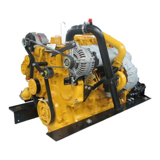
SECTION 3 – Component Identification 1. Shire 90 Description* 120 Amp 12 Volt Alternator 150 Amp 12 Volt Alternator Figure 2: Shire 90 Left Side (Viewed from front) Description* Gearbox Primary Fuel Filter Gearbox Drain Pump Oil Cooler Secondary Fuel Filter... -
Page 17: Section 4 - Control Panel
Please note that on certain Shire engines a different type of control panel can be ordered as an option. Engine Control Panel Supplied* Shire 90 Deluxe Control Panel * Panel supplied as standard. On certain engines a different control panel may be supplied as an option 3. - Page 18 • The water temperature warning light will only come on for a brief period of time when the ignition is first turned on as a bulb check. It will then only illuminate in the case of the engine coolant temperature exceeding the maximum safety level. •...
- Page 19 Description Procedure for Warning Light Tachometer Gauge Hour Meter Reduce the engine revs and stop the engine within one or two minutes. Check the coolant level (refer to 9. Cooling System of SECTION 7 - SERVICE PROCEDURE). If the coolant level is incorrect, fill it to the correct level (refer to 9.
-
Page 20: Overall Dimensions Of The Deluxe Control Panel
4. Overall Dimensions of the Deluxe Control Panel (All Dimensions are in mm) Figure 5: Deluxe Control Panel Dimensions RDG603A23 – Issue 20 Page 20 of 84... -
Page 21: Section 5 - Installation
• For a Shire 90, 45mm (1 ¾”) is the minimum hose diameter. If twin skin cooling tanks or additional floor tanks are used on a Shire 90 the flow will be greatly restricted. The water pump drive pulley can be changed for a smaller diameter one to increase the pump speed and flow rate. -
Page 22: Engine Cooling Water Inlet And Outlet Hose Connections
The inlet is on the right hand (starboard) and the outlet is on the left hand (port) side of the engine: Engine Size (mm) Shire 90 45mm OD, inlet and Outlet Use a good quality hose that cannot collapse or kink and is capable of working at temperature in excess of 100°c. -
Page 23: Pressurised Water Header Tank
This is the water-fill. The hoses MUST be connected correctly. Figure 7: Shire 90 Header Tank Connections • A constant rise on pipework is required to prevent air locks 7. -
Page 24: Engine Anti-Vibration Mounts
8. Engine Anti-Vibration Mounts • Ensure that the engine feet do not end up at the top of the thread on the engine mounts, this puts undue pressure on them and can result in excessive engine movement and premature mount failure. If this is a problem put the steel packing plates which are supplied with the engine under the mounts. - Page 25 Figure 8: Correct Anti-Vibration Mount Installation RDG603A23 – Issue 20 Page 25 of 84...
- Page 26 Figure 9: Correct Anti-Vibration Mount Installation Description Normal mounting position Alternative mounting position if engine compartment space is restricted Figure 10: Anti-Vibration Mount Installation Points RDG603A23 – Issue 20 Page 26 of 84...
-
Page 27: Engine Alignment
9. Engine Alignment • The gearbox output shaft flange and propeller shaft input flange must be almost perfectly aligned. A maximum of 0.05mm (0.002”) misalignment in any plane is acceptable. Ensure alignment is recheck after the first 4 hours of running, after the first month and thereafter annually. -
Page 28: Electrics
11. Electrics CAUTION • Do not attach any part, hose or cable to the engine wiring harness. There is a warning label attached to the harness to remind you of this. • Connect the wiring extension harness multi plug to the panel plug and the other end to the engine. -
Page 29: Engine Oil
• All Shire engines are supplied fully run in. • Check oil levels in engine and gearbox before starting • The Shire 90 uses John Deere oil. See Section 8 – Service Schedule for the specification of the oil 14. Fuel WARNING: DIESEL FUEL IS FLAMMABLE AND EXPLOSIVE UNDER CERTAIN CONDITIONS. -
Page 30: Coolant
filter / water trap. Pump the primer on the primary filter. Close the bleed screw when fuel begins to flow clearly (no bubbles). The rest of the process is done automatically by the engine. It is rarely necessary to bleed the injection pump or injectors upon installation as the engine will already have fuel in it from the engine run in and test procedure. -
Page 31: Control Cables
Calorifier Inlet Calorifier Outlet (located at rear of engine) Figure 12: Shire 90 Calorifier Connections 17. Control Cables • Connect engine speed control cable. With the engine off, ensure that the engine speed control lever achieves full travel from idle to full speed. -
Page 32: Control Panel
Domestic battery banks that are too large create excessive loads on the domestic alternator. Alternators running at maximum output for prolonged periods of time will eventually fail prematurely; alternators that fail due to the battery bank being over the maximum recommended size will not be covered by warranty. -
Page 33: Exhaust System
Alternative or non-standard alternators will require calibrating and checking by trial and error, with a hand held tacho until the engine speed and indicated tachometer speed are the same. • The Shire 90 has an energise to run system. 20. Exhaust System WARNING: EXHAUST HAZARD! NEVER OPERATE ENGINE WITHOUT PROPER VENTILATION. -
Page 34: Hydraulic Drive Transmissions
• Make sure the exhaust increases then decreases in height as shown in (Figure 13). Figure 13: Correct Exhaust Installation 21. Hydraulic Drive Transmissions If an engine is to have a hydraulic drive transmission attached to it instead of a conventional marine gearbox, a number of points must be observed. -
Page 35: Prm 280Dp Gearbox With Power Take Off (Option - Rdg914A198)
Hydraulic oil coolers should be installed after the engine, not before. Coolers that are installed before the engine will invalidate the engine warranty. 22. PRM 280DP Gearbox with Power Take Off (Option – RDG914A198) The PRM 280 with power take off is designed for driving hydraulic pumps made to SAEJ77 Series B specification. -
Page 36: Installation Check List
24. Installation Check List Please tick box Engine alignment correct, clearance all round, check propeller turns by hand (Ensure ignition is off battery and battery master switch is off) Anti-Vibration mounts correct height, spacers if necessary. Make sure all nuts are tight Exhaust system as specified Battery leads are of correct size, tightened and start battery is charged Check tension of alternator belts, wiring connected and belt alignment... -
Page 37: Section 6 - Operation
Both battery master switches must be turned on. Failure to do so may damage the domestic alternator. 2. Starting Procedure The Shire 90 does not have a cold start function as standard. This means the glow plug light will not illuminate. • Ensure there is no one in the engine compartment. -
Page 38: Stopping Procedure
the buzzer will continue sounding. In this case, stop the engine immediately and check the relevant system (Note: If the charge light does not go out, briefly increase the engine speed). • Stop engine if any abnormal noises are detected. •... -
Page 39: Diesel Fuel Additive
Part Description Part Number 24” Flexible Exhaust Hose 2½ “ BSPT RDG3017410 Shire 90 Hospital Silencer RDG9047445 2½” BSP Galv Fem Equal Union Tpr St RDG9047504 Flexible Exhaust Blanket RDG9047331 2 1/2”... -
Page 40: Single Shift Control Lever Side Mount Operation - Optional (Rdg9210055)
9. Single Shift Control Lever Side Mount Operation - Optional (RDG9210055) To engage forward or reverse gear: • Lift the safety latch under the handle before shifting. To rev the engine in neutral: • Pull the lever out sideways from the main body. •... -
Page 41: Section 7 - Service Procedure
SECTION 7 – Service Procedure NOTICE: REFER TO THE JOHN DEERE MANUAL PRIOR TO CARRYING OUT ANY SERVICE OR MAINTENANCE WORK. WARNING: PRIOR TO CARRYING OUT ANY SERVICE OR MAINTENANCE WORK MAKE SURE THE RELEVANT PERSONAL PROTECTION EQUIPMENT IS WORN. 1. -
Page 42: Air Filter Check And Change
• Release the two spring clips. Pull off the end cover to reveal the filter element. The element simply pulls out. Note: The Shire 90 has an inner safety element fitted. • To fit the new element, slide the open end of the filter element into the main body. -
Page 43: Disposal Of Oil And Related Items
Gearbox Model Location of Dipstick / Filler Plug / Drain Plug Level dipstick & Filler Plug PRM 280 Level dipstick & Filler Plug PRM 500 Figure 14: Location of Dipstick / Filler Plug on Gearbox 4. Disposal of Oil and Related Items NOTICE: ALWAYS BE ENVIRONMENTALLY RESPONSIBLE. -
Page 44: Primary Fuel Filter Drain (Rdg9188346)
5. Primary Fuel Filter Drain (RDG9188346) WARNING: DIESEL FUEL IS FLAMMABLE AND EXPLOSIVE UNDER CERTAIN CONDITIONS. WARNING: DIESEL FUEL IS HARMFUL TO SKIN. MAKE SURE THE RELEVANT PERSONAL PROTECTION EQUIPMENT IS WORN. • Place a small drain bowl under the primary fuel filter / water trap. •... -
Page 45: Primary Fuel Filter Change
6. Primary Fuel Filter Change DANGER: DIESEL FUEL IS FLAMMABLE AND EXPLOSIVE UNDER CERTAIN CONDITIONS. WARNING: DIESEL FUEL IS HARMFUL TO SKIN. MAKE SURE THE RELEVANT PERSONAL PROTECTION EQUIPMENT IS WORN. Ensure the fuel tank is at least ¾ full prior to undertaking this procedure. •... -
Page 46: Fuel System Bleeding
• Refer to the John Deere Operators Manual, Lubrication and Maintenance. The metal fuel filter water drain screw must be retained and put into the new filter element. 8. Fuel System Bleeding DANGER: DIESEL FUEL IS FLAMMABLE AND EXPLOSIVE UNDER CERTAIN CONDITIONS. WARNING: DIESEL FUEL IS HARMFUL TO SKIN. -
Page 47: Belt Adjustment
To check the coolant level, ensure that the engine has been shut down for at least half • an hour. The coolant level can be checked visually and should be between the two level marks • formed on the front of the white plastic expansion tank. If required, top up the level with Cool Gard (neat). -
Page 48: Belt Replacement
Some boat builders may remove one or more of the alternators during the installation of the engine. It is essential that when the alternators are refitted that the alignment is perfect or premature belt wear will occur. 12. Belt Replacement WARNING: SEVERE HAZARD! KEEP HANDS AND OTHER BODY PARTS AWAY FROM MOVING/ROTATING PARTS. -
Page 49: Control Panel Maintenance
Description 1 120A Alternator 2 150A Alternator 3 Automatic Adjuster Figure 16: Shire 90 Alternator Belt 13. Control Panel Maintenance WARNING: REMOVE THE IGNITION KEY BEFORE WORKING IN ENGINE COMPARTMENT. TURN BATTERY ISOLATION SWITCHES OFF. • To replace an illumination bulb: Release the panel from its mounting. The bulbs are accessible from the rear of the panel. -
Page 50: Section 8 - Service Schedule
John Deere Cool Gard (ready mixed) Gearbox Engine Oil or SAE 10W 40 API Class CD Oil Engine Oil Capacity (with Filter): Engine Capacity (Litres) Capacity (Pints) Shire 90 14.7 Gearbox Oil Capacity (Including Cooler): Gearbox Capacity (Litres) Capacity (Pints) PRM 280 PRM 500 RDG603A23 –... -
Page 51: Service Intervals
• Refer to the John Deere Engine Manual for further information. • Engine oil is available from Barrus in a 20 litre container. The part number is VC83070- 020. • Engine coolant (John Deere Cool Gard) is available from Barrus in a 20 litre container. -
Page 52: Section 9 - Wiring Diagrams
SECTION 9 – Wiring Diagrams 1. Engine Wiring Diagram Shire 90 Figure 17: Shire 90 Wiring Diagram RDG603A23 – Issue 20 Page 52 of 84... -
Page 53: Deluxe Control Panel Wiring Diagram
2. Deluxe Control Panel Wiring Diagram Figure 18: Deluxe Control Panel Wiring Diagram RDG603A23 – Issue 20 Page 53 of 84... -
Page 54: Kw 'E' Kit System
3. 5kW ‘E’ Kit System • This unit is energised by a 12v ignition operated supply. The installer can wire to a convenient plug on the existing loom for this purpose. • When the 12v relay (RDG1396) is placed into the spare relay holder on the engine, the black two-way plug is energised when the ignition is turned on. - Page 55 Before wiring the 24 Volt 120 Amp Alternator please read the information below: • The S (Sense) terminal is not active on the AVI147J3110HD or AVI147J3113HD models so does not need connecting (on those two models). • The W (Tacho) is an option (when a rev counter is fitted) and is not required for alternator functionality.
-
Page 56: Section 10 - Technical Data
SECTION 10 – Technical Data 1. Engine Data Engine Model Shire 90 - 4045TF280 Type Vertical In-Line Diesel Engine Combustion System Direct Injection Aspiration Turbocharged Number of Cylinders Bore x Stroke 106 x 127mm Displacement 4.5L Rated Output/Speed 67kW (90hp) at 2400 rpm... -
Page 57: Section 11 - Dealer List
SECTION 11 – Dealer List Area Company Telephone Email Driveline Marine 0118 942 3877 tam@drivelinemarine.com BERKSHIRE Marcus Marine Engineering Ltd 07900890911 Marcus@marcusmarine.co.uk (Servicing, Repairs & Breakdowns only) BRISTOL Advance Marine 01275 815910 phil@advancemarine.co.uk Midland Chandlers 01928 751 800 preston.brook@midlandchandlers.co.uk CHESHIRE Nantwich Canal Centre Ltd 01270 625122 info@nantwichcc.com... - Page 58 Crafted Boats Ltd 01527 876438 craftedboats@btconnect.com WORCESTERSHIRE Evesham Marina 01386 768500 info@eveshammarina.co.uk Starline Narrowboats 01531 632003 enquiries@starlinenarrowboats.co.uk YORKSHIRE Rodley Boat Centre 01132 576132 rodleyboatcentre@msn.com MONMOUTHSHIRE Castle Narrowboats 01873 830001 info@castle.narrowboats.co.uk EIRE Southshore Marina & Diesel Ltd 028383 41010 info@southshoremarine.co.uk RDG603A23 – Issue 20 Page 58 of 84...
-
Page 59: Section 12 - Shire Parts
25 amp (RDG1152) Engine Oil and Coolant: • Engine oil is available from Barrus in a 20 litre container. The part number is VC83070- 020. • Engine coolant (John Deere Cool Gard) is available from Barrus in a 20 litre container. - Page 60 Shire Parts Book: On the E.P Barrus Website there is a Shire 90 Parts Book which has a more extensive list of parts available for your engine. To access the Shire Parts Books on the internet, type the following short link into your search engine: https://www.barrus.co.uk/divisions/marine/diesel/shire/downloads/shire-parts/?p=1...
-
Page 61: Section 13 - Afterlife Recycling
SECTION 13 – Afterlife Recycling When it becomes necessary to dispose of your engine. This may be possible at recycling centre; however, it will likely require careful disassembly first before disposal. For further information please contact your local recycling centres for disposal advice to see what they will accept for disposal. -
Page 62: Section 14 - Declarations
Directive 2013/53/EU. Name of Engine Manufacturer: E.P.Barrus LTD Name of Authorised Representative: E.P.Barrus LTD Address: E.P.Barrus LTD, Launton Road, Bicester, Oxon, OX26 4UR, England, United Kingdom Engine type approved according to: Stage IIIA of Directive 97/68/EC, 88/77/EC Name of Notified Body for exhaust emission assessment: United States Environmental Protection Agency... -
Page 63: Declaration Of Conformity For Recreational Craft Propulsion Engine With The Requirements Of The Recreational Craft Regulations 2017 (Ukca Marking)
Name of Engine Manufacturer: E.P.Barrus LTD Name of Authorised Representative: E.P.Barrus LTD Address: E.P.Barrus LTD, Launton Road, Bicester, Oxon, OX26 4UR, England, United Kingdom Name of Notified Body for exhaust emission assessment: HPi CEproof Ltd Address: HPi CEproof Ltd, The Manor House, Howbery Park... -
Page 64: Declaration Of Incorporation Of Partly Completed Machinery
3. Declaration of Incorporation of Partly Completed Machinery (Original declaration according to Directive 2006/42/EC, Annex II, part 1B) 1. The manufacturer: E. P. Barrus Limited Glen Way Launton Road Bicester OX26 4UR England United Kingdom 2. Authorised Compiler of Mr. Graeme Aldridge... - Page 65 ANNEX A The essential health and safety requirements for machinery can only be made compliant partly by Barrus. Therefore Barrus recommends to double-check the paragraphs from Annex 1 of the Directive 2006/42/EC mentioned below for compliance with the Directive for your particular machine.
- Page 66 *11 For the fuel filter, fuel injection pump, fuel injection nozzles, high pressure fuel injection pipes and fuel hoses supplied and installed on the engine by Barrus. Any other fuel system parts connected to the engine to be made compliant by the boat builder/installer.
- Page 67 1.5.8 Noise 1.5.9 Vibrations 1.5.10 Radiation 1.5.11 External radiation 1.5.12 Laser radiation Not applicable 1.5.13 Emissions hazardous materials and substances Except for the exhaust, fuel, and cooling water system which needs to be properly connected by the boat builder or installer according to the instructions. 1.5.14 Risk of being trapped in a machine...
-
Page 68: Eu Declaration Of Conformity With The Exhaust Emissions Requirements Of Directive 2013/53/Eu
4. EU Declaration of Conformity with the Exhaust Emissions Requirements of Directive 2013/53/EU (Original declaration according to Directive 2013/53/EU) 1. The manufacturer: E. P. Barrus Limited Glen Way Launton Road Bicester OX26 4UR 2. Authorised Compiler of Mr. Graeme Aldridge... -
Page 69: Section 15 - Lubricant Safety Data Sheets
SECTION 15 – Lubricant Safety Data Sheets 1. Torq-Gard Supreme 15W40 SAFETY DATA SHEET Torq-Gard Supreme 15W-40 1. IDENTIFICATION OF THE SUBSTANCE/PREPARATION AND COMPANY/UNDERTAKING Product Code 901L0611 Infosafe No. ACNUV GB/eng/C Issued Date 25/10/2006 Product Type/Use Engine oil. Supplier Telephone Numbers Emergency Tel. - Page 70 attention. Skin Remove contaminated clothing and wash affected skin with soap and water. If persistent irritation occurs, obtain medical attention. When using high pressure equipment, injection of product under the skin can occur. If high pressure injuries occur, the casualty should be sent immediately to a hospital. Do not wait for symptoms to develop.
- Page 71 Clean-up Methods - Small Spillages Absorb liquid with sand or earth. Sweep up and remove to a suitable, clearly marked container for disposal in accordance with local regulations. Clean-up Methods - Large Spillages Prevent from spreading by making a barrier with sand, earth or other containment material. Reclaim liquid directly or in an absorbent.
- Page 72 exposure standards then consideration should be given to the use of local exhaust ventilation to reduce personal exposure. The choice of personal protective equipment should only be undertaken in the light of a full risk assessment by a suitably qualified competent person ( e.g. a professionally qualified occupational hygienist). Effective protection is only achieved by correctly fitting and well maintained equipment and employers should ensure that appropriate training is given.
- Page 73 Flammable Limits - Lower 1% V/V (typical) (based on mineral oil). Auto-Ignition Temperature Expected to be above 320ºC. Kinematic Viscosity 105.1 mm2/s at 40ºC. Evaporation Rate Data not available. Vapour Density (Air=1) Greater than 1. Partition co-efficient, n-octanol/water Log Pow expected to be greater than 6. Pour Point -39ºC.
- Page 74 Other Information Prolonged and/or repeated contact with this product can result in defatting of the skin, particularly at elevated temperatures. This can lead to irritation and possibly dermatitis, especially under conditions of poor personal hygiene. Skin contact should be minimised. High pressure injection of product into the skin may lead to local necrosis if the product is not surgically removed.
- Page 75 ADR/RID Packing Group None Allocated IMDG Hazard Class None Allocated IMDG Packing Group None Allocated IATA Hazard Class None Allocated IATA Packing Group None Allocated 15. REGULATORY INFORMATION EC Symbols None. EC Risk Phrase Not classified. EC Safety Phrase Not classified. EINECS All components listed or polymer exempt.
- Page 76 and health and safety specialists. L74 First Aid at work: Approved Code of Practice and Guidance. HSG 136 Workplace transport safety : guidance for employers. INDG234 (rev) Are you Involved in the Carriage of Dangerous Goods by Road or Rail OTHER LITERATURE Concawe Report 3/82 Precautionary Advice on the Handling of Used Engine Oils Concawe Report 86/69 Health Aspects of Worker Exposure to Oil Mists...
-
Page 77: Cool Gard
2. Cool Gard SAFETY DATA SHEET COOL GARD 1. IDENTIFICATION OF THE SUBSTANCE/PREPARATION AND COMPANY/UNDERTAKING Product Code 76215 Infosafe No. ACO51 GB/eng/C Issued Date 07/02/2007 Product Type/Use Antifreeze and coolant. Supplier Telephone Numbers Deere & company Emergency Tel. European office +1 352 323 3500 Steubenstrasse 36-42 Telephone/Fax Number... - Page 78 Skin Remove contaminated clothing and wash affected skin with soap and water. If persistent irritation occurs, obtain medical attention. Flush eye with copious quantities of water. If persistent irritation occurs, obtain medical attention. Ingestion Wash out mouth with water and obtain medical attention. Do not induce vomiting. Advice to Doctor Treat symptomatically.
- Page 79 Storage Keep in a cool, dry, well-ventilated place. Use properly labelled and closeable containers. Avoid direct sunlight, heat sources, and strong oxidizing agents. Storage Temperatures 0ºC Minimum. 50ºC Maximum. Recommended Materials For containers or container linings, use mild steel or high density polyethylene. Unsuitable Materials Zinc alloys.
- Page 80 permeation, penetration, degradation, use pattern ( full immersion, occasional contacts) and how the glove is stored when not in use. Theoretical maximum levels of protection are seldom achieved in practice and the actual level of protection can be difficult to assess. Effective breakthrough time should be used with care and a margin of safety should be applied.
- Page 81 fatal dose for man is 100 millilitres. Acute Toxicity - Dermal LD50 expected to be > 2000 mg/kg. Acute Toxicity - Inhalation Not considered to be an inhalation hazard under normal conditions of use. Eye Irritation Expected to be slightly irritating. Skin Irritation Expected to be slightly irritating.
- Page 82 Product Disposal As for waste disposal. Container Disposal Recycle or dispose of in accordance with the legislation in force with a recognised collector or contractor. Local Legislation Hazardous Waste (England and Wales) Regulations 2005. 14. TRANSPORT INFORMATION Transport Information Not dangerous for transport under ADR/RID, IMO and IATA/ICAO regulations. ADR/RID Class None Allocated ADR/RID Packing Group...
- Page 83 Health and Safety (First Aid) Regulations 1981 Personal Protective Equipment (EC Directive) Regulations 1992 Personal Protective Equipment at Work Regulations 1992 Packaging & Labelling Contains ethanediol. Contains bittering agent. 16. OTHER INFORMATION Revisions Highlighted To assist harmonisation of sds authoring practices, a version number has been introduced. 15.
-
Page 84: Section 16 - Shire Service Record Card
SECTION 16 – Shire Service Record Card SERVICE RECORD CARD Model: ……………………………………………………………………… Engine No: ……………………………………………………………….. Carried out by E.P.Barrus Boat Builder Stamp: Print Name: Commission of Boat and Hand Over to Customer. (Refer to the Installation Check List Page in this Actual Hours: Manual).
Need help?
Do you have a question about the Shire 90 and is the answer not in the manual?
Questions and answers