
Related Manuals for Barrus Shire 15 15 CB


Summary of Contents for Barrus Shire 15 15 CB
- Page 1 ORIGINAL INSTRUCTION CANAL, WORK AND RIVER BOAT ENGINE MANUAL For the following engine models: Shire 15 15 CB / WB / RB 15 20 CB / WB / RB HIRE RDG603A13 – Issue 19...
- Page 2 SAFETY E.P. Barrus is concerned for your safety. We use safety statements throughout the manual to call your attention to the potential hazards associated with the operation of your Shire engine. Follow the precautions listed throughout the manual before operation, during operation and during servicing/maintenance procedures for your safety, the safety of others and to protect the performance of your engine.
- Page 3 Engine Details Engine Serial Number: Please enter your engine serial number in the space provided above. Please quote the engine identification number during any enquiry or when ordering spare parts. Information about the engine serial number and its location on the engine can be found in SECTION 2 of the manual.
- Page 4 A TRANSFER OF TITLE OCCURS, IT MUST ALWAYS BE HANDED OVER TO THE NEW OWNER. Thank you for purchasing this Shire Canal Boat Marine Engine from E.P.Barrus. This manual has been compiled to help you to operate your engine and its associated parts with safety and pleasure.
- Page 5 Routine maintenance outlined in the Owner’s Manual must be performed using genuine parts in order to maintain warranty coverage. If the customer performs maintenance, Barrus reserves the right to make future warranty coverage possible only with proof of proper maintenance.
- Page 6 WARRANTY CLAIMS Warranty claims shall be made by an authorised dealer or boat builder. The dealer or boat builder will then arrange for the inspection and any necessary repairs. If the repairs carried out are not covered by the warranty, the purchaser shall pay for all related labour and material, and any other expenses associated with that service.
-
Page 7: Table Of Contents
Index Page SECTION 1 – Safety Precautions ..................11 General ........................11 Lifting .........................11 Rotating Shafts and Belts ..................11 Exhaust System ......................12 Launching and Lifting Boats..................12 Batteries........................12 SECTION 2 – Engine Identification...................14 SECTION 3 – Component Identification ................15 Shire 15 15 Canal Boat ....................15 Shire 15 20 Canal Boat ....................16 Shire 15 15 River Boat ....................17 Shire 15 20 River Boat ....................18... - Page 8 Skin Tanks (Canal Boats) ..................27 Engine Cooling Water Connections ................28 Pressurised Water Header Tank ................29 Shaft Connection and Propeller Selection ..............30 Engine Anti-Vibration Mounts ..................30 Engine Alignment .......................33 Engine Inclination ......................33 Electrics ........................34 Electrical Options .......................34 Engine Oil ........................34 Fuel ..........................35 Coolant ........................36 Calorifier ........................37 Control Cables ......................38...
- Page 9 Engine Oil and Filter Change ..................50 Air Filter Check and Change ..................51 Gearbox Oil Change ....................51 Disposal of Oil and Related Items ................52 Fuel Filter Drain – Shire 15 15/20 ................53 Fuel Filter Change .....................54 Fuel System Bleeding ....................55 Cooling System ......................55 Belt Adjustment ......................56 Belt Maintenance .......................57 Belt Replacement ......................58...
- Page 10 SECTION 13 – Declarations ....................74 Declaration of Conformity for Recreational Craft Propulsion Engines to the Directive No 2013/53/EU ......................74 Declaration of Incorporation of Partly Completed Machinery ........75 SECTION 14 – Lubricant Safety Data Sheets ..............79 Ground Force 10W-40 ....................79 Liquimatic Super ATF ....................88 SECTION 15 –...
-
Page 11: Section 1 - Safety Precautions
SECTION 1 – Safety Precautions 1. General NOTICE: NEVER PERMIT ANYONE TO OPERATE THE ENGINE WITHOUT PROPER TRAINING. It is the responsibility of the installer/operator to ensure that the finished installation complies with CE Marking, the relevant Health & Safety requirements and the recreational craft directive before commissioning. -
Page 12: Exhaust System
The engine and its accessories are not intended to be put into operation until they are integrated into the boat as a whole. No person should be in the engine compartment and the engine cover or deck hatches should be closed whilst the engine is running. 4. - Page 13 WARNING: BURN HAZARD! BATTERIES CONTAIN SULPHURIC ACID. NEVER ALLOW BATTERY FLUID TO COME IN CONTACT WITH SKIN, EYES OR CLOTHING. SEVERE BURNS COULD RESULT. MAKE SURE THE CORRECT PERSONAL PROTECTION EQUIPMENT IS WORN. Batteries can produce explosive gases; keep sparks and flames away from the battery. NO SMOKING ...
-
Page 14: Section 2 - Engine Identification
SECTION 2 – Engine Identification The engine serial number can be found engraved into the brass plate on the top of the engine rocker cover and stamped to the crankcase next to the starter motor. The Canal Boat Engines (CB) do not have identification initials on the engraved plate. An example of the engine identification plate is shown below (Figure 1): Description Engine Model... -
Page 15: Section 3 - Component Identification
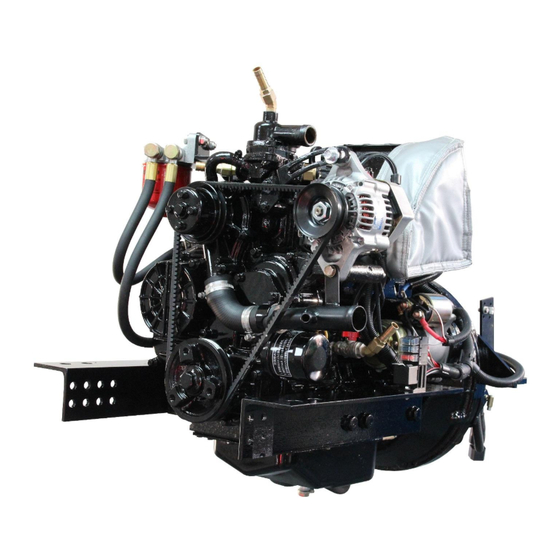
1. Shire 15 15 Canal Boat Description* Single Thermostat Housing 50 Amp 12 Volt Alternator Dry Exhaust Oil Filter Figure 2: Shire 15 15 CB Left Side (Viewed from front) Description* Air Filter Gearbox Engine Sump Pump Engine Fuel Filter... -
Page 16: Shire 15 20 Canal Boat
2. Shire 15 20 Canal Boat Description* Single Thermostat Housing 50 Amp 12 Volt Alternator Dry Exhaust Oil Filter Figure 4: Shire 15 20 CB Left Side (Viewed from front) Description* Air Filter Gearbox Engine Sump Pump Engine Fuel Filter Figure 5: Shire 15 20 CB Right Side (Viewed from rear) *Note: There are a number of optional extras that may be fitted to an engine that are not shown here. -
Page 17: Shire 15 15 River Boat
3. Shire 15 15 River Boat Description* Seawater Pump 50 Amp 12 Volt Alternator Oil Filter Water Cooled Exhaust Figure 6: Shire 15 15 RB Left Side (Viewed from front) Description* Air Filter Gearbox Engine Sump Pump Engine Fuel Filter Figure 7: Shire 15 15 RB Right Side (Viewed from rear) *Note: There are a number of optional extras that may be fitted to an engine that are not shown here. -
Page 18: Shire 15 20 River Boat
4. Shire 15 20 River Boat Description* Seawater Pump 50 Amp 12 Volt Alternator Oil Filter Water Cooled Exhaust Figure 8: Shire 15 20 RB Left Side (Viewed from front) Description* Air Filter Gearbox Engine Sump Pump Engine Fuel Filter Figure 9: Shire 15 20 RB Right Side (Viewed from rear) *Note: There are a number of optional extras that may be fitted to an engine that are not shown here. -
Page 19: Shire 15 15 Work Boat
5. Shire 15 15 Work Boat Description* Coolant Heat Exchanger 50 Amp 12 Volt Alternator Seawater Pump Dry Exhaust Oil Filter Figure 10: Shire 15 15 WB Left Side (Viewed from front) Description* Air Filter Gearbox Engine Sump Pump Engine Fuel Filter Figure 11: Shire 15 15 WB Right Side (Viewed from rear) *Note: There are a number of optional extras that may be fitted to an engine that are not shown here. -
Page 20: Shire 15 20 Work Boat
6. Shire 15 20 Work Boat Description* Coolant Heat Exchanger 50 Amp 12 Volt Alternator Seawater Pump Dry Exhaust Oil Filter Figure 12: Shire 15 20 WB Left Side (Viewed from front) Description* Air Filter Gearbox Engine Sump Pump Engine Fuel Filter Figure 13: Shire 15 20 WB Right Side (Viewed from rear) *Note: There are a number of optional extras that may be fitted to an engine that are not shown here. -
Page 21: Section 4 - Control Panel
SECTION 4 – Control Panel 1. Basic Control Panel Description Water Temperature Warning Light Oil Pressure Warning Light 50A Alternator Charge Warning Light Glow Plug Light Key Flap and Ignition Switch Figure 14: Basic Control Panel 12 Engine Stop 2. Standard Control Panel Description Tachometer Gauge Hour Meter... -
Page 22: Deluxe Control Panel
3. Deluxe Control Panel Description Tachometer Gauge Hour Meter Water Temperature Warning Light Oil Pressure Warning Light 50A Alternator Charge Warning Light 70A Alternator Charge Warning Light Glow Plug Light Key Flap and Ignition Switch Figure 16: Deluxe Control Panel 50A Alternator Output Gauge 10 Oil Pressure Gauge 11 Water Temperature Gauge... - Page 23 The water temperature warning light will only come on for a brief period of time when the ignition is first turned on as a bulb check. It will then only illuminate in the case of the engine coolant temperature exceeding the maximum safety level. ...
- Page 24 Description Procedure for Warning Light Tachometer Gauge Hour Meter Reduce the engine revs and stop the engine within one or two minutes. Check the coolant level (refer to 8. Cooling System of SECTION 7 - SERVICE PROCEDURE). If the coolant level is incorrect, fill it to the correct level (refer to 8.
-
Page 25: Overall Dimensions Of The Basic Control Panel
6. Overall Dimensions of the Basic Control Panel (All Dimensions are in mm) Figure 17: Basic Control Panel Dimensions 7. Overall Dimensions of the Standard Control Panel (All Dimensions are in mm) Figure 18: Standard Control Panel Dimensions RDG603A13 – Issue 19 Page 25 of 97... -
Page 26: Overall Dimensions Of The Deluxe Control Panel
8. Overall Dimensions of the Deluxe Control Panel (All Dimensions are in mm) Figure 19: Deluxe Control Panel Dimensions RDG603A13 – Issue 19 Page 26 of 97... -
Page 27: Section 5 - Installation
SECTION 5 – Installation NOTICE: REFER TO THE SHIRE MANUAL PRIOR TO INSTALLING THE ENGINE. 1. Ventilation All internal combustion engines radiate heat and require cool, clean air to aid complete combustion. Please Ensure that adequate engine room ventilation is provided, by fitting at least two vents of an aperture of not less than 10,000mm2 each (16in An allowance must be made for any grills, louvres or bends placed in the airflows and generally an increase of 25% in area is sufficient to overcome any... -
Page 28: Engine Cooling Water Connections
Figure 20: Skin Tank Flow Diagram Recommended Skin Tank Size Suggested Skin tank Suggested Engine Length mm surface area m Height mm 0.75 1000 0.75 1250 Skin tank size must be increased by up to approx 10% or a separate skin tank installed to cool the hydraulic oil, if a hydraulic bow thruster is used. -
Page 29: Pressurised Water Header Tank
following table. A.S.A.P Supplies Part Number Size of Hose (mm) 206428 28mm A.S.A.P. Supplies LTD can be contacted by: Telephone +44 1502 716993 Internet www.asap-supplies.com Please be aware that other suppliers are available. For River Boats & Workboats: Seawater inlet hose size: 19mm (¾”) ... -
Page 30: Shaft Connection And Propeller Selection
Connections on Engine Connections on Header Tank Shire 15/20 Canal and Work Boat Figure 21: Canal Boat / Work Boat Header Tank Connections 7. Shaft Connection and Propeller Selection Some type of flexible coupling must be used to connect the gearbox output flange to the propeller shaft flange. - Page 31 Figure 22: Correct Anti-Vibration Mount Installation RDG603A13 – Issue 19 Page 31 of 97...
- Page 32 Figure 23: Correct Anti-Vibration Mount Installation Description Normal mounting position Alternative mounting position if engine compartment space is restricted Figure 24: Anti-Vibration Mount Installation Points RDG603A13 – Issue 19 Page 32 of 97...
-
Page 33: Engine Alignment
9. Engine Alignment The gearbox output shaft flange and propeller shaft input flange must be almost perfectly aligned. A maximum of 0.05mm (0.002”) misalignment in any plane is acceptable. Ensure alignment is rechecked after the first 4 hours of running, after the first month and thereafter annually. -
Page 34: Electrics
11. Electrics CAUTION Do not attach any part, hose or cable to the engine wiring harness. There is a warning label attached to the harness to remind you of this. Connect the wiring extension harness multi plug to the panel plug and the other end to the engine. -
Page 35: Fuel
NOTICE: ENGINE OIL WITH A HIGHER API CLASS THAN CD IS UNSUITABLE FOR CANAL BOAT OPERATION AND WILL CAUSE ENGINE DAMAGE IF USED. All Shire engines are supplied fully run in. Check oil levels in engine and gearbox before starting ... -
Page 36: Coolant
15. Coolant WARNING: SCALD HAZARD! NEVER REMOVE THE COOLANT BOTTLE CAP IF THE ENGINE IS HOT. STEAM AND HOT COOLANT WILL SPURT OUT AND CAUSE INJURY. TIGHTEN THE CAP SECURELY AFTER BEING REMOVED. STEAM CAN SPURT OUT DURING ENGINE OPERATION IF THE CAP IS LOOSE. WARNING: BURN HAZARD! WAIT UNTIL THE ENGINE COOLS BEFORE YOU DRAIN THE ENGINE COOLANT. -
Page 37: Calorifier
air bubbles may be expelled. Top up the system as necessary. Riverboats with Water Cooled Manifold: Remove filler cap on top of water cooled exhaust manifold and fill cooling system through here. Run engine at idle for a few minutes with cap removed to ensure air is removed and allow a 13mm (1/2”) air gap in top of manifold to allow for expansion. -
Page 38: Control Cables
Inlet Outlet Figure 28: Position of Calorifiers on a Work Boat For River Boats: The calorifiers are positioned as per (Figure 29) Inlet Outlet Figure 29: Position of Calorifiers on a River Boat The temperature of coolant flowing to the calorifier from the engine can be between 85 and 90C. -
Page 39: Domestic Battery Bank
18. Domestic Battery Bank DANGER: EXPLOSION HAZARD! NEVER SHORT OUT THE BATTERY TERMINALS, INCLUDING WHEN CHECKING THE REMAINING BATTERY CHARGE THIS WILL RESULT IN A SPARK AND MAY CAUSE AN EXPLOSION OR FIRE. WARNING: BURN HAZARD! BATTERIES CONTAIN SULPHURIC ACID. NEVER ALLOW BATTERY FLUID TO COME IN CONTACT WITH SKIN, EYES OR CLOTHING. -
Page 40: Control Panel
(see below table). This must be set to the alternator with blue and black wire connected to it. Confirm settings to tacho meter reader. An optical tachometer is required to check the reading. Barrus Alternator (Amps) Barrus Tacho reading 10.50 – 11.00 15.00... -
Page 41: Exhaust System (Canal Boat)
20. Exhaust System (Canal Boat) WARNING: EXHAUST HAZARD! NEVER OPERATE ENGINE WITHOUT PROPER VENTILATION. NEVER BLOCK VENTS OR OTHER MEANS OF VENTILATION. ALL COMBUSTION ENGINES CREATE CARBON MONOXIDE GAS DURING OPERATION. ACCUMULATION OF THIS GAS COULD CAUSE ILLNESS OR EVEN DEATH. The exhaust outlet size on the engine is 1½”... -
Page 42: Exhaust System (Work Boat / River Boat)
The correct installation of the lift silencer is vital to safety, and to avoid back flooding of the engine. Figure 31 shows how to install the lift silencer correctly (Note: Halyard (M&I) Limited have given Barrus permission to use the diagram). Figure 31: Correct Installation of the Lift Silencer 1. - Page 43 Barrus recommend that Halyard (M&I) Limited are used for the Lift Silencer, Siphon Break and other components.
-
Page 44: Hydraulic Drive Transmissions
Siphon Breaker Fitting Instructions 1. The unit must be positioned upright, well above waterline. The height above waterline will vary from vessel to vessel but will be between 150mm and 2 metres. Please seek guidance on this if you are unsure, or if you are not familiar with the correct way to incorporate a siphon breaker into your particular exhaust system. - Page 45 No additional restriction to engine coolant flow is present. For Canal Boats: Skin tanks will also need to be increased by up to approx. 10% to dissipate the additional heat generated, when a hydraulic drive system or hydraulic bow thruster is used. An additional separate skin tank of suitable capacity with separate water circulating pump will need to be fitted for a hydraulic drive transmission Hydraulic oil coolers should be installed after the engine, not before.
-
Page 46: Installation Check List
23. Installation Check List Please tick box Engine alignment correct, clearance all round, check propeller turns by hand (Ensure ignition is off battery and battery master switch is off) Anti-Vibration mounts correct height, spacers if necessary. Make sure all nuts are tight Exhaust system as specified Battery leads are of correct size, tightened and start battery is charged Check tension of alternator belts &... -
Page 47: Section 6 - Operation
SECTION 6 – Operation NOTICE: REFER TO THE SHIRE MANUAL PRIOR TO STARTING THE ENGINE. 1. Starting the engine for the first time Remove ignition key. Ensure all oil and coolant levels are checked. Ensure both the engine and domestic batteries are connected. Both battery master switches must be turned on. -
Page 48: Stopping Procedure
Stop engine immediately if any abnormal noises are detected. Visually check the engine for oil, fuel and coolant leaks (after initial start-up and at regular intervals). Note: The engine must be stopped and ignition key removed to carry out this check. 3. -
Page 49: Diesel Fuel Additive
All Shire engines run on diesel fuel. DO NOT USE BIODIESEL Please note that when the vessel is to be left for any period of time, the fuel tank should be left full to eliminate the build-up of condensation and formation of water in the fuel tank. -
Page 50: Section 7 - Service Procedure
SECTION 7 – Service Procedure NOTICE: REFER TO THE SHIRE MANUAL PRIOR TO CARRYING OUT ANY SERVICE OR MAINTENANCE WORK. WARNING: PRIOR TO CARRYING OUT ANY SERVICE OR MAINTENANCE WORK MAKE SURE THE RELEVANT PERSONAL PROTECTION EQUIPMENT IS WORN. 1. Engine Oil and Filter Change WARNING: BURN HAZARD! WAIT UNTIL THE ENGINE COOLS SLIGHTLY BEFORE YOU DRAIN THE ENGINE OIL. -
Page 51: Air Filter Check And Change
2. Air Filter Check and Change Release the three spring clips. Pull off the end cover to reveal the filter element. The element simply pulls out. To fit the new element, slide the open end of the filter element into the main body. Gently push the element until fully seated. -
Page 52: Disposal Of Oil And Related Items
Gearbox Model Location of Dipstick / Filler Plug / Drain Plug Dipstick Filler Plug PRM 60 Level dipstick Magnetic Drain Plug (viewed & Filler Plug from underneath) PRM 80/90 Level dipstick PRM 150 & Filler Plug Figure 32: Location of Dipstick / Filler Plug / Drain Plug on Gearbox 4. -
Page 53: Fuel Filter Drain - Shire 15 15/20
Do not allow oil or contaminated parts to enter the inland water way system. 5. Fuel Filter Drain – Shire 15 15/20 WARNING: DIESEL FUEL IS FLAMMABLE AND EXPLOSIVE UNDER CERTAIN CONDITIONS. WARNING: DIESEL FUEL IS HARMFUL TO SKIN. MAKE SURE THE RELEVANT PERSONAL PROTECTION EQUIPMENT IS WORN. -
Page 54: Fuel Filter Change
Drain Screw Figure 33: Fuel Filter Drain Screw 6. Fuel Filter Change DANGER: DIESEL FUEL IS FLAMMABLE AND EXPLOSIVE UNDER CERTAIN CONDITIONS. WARNING: DIESEL FUEL IS HARMFUL TO SKIN. MAKE SURE THE RELEVANT PERSONAL PROTECTION EQUIPMENT IS WORN. Ensure the fuel tank is at least ¾ full prior to undertaking this procedure. ... -
Page 55: Fuel System Bleeding
7. Fuel System Bleeding DANGER: DIESEL FUEL IS FLAMMABLE AND EXPLOSIVE UNDER CERTAIN CONDITIONS. WARNING: DIESEL FUEL IS HARMFUL TO SKIN. MAKE SURE THE RELEVANT PERSONAL PROTECTION EQUIPMENT IS WORN. Ensure the fuel tank is at least ¾ full prior to undertaking this procedure. ... -
Page 56: Belt Adjustment
WARNING: BURN HAZARD! WAIT UNTIL THE ENGINE COOLS BEFORE YOU DRAIN THE ENGINE COOLANT. HOT ENGINE COOLANT MAY SPLASH AND BURN YOU. For All Models To check the coolant level, ensure that the engine has been shut down for at least half an hour. -
Page 57: Belt Maintenance
using hard finger pressure, the belt needs re-tensioning. Loosen the upper adjuster on the alternator. Loosen the lower mounting pivot nut and bolt. Pull out either using hand pressure, or a small plastic/wooden lever. Pull the alternator away from the engine to tighten the belt. ... -
Page 58: Belt Replacement
11. Belt Replacement WARNING: SEVERE HAZARD! KEEP HANDS AND OTHER BODY PARTS AWAY FROM MOVING/ROTATING PARTS. WEAR TIGHT FITTING CLOTHING AND KEEP YOUR HAIR SHORT OR TIE BACK. REMOVE ALL JEWELLERY BEFORE COMMENCING WORK. CHECK BEFORE STARTING THE ENGINE THAT ANY TOOLS OR RAGS USED DURING MAINTENANCE HAVE BEEN REMOVED FROM THE AREA. -
Page 59: Sacrificial Anode Change
connectors. Periodically squirt a lubricant into the key switch slot when the key has been removed (see Section 8 – Service Schedule). A lubricant such as WD40 – with silicon, would be suitable. Other lubricants are available. Then with the battery master switch turned off, operate the key switch a couple of times. -
Page 60: Raw Water Pump Impellor Change (Work Boat & River Boat)
Figure 35: River Boat Anode Location 14. Raw Water Pump Impellor Change (Work Boat & River Boat) The pump is located on the front of the engine. Remove the pump cover plate. Remove the pump impeller (special tools are available from chandleries to assist with this task). -
Page 61: Winterization Of Seawater Cooling System (Work Boat & River Boat)
For River Boats When the engine is cold, drain the water from the engine block. Remove the plug from the engine block by the starter motor. Drain water from the heat exchanger. The drain plug is in the bottom of the heat exchanger / water cooled manifold. -
Page 62: Section 8 - Service Schedule
SECTION 8 – Service Schedule NOTICE: REFER TO THE SHIRE MANUAL PRIOR TO CARRYING OUT ANY SERVICE OR MAINTENANCE WORK. WARNING: PRIOR TO CARRYING OUT ANY SERVICE OR MAINTENANCE WORK MAKE SURE THE RELEVANT PERSONAL PROTECTION EQUIPMENT IS WORN. 1. Specifications and Capacities Specification of Coolants and Lubricants to use: Component Lubricant... -
Page 63: Service Intervals
2. Service Intervals Check Change Notes Every 150 Hours Engine Oil & Filter Daily (Level) First change after 25 hours OR 12 Months* Weekly Every 300 Hours Gearbox Oil First change after 25 hours (Level) OR 12 Months* Coolant Level Daily (Level) Every 24 Months At first 50 hour... -
Page 64: Section 9 - Wiring Diagrams
SECTION 9 – Wiring Diagrams 1. Engine Wiring Diagram Shire 15 15/20 Figure 36: Shire 15 15/20 Wiring Diagram RDG603A13 – Issue 19 Page 64 of 97... -
Page 65: Basic Control Panel Wiring Diagram
2. Basic Control Panel Wiring Diagram Figure 37: Basic Control Panel Wiring Diagram RDG603A13 – Issue 19 Page 65 of 97... -
Page 66: Standard Control Panel Wiring Diagram
3. Standard Control Panel Wiring Diagram Figure 38: Standard Control Panel Wiring Diagram RDG603A13 – Issue 19 Page 66 of 97... -
Page 67: Deluxe Control Panel Wiring Diagram (Additional Option - Ss1551)
4. Deluxe Control Panel Wiring Diagram (Additional Option – SS1551) Figure 39: Deluxe Control Panel Wiring Diagram RDG603A13 – Issue 19 Page 67 of 97... -
Page 68: Section 10 - Technical Data
SECTION 10 – Technical Data 1. Engine Data Engine Model Shire 15 15 Shire 15 20 Type In Line, Water Cooled, 4 Stroke In Line, Water Cooled, 4 Stroke Combustion Chamber Swirl Chamber Swirl Chamber Aspiration Natural Natural Number of Cylinders Bore x Stroke 78 x 78.4mm 78 x 78.4mm... -
Page 69: Return Diesel System
2. Return Diesel System Maximum Fuel Temp 18.2°c Maximum Flow 0.6 Litre / Min (2650 rpm) Flow at Idle 0.3 Litre / Min 3. Dry Weight of Engine Data Dry Weight of Engine (Including Gearbox)* Model Dry Weight (kg) Shire 15 15 142kg Shire 15 20 160kg... -
Page 70: Section 11 - Dealer List
SECTION 11 – Dealer List Area Company Telephone Email Bluenine Marine 01189 406482 bluenine@marine7957.fsnet.co.uk Driveline Marine 0118 942 3877 tam@drivelinemarine.com BERKSHIRE Marcus Marine Engineering Ltd 07900890911 marcusmarine@icloud.com (Servicing, Repairs & Breakdowns only) CHESHIRE Nantwich Canal Centre 01270 625122 info@nantwichcc.com Black Dog Marine 01503 265898 blackdogmarine@googlemail.com Cellar Marine... - Page 71 JD Boat Services Ltd 01902 791811 jdboats@btinternet.com STAFFORDSHIRE Stone Boatbuilding Company 01785 812688 sales@stonebuilding.co.uk Streethay Wharf 01543 414770 pat@streethaywarf.freeserve.co.uk Barry Hawkins Narrowboats 01827 711762 boats@hawkinsyard.freeserve.co.uk Onboard Energy 02476 393333 sales@onboardenergy.com WARWICKSHIRE Springwood Haven Leisure Ltd 0845 4566572 enquiries@springwoodhaven.co.uk Valley Boat Services Ltd 07990528123 enquiries@valleycruises.co.uk WEST MIDLANDS...
-
Page 72: Section 12 - Shire Parts
SECTION 12 – Shire Parts Model 15/20 CB 15/20 WB 15/20 RB Fuel Filter RDG906A3 RDG906A3 RDG906A3 GB/T12732- GB/T12732- GB/T12732- 50A Alt Belt 2008 2008 2008 GB/T12732- GB/T12732- GB/T12732- 70A Alt Belt (Single Alt Engine) 2008 2008 2008 Air Filter Element 3011-T3-0004 3011-T3-0004 3011-T3-0004... - Page 73 Fuses & Relays: The electrical system is fitted with three or four blade type fuses: Engine Stop Control System Fuse 40amp RDG3246 Control Panel Supply Fuse 15amp RDG3245 Engine Start Control System Fuse 15amp RDG3245 Glow Plug Fuse 40amp RDG3246 Cold Start Relay RDG5279 Starter Relay...
-
Page 74: Section 13 - Declarations
Name of Engine Manufacturer: E.P.Barrus LTD Name of Authorised Representative: E.P.Barrus LTD Address: E.P.Barrus LTD, Launton Road, Bicester, Oxon, OX26 4UR, England Name of Notified Body for exhaust emission assessment: HPi Verification Services Ltd Address: The Manor House, Howbery Park... -
Page 75: Declaration Of Incorporation Of Partly Completed Machinery
2. Declaration of Incorporation of Partly Completed Machinery (Original declaration according to Directive 2006/42/EC, Annex II, part 1B) 1. The manufacturer: E. P. Barrus Limited Glen Way Launton Road Bicester OX26 4UR 2. Authorised Compiler of Mr. Graeme Aldridge Relevant Technical... - Page 76 ANNEX A The essential health and safety requirements for machinery can only be made compliant partly by Barrus. Therefore Barrus recommends to double-check the paragraphs from Annex 1 of the Directive 2006/42/EC mentioned below for compliance with the Directive for your particular machine.
- Page 77 For the fuel filter, fuel injection pump, fuel injection nozzles, high pressure fuel injection pipes and fuel hoses supplied and installed on the engine by Barrus. Any other fuel system parts connected to the engine to be made compliant by the boat builder/installer.
- Page 78 1.5.8 Noise 1.5.9 Vibrations 1.5.10 Radiation 1.5.11 External radiation 1.5.12 Laser radiation Not applicable 1.5.13 Emissions hazardous materials and substances Except for the exhaust, fuel, and cooling water system which needs to be properly connected by the boat builder or installer according to the Shire Manual. 1.5.14 Risk of being trapped in a machine...
-
Page 79: Section 14 - Lubricant Safety Data Sheets
SECTION 14 – Lubricant Safety Data Sheets 1. Ground Force 10W-40 SAFETY DATA SHEET Ground Force 10W-40 SECTION 1: Identification of the substance/mixture and of the company/undertaking 1.1. Product identifier Product name Ground Force 10W-40 Product number 7450 Internal identification GHS21580 REACH registration number n/a Mixture... - Page 80 SECTION 3: Composition/information on ingredients 3.2. Mixtures Distillates (petroleum) solvent-dewaxed heavy paraffinic 30-60% CAS-No.: 64742-65-0 EC No.: 265-169-7 REACH registration number: 01- 2119471299-27-XXXX A petroleum product. DMSO extract < 3 % weight ( IP 346 ) Classification Classification (67/548/EEC or 1999/45/EC) Not classified.
- Page 81 SECTION 5: Firefighting measures 5.1. Extinguishing media Suitable extinguishing media Extinguish with foam, carbon dioxide, dry powder or water fog. Unsuitable extinguishing Do not use water jet as an extinguisher, as this will spread the fire. Media 5.2. Special hazards arising from the substance or mixture Specific hazards Heat from fire could result in drums bursting Hazardous combustion...
- Page 82 SECTION 8: Exposure Controls/personal protection 8.1. Control parameters Occupational exposure limits Distillates (petroleum) solvent-dewaxed heavy paraffinic Long-term exposure limit (8-hour TWA): ACGIH 5 mg/m³ Short-term exposure limit (15-minute): ACGIH 10 mg/m³ Distillates,hydrotreated heavy paraffinic Long-term exposure limit (8-hour TWA): ACGIH Short-term exposure limit (15-minute): ACGIH 10 mg/m³...
- Page 83 8.2. Exposure controls Protective equipment Appropriate engineering Provide adequate general and local exhaust ventilation. Observe any occupational exposure controls limits for the product or ingredients. Eye/face protection Eyewear complying with an approved standard should be worn if a risk assessment indicates eye contact is possible.
- Page 84 Decomposition Temperature Not determined. Viscosity 89.4 cSt @ 40°C Explosive properties Not considered to be explosive. Explosive under the influence Not considered to be explosive. of a flame Oxidising properties The mixture itself has not been tested but none of the ingredient substances meet the criteria for classification as oxidising.
- Page 85 Carcinogenicity Carcinogenicity This product contains mineral oils which are considered to be severly refined and not considered to be carcinogenic under IARC. All of the oils in this product have been demonstrated to contain less than 3% extractables by the IP346 test Reproductive toxicity Reproductive toxicity - fertility No data available to suggest the product will cause reproductive toxicity.
- Page 86 12.5. Results of PBT and vPvB assessment Results of PBT and vPvB This product does not contain any substances classified as PBT or vPvB. assessment 12.6. Other adverse effects Other adverse effects None known. SECTION 13: Disposal considerations 13.1. Waste treatment methods General information This material and its container must be disposed of as hazardous waste.
- Page 87 15.2. Chemical safety assessment No chemical safety assessment has been carried out. Inventories Canada - DSL/NDSL All the ingredients are listed or exempt. US - TSCA All the ingredients are listed or exempt. Australia - AICS All the ingredients are listed or exempt. Korea - KECI All the ingredients are listed or exempt.
-
Page 88: Liquimatic Super Atf
2. Liquimatic Super ATF SAFETY DATA SHEET Liquimatic Super ATF SECTION 1: Identification of the substance/mixture and of the company/undertaking 1.1. Product identifier Product name Liquimatic Super ATF Product number 7290 Internal identification GHS21439 REACH registration number n/a Mixture 1.2. Relevant identified uses of the substance or mixture and uses advised against Identified uses Transmission fluid Uses advised against... - Page 89 SECTION 3: Composition/information on ingredients 3.2. Mixtures Distillates (petroleum) solvent-dewaxed heavy paraffinic 60-100% CAS-No.: 64742-65-0 EC No.: 265-169-7 REACH registration number: 01- 2119471299-27-XXXX Classification Classification (67/548/EEC or 1999/45/EC) Asp. Tox. 1 - H304 Lubricating oil (petroleum) C20-C50,hydrotreated,neutral oil 10-30% based CAS number: 72623-87-1 EC number: 276-738-4 REACH registration number: 01-...
- Page 90 SECTION 5: Firefighting measures 5.1. Extinguishing media Suitable extinguishing media Extinguish with foam, carbon dioxide, dry powder or water fog. Unsuitable extinguishing Do not use water jet as an extinguisher, as this will spread the fire. Media 5.2. Special hazards arising from the substance or mixture Specific hazards Heat from fire could result in drums bursting Hazardous combustion...
- Page 91 SECTION 8: Exposure Controls/personal protection 8.1. Control parameters Occupational exposure limits Distillates (petroleum), solvent-dewaxed heavy paraffinic Long-term exposure limit (8-hour TWA): ACGIH 5 mg/m³ Short-term exposure limit (15-minute): ACGIH 10 mg/m³ Lubricating oil (petroleum) C20-C50,hydrotreated,neutral oil based Long-term exposure limit (8-hour TWA): ACGIH 5 mg/m³...
- Page 92 Not applicable. Melting point -40°C Pour point Initial boiling point and range >320°C @ 101.3 kPa Flash point 196°C PMCC (Pensky-Martens closed cup). Evaporation rate Not relevant. Upper/lower flammability or Not known. explosive limits Other flammability Product is not flammable but on excessive heating may become combustible. Vapour pressure <0.1 kPa @ 20°C Vapour density...
- Page 93 SECTION 11: Toxicological information 11.1. Information on toxicological effects Acute toxicity - oral Acute toxicity oral (LD₅₀ 2,000.0 mg/kg) Species Notes (oral LD₅₀) Not expected to be highly toxic based on information of ingredients. Based on available data the classification criteria are not met. Acute toxicity - dermal Acute toxicity dermal (LD₅₀...
- Page 94 SECTION 12: Ecological Information Ecotoxicity Based on available data the classification criteria are not met. Not regarded as dangerous for the environment. 12.1. Toxicity Toxicity Based on available data the classification criteria are not met. Not considered toxic to fish. Acute toxicity –...
- Page 95 14.3. Transport hazard class(es) No transport warning sign required. 14.4. Packing group Not applicable. 14.5. Environmental hazards Environmentally hazardous substance/marine pollutant 14.6. Special precautions for user Not applicable. 14.7. Transport in bulk according to Annex II of MARPOL73/78 and the IBC Code Transport in bulk according to Not applicable.
- Page 96 SECTION 16: Other information Revision comments NOTE: Lines within the margin indicate significant changes from the previous revision. Issued by Regulatory Affairs Revision date 26/10/2015 Revision SDS number 21439 Hazard statements in full H304 May be fatal if swallowed and enters airways. H319 Causes serious eye irritation.
-
Page 97: Section 15 - Shire Service Record Card
SECTION 15 – Shire Service Record Card SERVICE RECORD CARD ……………………………………………………………………… Model: ……………………………………………………………….. Engine No: Carried out by E.P.Barrus Boat Builder Stamp: Print Name: Commission of Boat and Hand Over to Customer. (Refer to the Installation Check List Page in this Actual Hours: Manual).
Need help?
Do you have a question about the Shire 15 15 CB and is the answer not in the manual?
Questions and answers