
Related Manuals for Barrus Shire 65


Summary of Contents for Barrus Shire 65
- Page 1 ORIGINAL INSTRUCTION CANAL ENGINE MANUAL For the following engine models: Shire 60 Shire 65 RDG603A31 - Issue 4...
- Page 2 SAFETY E.P. Barrus is concerned for your safety. We use safety statements throughout the manual to call your attention to the potential hazards associated with the operation of your Shire engine. Follow the precautions listed throughout the manual before operation, during operation and during servicing/maintenance procedures for your safety, the safety of others and to protect the performance of your engine.
- Page 3 Engine Details Engine Serial Number: Please enter your engine serial number in the space provided above. Please quote the engine identification number during any enquiry or when ordering spare parts. Information about the engine serial number and its location on the engine can be found in SECTION 2 of the manual.
-
Page 4: Rdg603A31 - Issue
A TRANSFER OF TITLE OCCURS, IT MUST ALWAYS BE HANDED OVER TO THE NEW OWNER. Thank you for purchasing this Shire Canal Boat Marine Engine from E.P.Barrus. This manual has been compiled to help you to operate your engine and its associated parts with safety and pleasure. - Page 5 Routine maintenance outlined in the Owner’s Manual must be performed using genuine parts in order to maintain warranty coverage. If the customer performs maintenance, Barrus reserves the right to make future warranty coverage possible only with proof of proper maintenance.
- Page 6 the repairs carried out are not covered by the warranty, the purchaser shall pay for all related labour and material, and any other expenses associated with that service. WHAT IS NOT COVERED This limited warranty does not cover routine maintenance items, adjustments, normal wear and tear, damage caused by abnormal use, operation of the product in a manner inconsistent with the recommended operation/duty cycle section of the Owner’s Manual, accident, submersion, improper installation (proper installation specification and techniques are set...
-
Page 7: Table Of Contents
Launching and Lifting Boats..................12 Batteries........................12 SECTION 2 – Engine Identification...................14 SECTION 3 – Component Identification ................15 Shire 60 ........................15 Shire 65 ........................16 SECTION 4 – Control Panel ....................17 Standard Control Panel....................17 Deluxe Control Panel ....................17 Control Panel Overview .....................18 Warning Light Procedure ...................18 Overall Dimensions of the Standard Control Panel ............20... - Page 8 Engine Alignment .......................27 Engine Inclination ......................28 Electrics ........................29 Electrical Options .......................29 Engine Oil ........................30 Fuel ..........................30 Coolant ........................31 Control Cables ......................32 Domestic Battery Bank ....................32 Control Panel ......................33 Exhaust System ......................34 Hydraulic Drive Transmissions ..................35 Centa Coupling CF-M-160 (RDG2779) ..............36 PRM 280DP Gearbox with Power Take Off (Optional Extra) ........37 Installation Check List ....................38 SECTION 6 –...
- Page 9 Primary Fuel Filter Drain – Shire 60 & 65 ..............44 Primary and Secondary Fuel Filter Change ...............46 Fuel System Bleeding ....................46 Cooling System ......................48 Belt Adjustment ......................48 Belt Maintenance .......................49 Belt Replacement ......................50 Control Panel Maintenance..................50 SECTION 8 – Service Schedule ..................52 Specifications and Capacities ..................52 Service Intervals ......................53 SECTION 9 –...
- Page 10 SECTION 14 – Lubricant Safety Data Sheets ..............71 Ground Force 10W-40 ....................71 Torq-Gard Supreme 15W-40 ..................80 SECTION 15 – Shire Service Record Card ...............88 RDG603A31- Issue 4 Page 10 of 88...
-
Page 11: Section 1 - Safety Precautions
SECTION 1 – Safety Precautions 1. General NOTICE: NEVER PERMIT ANYONE TO OPERATE THE ENGINE WITHOUT PROPER TRAINING. It is the responsibility of the installer/operator to ensure that the finished installation complies with CE Marking, the relevant Health & Safety requirements and the recreational craft directive before commissioning. -
Page 12: Exhaust System
The engine and its accessories are not intended to be put into operation until they are integrated into the boat as a whole. No person should be in the engine compartment and the engine cover or deck hatches should be closed whilst the engine is running. 4. - Page 13 WARNING: BURN HAZARD! BATTERIES CONTAIN SULPHURIC ACID. NEVER ALLOW BATTERY FLUID TO COME IN CONTACT WITH SKIN, EYES OR CLOTHING. SEVERE BURNS COULD RESULT. MAKE SURE THE CORRECT PERSONAL PROTECTION EQUIPMENT IS WORN. Batteries can produce explosive gases; keep sparks and flames away from the battery. NO SMOKING ...
-
Page 14: Section 2 - Engine Identification
SECTION 2 – Engine Identification The engine serial number can be found engraved into the brass plate on the top of the engine rocker cover and stamped to the crankcase next to the starter motor. The Canal Boat Engines (CB) do not have identification initials on the engraved plate. An example of the engine identification plate is shown below (Figure 1): Description Engine Model... -
Page 15: Section 3 - Component Identification
SECTION 3 – Component Identification 1. Shire 60 Description* Single Thermostat Housing 40 Amp 12 Volt Alternator 150 Amp 12 Volt Alternator Dry Exhaust Outlet Figure 2: Shire 60 Left Side (Viewed from front) Description* Air Filter Gearbox Oil Filter Primary and Secondary Fuel Filters Engine Sump Pump... -
Page 16: Shire 65
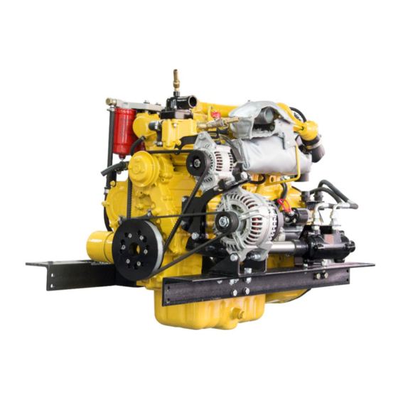
2. Shire 65 Description* Single Thermostat Housing 50 Amp 12 Volt Alternator 150 Amp 12 Volt Alternator Dry Exhaust Outlet Figure 4: Shire 65 Left Side (Viewed from front) Description* Primary and Secondary Fuel Filters Air Filter Gearbox Oil Filter... -
Page 17: Section 4 - Control Panel
SECTION 4 – Control Panel 1. Standard Control Panel Description 1 Tachometer Gauge 2 Hour Meter 3 Water Temperature Warning Light 4 Oil Pressure Warning Light 40A Alternator Charge Warning Light 150/240A Alternator Charge Warning Light 7 Glow Plug Light 8 Key Flap and Ignition Switch Figure 6: Standard Control Panel 2. -
Page 18: Control Panel Overview
3. Control Panel Overview All Shire engines are supplied with a control panel. Depending on the model of Shire engine, the control panel will either be a standard control panel or a deluxe control panel. The following table shows which panel comes with each type of engine as standard. - Page 19 Description Procedure for Warning Light Tachometer Gauge Hour Meter Reduce the engine revs and stop the engine within one or two minutes. Check the coolant level (refer to 8. Cooling System of SECTION 7 - SERVICE PROCEDURE). If the coolant level is incorrect, fill it to the correct level (refer to 8.
-
Page 20: Overall Dimensions Of The Standard Control Panel
5. Overall Dimensions of the Standard Control Panel (All Dimensions are in mm) Figure 8: Standard Control Panel Dimensions 6. Overall Dimensions of the Deluxe Control Panel (All Dimensions are in mm) Figure 9: Deluxe Control Panel Dimensions RDG603A31- Issue 4 Page 20 of 88... -
Page 21: Section 5 - Installation
SECTION 5 – Installation NOTICE: REFER TO THE SHIRE MANUAL PRIOR TO INSTALLING THE ENGINE. 1. Ventilation All internal combustion engines radiate heat and require cool, clean air to aid complete combustion. Please Ensure that adequate engine room ventilation is provided, by fitting at least two vents of an aperture of not less than 15,000mm each (24in An allowance must be made for any grills, louvres or bends placed in the... -
Page 22: Engine Cooling Water Inlet And Outlet Hose Connections
Figure 10: Skin Tank Flow Diagram Recommended Skin Tank Size Suggested Skin tank Suggested Engine Length mm surface area m Height mm 1.35 1800 1.46 1950 If a hydraulic bow thruster is used, the skin tank size must be increased by up to approx 10% or a separate skin tank installed to cool the hydraulic oil. -
Page 23: Pressurised Water Header Tank
A.S.A.P Supplies Part Number Size of Hose (mm) 206435 35mm A.S.A.P. Supplies LTD can be contacted by: Telephone +44 1502 716993 Internet www.asap-supplies.com Please be aware that other suppliers are available. 6. Pressurised Water Header Tank WARNING: SCALD HAZARD! NEVER REMOVE THE HEADER TANK CAP IF THE ENGINE IS HOT. -
Page 24: Calorifier
Connections on Engine Connections on Header Tank Shire 60 & 65 Figure 11: Header Tank Connections 7. Calorifier The temperature of coolant flowing to the calorifier from the engine can be between 85 and 90°C. A blender valve must be incorporated in the calorifier / hot water system outlet to lower the hot water temperature for domestic use. -
Page 25: Shaft Connection And Propeller Selection
Connections on Engine Outlet Shire 60, 65 Inlet Figure 12: Calorifier Connections 8. Shaft Connection and Propeller Selection Some type of flexible coupling must be used to connect the gearbox output flange to the propeller shaft flange. Please note, underperforming engines will not be covered under warranty if the cause of the poor performance is found to be the use of an inappropriate propeller. - Page 26 alternative holes and the front of the rail cut off – leaving 50mm of material to retain strength (measuring from the centre of the mount hole to the front end of the rail). Note: This procedure is only possible on non 230V Power system engines, and may result in a very slight increase in vibration.
-
Page 27: Engine Alignment
Figure 14: Correct Anti-Vibration Mount Installation Description Normal mounting position Alternative mounting position if engine compartment space is restricted Figure 15: Anti-Vibration Mount Installation Points 10. Engine Alignment The gearbox output shaft flange and propeller shaft input flange must be almost RDG603A31- Issue 4 Page 27 of 88... -
Page 28: Engine Inclination
perfectly aligned. A maximum of 0.05mm (0.002”) misalignment in any plane is acceptable. Ensure alignment is recheck after the first 4 hours of running, after the first month and thereafter annually. If the engine is out of alignment it will result in excessive vibration and possible damage to the stern tube and propeller shaft. -
Page 29: Electrics
12. Electrics CAUTION Do not attach any part, hose or cable to the engine wiring harness. There is a warning label attached to the harness to remind you of this. Connect the wiring extension harness multi plug to the panel plug and the other end to the engine. -
Page 30: Engine Oil
If the engine is fitted with the optional 230V Power System, refer to the manual supplied with it for correct wiring, control box installation and operation. The Shire range can be supplied with other optional additional 12V or 24V alternators. This will be supplied fitted but not wired. -
Page 31: Coolant
A separate water trap must be fitted to all engine installations. The Shire 60 & 65 engines are supplied with an additional fuel pre-filter water trap as standard. Connect fuel feed return hoses from engine to main supply and return lines to main fuel tank, ensuring they are connected the correct way around. -
Page 32: Control Cables
Prepare coolant mix of 50% clean tap water and 50% antifreeze. Open the calorifier taps (if fitted) to fill the calorifier system and displace air. To fill the cooling system for the first time, fill the boat skin via the inlet hose connection or filler plug if fitted. -
Page 33: Control Panel
recommended size will not be covered by warranty. Higher output additional alternators, or 230V power kits are available: if larger battery banks are required discuss your individual power requirements with the boat builder or engine supplier. The maximum domestic battery bank is calculated using the following: Live aboard, three times domestic alternator, maximum output current. -
Page 34: Exhaust System
(see below table). This must be set to the alternator with blue and black wire connected to it. Confirm settings to tacho meter reader. An optical tachometer is required to check the reading. Barrus Alternator (Amps) Barrus Tacho reading 10.50 – 11.00 19.50 – 20.00 22.00... -
Page 35: Hydraulic Drive Transmissions
Part Description Part Number Exhaust Coupling 1½” x 1½” BSP RDG1916 Exhaust Silencer DSA-38 RDG1911 Flexible Exhaust Hose (18”) RDG1879 Blanket 18” Flexy Exhaust RDG2477 Hospital Silencer 1½“ BSP RDG6536 Make sure the exhaust increases then decreases in height as shown in (Figure 17). Figure 17: Correct Exhaust Installation 21. -
Page 36: Centa Coupling Cf-M-160 (Rdg2779)
22. Centa Coupling CF-M-160 (RDG2779) Centa have given Barrus permission to use the following instruction on how to fit the coupling: When assembling the coupling all the bolts and nuts must be tightened to the correct torque using a torque wrench. -
Page 37: Prm 280Dp Gearbox With Power Take Off (Optional Extra)
The propeller-thrust (or propeller-pull in reverse drive) is safely transmitted via the coupling from the propeller shaft to the gearbox, but the design of the coupling is such that the rubber must be compressed when sailing in the forward direction. The coupling is not suitable for use with vee-drive gearboxes having outputs of the quill-shaft arrangement where the coupling would be subject to a pulling force when sailing forward. -
Page 38: Installation Check List
24. Installation Check List Please tick box Engine alignment correct, clearance all round, check propeller turns by hand (Ensure ignition is off battery and battery master switch is off) Anti-Vibration mounts correct height, spacers if necessary. Make sure all nuts are tight Exhaust system as specified Battery leads are of correct size, tightened and start battery is charged Check tension of alternator belts, wiring connected and belt alignment... -
Page 39: Section 6 - Operation
SECTION 6 – Operation NOTICE: REFER TO THE SHIRE MANUAL PRIOR TO STARTING THE ENGINE. 1. Starting the engine for the first time Remove ignition key. Ensure all oil and coolant levels are checked. Ensure both the engine and domestic batteries are connected. Both battery master switches must be turned on. -
Page 40: Stopping Procedure
3. Stopping Procedure Move speed control lever to idle position. Turn key to off position. 4. Full Load Running Running diesel engines near there rated output (maximum load) regularly will disperse accumulated carbon and condensation, enhancing engine life and reducing emissions. -
Page 41: Diesel Fuel Additive
6. Diesel Fuel Additive The use of diesel fuel additive is strongly recommended on Shire engines. The quality of the fuel available when cruising is often unknown. Also the fuel may have been in storage for long periods of time. The use of additives will ensure that your engine fuel injection system is in top condition which should result in many years of smooth reliable operation, without the cost and inconvenience of expensive breakdowns due to poor quality fuel. -
Page 42: Section 7 - Service Procedure
SECTION 7 – Service Procedure NOTICE: REFER TO THE MANUAL PRIOR TO CARRYING OUT ANY SERVICE OR MAINTENANCE WORK. WARNING: PRIOR TO CARRYING OUT ANY SERVICE OR MAINTENANCE WORK MAKE SURE THE RELEVANT PERSONAL PROTECTION EQUIPMENT IS WORN. 1. Engine Oil and Filter Change WARNING: BURN HAZARD! WAIT UNTIL THE ENGINE COOLS SLIGHTLY BEFORE YOU DRAIN THE ENGINE OIL. -
Page 43: Air Filter Check And Change
components of the engine. 2. Air Filter Check and Change Release the two spring clips. Pull off the end cover to reveal the filter element. The element simply pulls out. To fit the new element, slide the open end of the filter element into the main body. Gently push the element until fully seated. -
Page 44: Disposal Of Oil And Related Items
Gearbox Model Location of Dipstick / Filler Plug / Drain Plug Level dipstick PRM 150 & Filler Plug Level dipstick & Filler Plug PRM 280 Figure 18: Location of Dipstick / Filler Plug / Drain Plug on Gearbox 4. Disposal of Oil and Related Items NOTICE: ALWAYS BE ENVIRONMENTALLY RESPONSIBLE. - Page 45 WARNING: DIESEL FUEL IS HARMFUL TO SKIN. MAKE SURE THE RELEVANT PERSONAL PROTECTION EQUIPMENT IS WORN. Place a small drain bowl under the primary fuel filter / water trap. Loosen the drain screw located in the bottom of the fuel filter / water trap (Figure 19) ...
-
Page 46: Primary And Secondary Fuel Filter Change
6. Primary and Secondary Fuel Filter Change DANGER: DIESEL FUEL IS FLAMMABLE AND EXPLOSIVE UNDER CERTAIN CONDITIONS. WARNING: DIESEL FUEL IS HARMFUL TO SKIN. MAKE SURE THE RELEVANT PERSONAL PROTECTION EQUIPMENT IS WORN. Ensure the fuel tank is at least ¾ full prior to undertaking this procedure. ... - Page 47 WARNING: DIESEL FUEL IS HARMFUL TO SKIN. MAKE SURE THE RELEVANT PERSONAL PROTECTION EQUIPMENT IS WORN. Ensure the fuel tank is at least ¾ full prior to undertaking this procedure. Open the bleed screw on top of the engine fuel filter (Figure 20). ...
-
Page 48: Cooling System
8. Cooling System DANGER: SCALD HAZARD! NEVER REMOVE THE COOLANT PRESSURE CAP IF THE ENGINE IS HOT. STEAM AND HOT COOLANT WILL SPURT OUT AND SERIOUSLY BURN YOU. TIGHTEN THE CAP SECURELY AFTER BEING REMOVED. STEAM CAN SPURT OUT DURING ENGINE OPERATION IF THE CAP IS LOOSE. WARNING: BURN HAZARD! WAIT UNTIL THE ENGINE COOLS BEFORE YOU DRAIN THE ENGINE COOLANT. -
Page 49: Belt Maintenance
Depress the longest run of the drive belt to be checked. If the travel exceeds 15-20mm using hard finger pressure, the belt needs re-tensioning. Loosen the upper adjuster on the alternator. Loosen the lower mounting pivot nut and bolt. -
Page 50: Belt Replacement
11. Belt Replacement WARNING: SEVERE HAZARD! KEEP HANDS AND OTHER BODY PARTS AWAY FROM MOVING/ROTATING PARTS. WEAR TIGHT FITTING CLOTHING AND KEEP YOUR HAIR SHORT OR TIE BACK. REMOVE ALL JEWELLERY BEFORE COMMENCING WORK. CHECK BEFORE STARTING THE ENGINE THAT ANY TOOLS OR RAGS USED DURING MAINTENANCE HAVE BEEN REMOVED FROM THE AREA. - Page 51 Periodically squirt a lubricant into the key switch slot when the key has been removed (see Section 8 – Service Schedule). A lubricant such as WD40 – with silicon, would be suitable. Other lubricants are available. Then with the battery master switch turned off, operate the key switch a couple of times.
-
Page 52: Section 8 - Service Schedule
SECTION 8 – Service Schedule NOTICE: REFER TO THE SHIRE MANUAL PRIOR TO CARRYING OUT ANY SERVICE OR MAINTENANCE WORK. WARNING: PRIOR TO CARRYING OUT ANY SERVICE OR MAINTENANCE WORK MAKE SURE THE RELEVANT PERSONAL PROTECTION EQUIPMENT IS WORN. 1. Specifications and Capacities Specification of Coolants and Lubricants to use: Component Lubricant... -
Page 53: Service Intervals
2. Service Intervals Check Change Notes Every 350 Hours Engine Oil & Filter Daily (Level) First change after 50 hours OR 12 Months* Weekly Every 350 Hours Gearbox Oil First change after 25 hours (Level) OR 12 Months* Coolant Level Daily (Level) Every 24 Months At first 50 hour... -
Page 54: Section 9 - Wiring Diagrams
SECTION 9 – Wiring Diagrams 1. Engine Wiring Diagram Shire 60 & 65 Figure 21: Shire 60 & 65 Wiring Diagram RDG603A31- Issue 4 Page 54 of 88... -
Page 55: Shire 60 & 65 Cold Start Wiring Diagram
2. Shire 60 & 65 Cold Start Wiring Diagram Figure 22: Shire 60 & 65 Cold Start Wiring Diagram RDG603A31- Issue 4 Page 55 of 88... -
Page 56: Standard Control Panel Wiring Diagram
3. Standard Control Panel Wiring Diagram Figure 23: Standard Control Panel Wiring Diagram RDG603A31- Issue 4 Page 56 of 88... -
Page 57: Deluxe Control Panel Wiring Diagram
4. Deluxe Control Panel Wiring Diagram Figure 24: Deluxe Control Panel Wiring Diagram RDG603A31- Issue 4 Page 57 of 88... -
Page 58: Section 10 - Technical Data
Direct Injection Aspiration Turbocharged Number of Cylinders Bore x Stroke 87 x 103mm Displacement 2.449L Shire 60 Shire 65 Rated Output/Speed 44kW (60hp) at 48kW (65hp) at 2500rpm 2600rpm Low Idling 875 - 900 rpm High Idling 2700 ±25 rpm... -
Page 59: Dry Weight Of Engine Data
Model Dry Weight (kg) Shire 60 328kg Shire 65 332kg * The dry weights stated are for the standard engine in each model range. If a different gearbox or additional alternators are ordered the weight will change accordingly. 4. Torque Settings for Screws, Bolts and Nuts... -
Page 60: Cylinder Head Tightening Sequence
5. Cylinder Head Tightening Sequence Figure 25: Cylinder Head Tightening Sequence Tighten all the cylinder head bolts to 30Nm following the sequence shown in Figure Tighten all the cylinder head bolts to 50Nm following the sequence shown in Figure ... -
Page 61: Section 11 - Dealer List
SECTION 11 – Dealer List Area Company Telephone Email Bluenine Marine 01189 406482 info@blueninemarine.co.uk Driveline Marine 0118 942 3877 tam@drivelinemarine.com BERKSHIRE Marcus Marine Engineering Ltd 07900890911 Marcus@marcusmarine.co.uk (Servicing, Repairs & Breakdowns only) BRISTOL Advance Marine 01275 815910 phil@advancemarine.co.uk Midland Chandlers 01928 751 800 preston.brook@midlandchandlers.co.uk CHESHIRE... - Page 62 Crafted Boats Ltd 01527 876438 craftedboats@btconnect.com WORCESTERSHIRE Evesham Marina 01386 768500 info@eveshammarina.co.uk YORKSHIRE Rodley Boat Centre 01132 576132 rodleyboatcentre@msn.com MONMOUTHSHIRE Castle Narrowboats 01873 830001 info@castle.narrowboats.co.uk EIRE Southshore Marina & Diesel Ltd 028383 41010 info@southshoremarine.co.uk RDG603A31- Issue 4 Page 62 of 88...
-
Page 63: Section 12 - Shire Parts
SECTION 12 – Shire Parts Model Shire 60 Shire 65 Primary Fuel Filter RDG9188346 RDG9188346 Secondary Fuel Filter RDG9188345 RDG9188345 40A Alternator R300037010003 R300037010003 40A Alt Belt R300037010001 R300037010001 150A Alternator RDG20110201 RDG20110201 150A Alt Belt RDG2254 RDG2254 240A Alternator (Option) - Page 64 Fuses & Relays: The electrical system is fitted with four blade type fuses: Engine Stop Control System Fuse 40amp RDG3246 Control Panel Supply Fuse 15amp RDG3245 Engine Start Control System Fuse 15amp RDG3245 Glow Plug Fuse 40amp RDG3246 Cold Start Relay RDG5279 Starter Relay RDG1396...
-
Page 65: Section 13 - Declarations
2017042502 XX-2400-X Shire 65 Name of Engine Manufacturer and Authorised Representative: E.P. Barrus Ltd, Launton Road, Bicester, OX26 4UR, England Authorised Compiler of Relevant Technical Documentation: Mr. Phil James Name of Notified Body for exhaust emission assessment: HPi Verification Services Ltd., The Manor House, Howbery Park, Wallingford, OX10 8BA, United Kingdom. -
Page 66: Declaration Of Incorporation Of Partly Completed Machinery
2. Declaration of Incorporation of Partly Completed Machinery (Original declaration according to Directive 2006/42/EC, Annex II, part 1B) 1. The manufacturer: E. P. Barrus Limited Glen Way Launton Road Bicester OX26 4UR 2. Authorised Compiler of Mr. Phil James Relevant Technical... - Page 67 ANNEX A The essential health and safety requirements for machinery can only be made compliant partly by Barrus. Therefore Barrus recommends to double-check the paragraphs from Annex 1 of the Directive 2006/42/EC mentioned below for compliance with the Directive for your particular machine.
- Page 68 For the fuel filter, fuel injection pump, fuel injection nozzles, high pressure fuel injection pipes and fuel hoses supplied and installed on the engine by Barrus. Any other fuel system parts connected to the engine to be made compliant by the boat builder/installer.
- Page 69 1.5.8 Noise 1.5.9 Vibrations 1.5.10 Radiation 1.5.11 External radiation 1.5.12 Laser radiation Not applicable 1.5.13 Emissions hazardous materials and substances Except for the exhaust, fuel, and cooling water system which needs to be properly connected by the boat builder or installer according to the Shire Manual. 1.5.14 Risk of being trapped in a machine...
-
Page 70: Eu Declaration Of Conformity With The Exhaust Emissions Requirements Of Directive 2013/53/Eu
3. EU Declaration of Conformity with the Exhaust Emissions Requirements of Directive 2013/53/EU (Original declaration according to Directive 2013/53/EU) The manufacturer: E. P. Barrus Limited Glen Way Launton Road Bicester OX26 4UR 2. Authorised Compiler of Mr. Phil James Relevant Technical... -
Page 71: Section 14 - Lubricant Safety Data Sheets
SECTION 14 – Lubricant Safety Data Sheets 1. Ground Force 10W-40 SAFETY DATA SHEET Ground Force 10W-40 SECTION 1: Identification of the substance/mixture and of the company/undertaking 1.1. Product identifier Product name Ground Force 10W-40 Product number 7450 Internal identification GHS21580 REACH registration number n/a Mixture... - Page 72 SECTION 3: Composition/information on ingredients 3.2. Mixtures Distillates (petroleum) solvent-dewaxed heavy paraffinic 30-60% CAS-No.: 64742-65-0 EC No.: 265-169-7 REACH registration number: 01- 2119471299-27-XXXX A petroleum product. DMSO extract < 3 % weight ( IP 346 ) Classification Classification (67/548/EEC or 1999/45/EC) Not classified.
- Page 73 SECTION 5: Firefighting measures 5.1. Extinguishing media Suitable extinguishing media Extinguish with foam, carbon dioxide, dry powder or water fog. Unsuitable extinguishing Do not use water jet as an extinguisher, as this will spread the fire. Media 5.2. Special hazards arising from the substance or mixture Specific hazards Heat from fire could result in drums bursting Hazardous combustion...
- Page 74 SECTION 8: Exposure Controls/personal protection 8.1. Control parameters Occupational exposure limits Distillates (petroleum) solvent-dewaxed heavy paraffinic Long-term exposure limit (8-hour TWA): ACGIH 5 mg/m³ Short-term exposure limit (15-minute): ACGIH 10 mg/m³ Distillates,hydrotreated heavy paraffinic Long-term exposure limit (8-hour TWA): ACGIH Short-term exposure limit (15-minute): ACGIH 10 mg/m³...
- Page 75 8.2. Exposure controls Protective equipment Appropriate engineering Provide adequate general and local exhaust ventilation. Observe any occupational exposure controls limits for the product or ingredients. Eye/face protection Eyewear complying with an approved standard should be worn if a risk assessment indicates eye contact is possible.
- Page 76 Decomposition Temperature Not determined. Viscosity 89.4 cSt @ 40°C Explosive properties Not considered to be explosive. Explosive under the influence Not considered to be explosive. of a flame Oxidising properties The mixture itself has not been tested but none of the ingredient substances meet the criteria for classification as oxidising.
- Page 77 Carcinogenicity Carcinogenicity This product contains mineral oils which are considered to be severly refined and not considered to be carcinogenic under IARC. All of the oils in this product have been demonstrated to contain less than 3% extractables by the IP346 test Reproductive toxicity Reproductive toxicity - fertility No data available to suggest the product will cause reproductive toxicity.
- Page 78 12.5. Results of PBT and vPvB assessment Results of PBT and vPvB This product does not contain any substances classified as PBT or vPvB. assessment 12.6. Other adverse effects Other adverse effects None known. SECTION 13: Disposal considerations 13.1. Waste treatment methods General information This material and its container must be disposed of as hazardous waste.
- Page 79 15.2. Chemical safety assessment No chemical safety assessment has been carried out. Inventories Canada - DSL/NDSL All the ingredients are listed or exempt. US - TSCA All the ingredients are listed or exempt. Australia - AICS All the ingredients are listed or exempt. Korea - KECI All the ingredients are listed or exempt.
-
Page 80: Torq-Gard Supreme 15W-40
2. Torq-Gard Supreme 15W-40 SAFETY DATA SHEET Torq-Gard Supreme 15W-40 1. IDENTIFICATION OF THE SUBSTANCE/PREPARATION AND COMPANY/UNDERTAKING Product Code 901L0611 Infosafe No. ACNUV GB/eng/C Issued Date 25/10/2006 Product Type/Use Engine oil. Supplier Telephone Numbers Emergency Tel. Deere & company +1 352 323 3500 European office Steubenstrasse 36-42 Telephone/Fax Number... - Page 81 Remove contaminated clothing and wash affected skin with soap and water. If persistent irritation occurs, obtain medical attention. When using high pressure equipment, injection of product under the skin can occur. If high pressure injuries occur, the casualty should be sent immediately to a hospital. Do not wait for symptoms to develop.
- Page 82 Clean-up Methods - Large Spillages Prevent from spreading by making a barrier with sand, earth or other containment material. Reclaim liquid directly or in an absorbent. Dispose of as for small spills. 7. HANDLING AND STORAGE Handling Use local exhaust ventilation if there is risk of inhalation of vapours, mists or aerosols. Avoid prolonged or repeated contact with skin.
- Page 83 Effective protection is only achieved by correctly fitting and well maintained equipment and employers should ensure that appropriate training is given. All personal protective equipment should be regularly inspected and replaced if defective. Reference should be made to HSE's publication Methods for the Determination of Hazardous Substances (MDHS) 84 - Measurement of oil mist from mineral oil-based metalworking fluids.
- Page 84 Partition co-efficient, n-octanol/water Log Pow expected to be greater than 6. Pour Point -39ºC. 10. STABILITY AND REACTIVITY Stability Stable. Conditions to Avoid Extremes of temperature and direct sunlight. Materials to Avoid Strong oxidizing agents. Hazardous Decomposition Products Hazardous decomposition products are not expected to form during normal storage. 11.
- Page 85 necrosis if the product is not surgically removed. Used oils may contain harmful impurities that have accumulated during use. The concentration of such impurities will depend on use and they may present risks to health and the environment on disposal. ALL used oil should be handled with caution and skin contact avoided as far as possible.
- Page 86 None Allocated IMDG Packing Group None Allocated IATA Hazard Class None Allocated IATA Packing Group None Allocated 15. REGULATORY INFORMATION EC Symbols None. EC Risk Phrase Not classified. EC Safety Phrase Not classified. EINECS All components listed or polymer exempt. TSCA (USA) All components in compliance.
- Page 87 OTHER LITERATURE Concawe Report 3/82 Precautionary Advice on the Handling of Used Engine Oils Concawe Report 86/69 Health Aspects of Worker Exposure to Oil Mists Concawe Report 01/97 Petroleum Products - First Aid Emergency and Medical Advice Concawe Report 01/53 Classification and labelling of petroleum substances according to the EU dangerous substances directive ( Concawe recommendations August 2001) Concawe Report 01/54 environmental classification of petroleum substances summary data and rationale Concawe Report 5/02 amended safety data sheet directive ( 2001/58/EC)
-
Page 88: Section 15 - Shire Service Record Card
SECTION 15 – Shire Service Record Card SERVICE RECORD CARD ……………………………………………………………………… Model: ……………………………………………………………….. Engine No: Carried out by E.P.Barrus Boat Builder Stamp: Print Name: Commission of Boat and Hand Over to Customer. (Refer to the Installation Check List Page in this Actual Hours: Manual).
Need help?
Do you have a question about the Shire 65 and is the answer not in the manual?
Questions and answers