
Related Manuals for CHAFFOTEAUX ChaffoLINK

Summary of Contents for CHAFFOTEAUX ChaffoLINK
- Page 1 ChaffoLINK Istruzioni di installazione ed uso Assembly and operation instructions Notice technique d’installation et d’entretien...
-
Page 2: Table Of Contents
Indice Generalità ......................3 Norme di sicurezza ..................4 Caratteristiche tecniche ................6 Descrizione del prodotto ................8 Installazione di Chaffolink ...............10 Prima accensione e collegamento ad internet .........18 Attivazione dei servizi internet .............21 Status funzionamento gateway ............22... -
Page 3: Generalità
1. GENERALITÀ Grazie per avere scelto Chaffolink, il si- stema ideato e prodotto da Chaffoteaux per fornire una nuova esperienza d’uso del proprio sistema di riscaldamento do- mestico. L’architettura di Chaffolink permette di controllare la caldaia e altri prodotti di... -
Page 4: Norme Di Sicurezza
2. NORME DI SICUREZZA ATTENZIONE Il seguente manuale costituisce parte integrante ed essenziale del prodotto, va conservato con cura e deve sempre essere allegato al prodotto, anche in caso di trasferimento presso altro proprietario o utilizzatore, o in caso di impiego presso una differente applicazione. - Page 5 Non fare utilizzare l’apparecchio da bambini o persone inesperte. Danneggiamento dell’apparecchio per uso improprio. Durante i lavori di pulizia, manutenzione e connessione è necessario isolare l’ap- parecchio dalla rete di alimentazione staccando la spina dalla presa. Lesioni personali da folgorazione L’apparecchio non è...
-
Page 6: Caratteristiche Tecniche
SCHERMATO O UN DOPPINO TELEFONICO. Memoria tampone LVD 2006/95/EC EMC 2004/108/EC Comformità Interferenze elettromagnetiche Emissioni elettromagnetiche EN 60730-1 comformità standard Grado di risoluzione 0,1°C Caratteristiche ERP Classe: V (solo con caldaia BUS) Contributo riscaldamento: +3% Aggiungendo sonda esterna Chaffoteaux: Classe: VI Contributo riscaldamento: 4%... - Page 7 Gateway 180 mm 47 mm Expert Control 134 mm 16 mm...
-
Page 8: Descrizione Del Prodotto
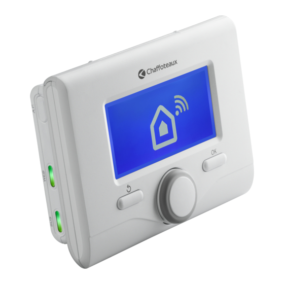
5. Tasto confi gurazione iniziale 6. Connettore 230 V AC 7. Connettore LAN 8. Connettore seriale* 9. Connettore per antenna esterna (versione GPRS) 220V BUS BUS 10. Connettore TA* 11. Connettori BUS 10 11 * Non necessario per l’installazione con Chaffoteaux Expert Control... - Page 9 4.3 Descrizione Expert Control 1. tasto indietro (visualizzazione precedente) 2. manopola 3. tasto OK (conferma l’operazione o accede al menu principale) 4. DISPLAY Simboli display: Estate ) Inverno OFF sistema spento ) Programmazione oraria ) Funzionamento manuale Indicazione presenza fi amma Temperatura ambiente desiderata Temperatura ambiente rilevata Temperatura ambiente desiderata deroga...
-
Page 10: Installazione Di Chaffolink
5.1 Tipologie di installazioni realizzabili A scopo puramente esemplicativo, si riportano nel seguente paragrafo alcuni principa- li schemi di impianto realizzabili utilizzando Chaffolink ed altri accessori già presenti nella gamma prodotti Chaffoteaux, nonché le tipologie di servizio attivabili con tali confi gurazioni. - Page 11 Azioni necessarie (fi g.2): - Rimuovere l’accessorio ON/OFF e scollegare il cavo bipolare dall’ingresso fi g.2 TA della caldaia - installare Chaffoteaux Expert Control - Installare il gateway Chaffolink GATEWAY EXPERT CONTROL Tipologia 2 Attivazione della sola TD in un siste- fi g.3 ma di riscaldamento base.
- Page 12 Attivazione di TD e TC in un sistema con 2 o più zone idrauliche controllato da dispositivi BUS. (fi g.5) Sistema in cui è presente un modulo idraulico multizona Chaffoteaux, a cui sono colle- gati accessori di gestione delle zone BUS quali Chaffoteaux Expert Control e/o Chaf- foteaux Sonda Ambiente.
- Page 13 - Installare il gateway Chaffolink e collegarlo tramite connessione BUS al sistema di riscaldamento fi g.7 fi g.8 GATEWAY MULTIFUNZIONALE EXPERT TERMOSTATO CONTROL 5.2 Installazione di Expert Control La seguente procedura deve essere eseguita per effettuare l’installazione dell’ acces- sorio fornito con Chaffolink e per sostituire un vecchio termostato eventualmente presente nell’abitazione.
- Page 14 NOTA: Per evitare problemi di interferenze, utilizzare un cavo schermato. Le seguenti versioni software di Chaffoteaux Expert Control non sono compatibili con Chaffolink: - 01.00.00 - 01.00.04 fi g. 2 In tal caso si prega di sostituire la Expert Control esistente con quella fornita nel kit Chaffolink.
- Page 15 (2.) e tirarlo verso il bas- so (3.). 2. Collegare l’altra estremità del cavo bipolare precedentemente connesso all’accessorio Chaffoteaux ad un in- gresso BUS del gateway, utilizzando uno dei connettori forniti in dotazio- 220V BUS BUS Collegamento del gateway con accessorio Chaffoteaux Expert Control...
- Page 16 5.5 Collegamento del gateway al prodotto di riscaldamento Chaffoteaux • Collegare il cavo bipolare fornito in dotazione ad uno degli ingressi BUS 220V del gateway BUS BUS • Collegare l’altra estremità del cavo al connettore BUS del prodotto di riscaldamento Chaffoteaux presente nell’abitazione.
- Page 17 5.6 Fissaggio del gateway alla parete Realizzate tutte le connessioni elettri- che tra Gateway, accessorio di termo- regolazione e prodotto di riscaldamen- to Chaffoteaux, è possibile concludere l’installazione effettuando il fi ssaggio del gateway ad una parete o base di appog- gio.
-
Page 18: Prima Accensionee Collegamento Ad Internet
6. PRIMA ACCENSIONE E COLLEGAMENTO AD INTERNET Di seguito viene descritto come collegare Chaffolink ad internet, attraverso due procedu- re differenti a seconda che venga utilizzato un gateway ADSL o GPRS. 6.1 Collegamento tramite Gateway ADSL Chaffolink è in grado di utilizzare una connessione LAN o Wi-Fi, per collegarsi ad un router ADSL. - Page 19 4. Aprire le impostazioni di rete del pro- prio dispositivo internet (smartpho- ne, PC, Tablet...) ed effettuare una ricerca delle reti Wi-Fi disponibili. Selezionare la rete Remote GW Thermo. 5. Aprire il web browser (Internet Explo- rer, Safari, Chrome, etc...) del disposi- tivo e digitare il link 192.168.1.1 nella barra degli indirizzi.
- Page 20 6.2 Collegamento tramite GPRS Utilizzando un gateway GPRS, è possibile collegare Chaffolink ad internet attraverso la seguente procedura 1. Alimentare il gateway. Premere il tasto ON/OFF. Per alcuni minuti il gateway effettua una procedura di avvio, durante la quale tutti i led lampeggiano in sequenza di colore blu.
-
Page 21: Attivazione Dei Servizi Internet
Tecnica Chaffoteaux Thermo. 7.2 Utenti fi nali Le funzioni di telecontrollo per utente fi nale sono raggiungibili scaricando l’APP uffi - ciale Chaffolink su Apple Store o Google Play o accedendo da web browser al portale Chaffolink. www.chaffolink.remotethermo.com Per ulteriori informazioni, consultare la quick guide utente compresa nella confezione o contattare (solo per l’Italia) il Servizio Clienti Chaffoteaux al numero 199.176.060*,... -
Page 22: Status Funzionamento Gateway
8. STATUS FUNZIONAMENTO GATEWAY I tre led posti nella facciata frontale del gateway permettono di avere un feedback immediato relativo allo stato di funzionamento del prodotto. Nelle seguenti tabelle sono riportate le diverse codifi che colori che si possono avere con il gateway in ver- sione ADSL e GPRS. - Page 23 CODIFICA LED IN VERSIONE GPRS Led WEB (collegamento ad internet) Spento Gateway spento Verde fi sso Gateway confi gurato correttamente Verde lampeggiante Confi gurazione Gateway in corso Blu fi sso Segnale GPRS alto Blu lampeggiante Segnale GPRS medio Rosso lampeggiante Segnale GPRS basso Rosso fi...
- Page 24 Index Overview ......................25 Safety regulations ..................26 Technical features ..................28 Product description ...................30 Chaffolink installation ................32 First start and internet connection .............40 Internet Services Activation ..............43 Gateway status ..................44...
- Page 25 1. OVERVIEW Thank you for choosing Chaffolink, the new service designed and manufactu- red by Chaffoteaux to provide a new user experience for their heating sy- stems. Through this new service it will be pos- sible to control Chaffoteaux heating...
- Page 26 2. SAFETY REGULATIONS ATTENTION This manual constitutes an integral and essential part of the product: carefully read the instructions and warnings contained in it, since they provide important notices concerning the operation and maintenance of the device itself. Please carefully store this manual in a safe place and keep it attached to the pro- duct in case of transfer to another owner or employment with a different appli- cation It is not allowed to use this product for purposes other than those specifi...
- Page 27 Do not allow children or inexperienced persons to operate the device. Damage to the device caused by improper use. CAUTION! The device is not intended for use by persons (including children) with reduced physical, sensory or mental abilities, or that lack the necessary experience and knowledge, unless they are supervised or have been adequately trained in device operation by a person responsible for their safety.
- Page 28 Buffer memory LVD 2006/95/EC EMC 2004/108/EC Conformity Electromagnetic interference Electromagnetic emissions EN 60730-1 Conformity to standards Resolution degree 0,1°C Class: V Heating contribution: +3% ERP features (only with BUS boilers) Adding an Chaffoteaux outdoor sensor: Class: VI Heating contribution: +4%...
- Page 29 Gateway 180 mm 47 mm Expert Control 134 mm 16 mm...
- Page 30 4. PRODUCT DESCRIPTION 4. 1 Package description Contents supplied within the Chaffolink package: • Gateway with power cable • Gateway wall plate • Thermoregulation accessory (Chaf- foteaux Expert Control or Chaffote- aux Zone Control) • Expert Control wall plate (only with Chaffoteaux Expert Control) •...
- Page 31 4.3 Expert Control description Buttons and Display: 1. back button (previous screen) 2. knob button (to confi rm operation or access main menu) 4. DISPLAY Display symbols: Summer ) Winter OFF, system off Time program Manual operation Flame present indication Desired room temperature Room temperature detected Desired room temperature override...
- Page 32 Chaffoteaux Net are enabled. “Remote Control” (RC) refers instead to the service oriented to the end user, through which he can use the Chaffoteaux Net smartphone app or web portale to monitor and set its Chaffoteaux products.
- Page 33 In this confi guration it is possible to keep installed the old ON/OFF thermoregula- tion accessory. Therefore it is necessary fi g.4 - Install the Chaffoteaux Net gateway - Link the gateway to the Chaffoteaux GATEWAY heating product using BUS connection BASIC CONTROL...
- Page 34 Activation of RD and RC in a 2 or more hydraulic zones system, controlled throu- gh BUS thermoregulation accessories. (fi g.5) System with an Chaffoteaux Hydraulic Module (eg: MGm II Evo) linked to BUS accesso- ries like Chaffoteaux Expert Control and Chaffoteaux Zone Control. Required actions (fi g.6):...
- Page 35 - Install the Chaffoteaux Multifunctional Kit - Install the Chaffoteaux Net gateway and link to the heating system through the BUS connection fi g.7 fi g.8 MULTIFUNCTIONAL GATEWAY EXPERT THERMOSTAT CONTROL 5.2 Installation Chaffoteaux Expert Control The following procedure has to be made in order to install the thermoregulation acces- sory supplied in the Chaffoteaux Net package and to replace an old thermostat that may be already in the dwelling.
- Page 36 NOTE: To avoid interference problems when connecting the ZONE CONTROL and boiler, use a shielded cable or twist- ed pair cable. The following software versions of Chaffoteaux Expert Control are not compatible with Chaffolink: - 01.00.00 - 01.00.04 fi g. 2...
- Page 37 2. Connect the two core cable pre- viously linked to the thermoregu- lation accessory to one of the BUS ports using one of the orange con- nectors supplied in the kit. 220V BUS BUS Connection of the gateway with Chaffoteaux Expert Control or Zone Control...
- Page 38 5.4 Gateway link to the heating product • Connect the two-core cable supplied in the package to the BUS port of the gateway, using 1 orange connector also supplied. • Connect the other end of the cable 220V BUS BUS to the BUS port of the heating pro- duct, using another orange connec- tor.
- Page 39 5.5 Gateway fi xing on a fl at surface Once all the electrical connections between the gateway, the thermore- gulation accessory and the Chaffoteaux heating product is made,it is possible to fi nish the installation by attaching the gateway to a wall or to other vertical supports.
- Page 40 6. FIRST START AND INTERNET CONNECTION In this chapter it is described how to connect the Chaffolink system to internet, through two different procedures depending on whether a ADSL or GPRS gateway version is used. 6.1 Internet connection through ADLS router...
- Page 41 192.168.1.1 6. Follow each step of the directions gi- ven in the web browser to connect Chaffolink with ADSL router. 7. Wait until the WEB led on the gate- way make a quick green fl ash. If the...
- Page 42 3. Press and hold the start-up button until the WEB led starts to fl ash a green light: the gateway is now trying to SRAmatically connect to the Chaffoteaux server. 4. If the procedure has been successful, the WEB led will remain green and the pro-...
- Page 43 7.2 End users End users can control their Chaffoteaux products through their smartphones down- loading the Chaffolink App on Apple Store or Google Play. Furthermore, it is also possible to use any internet device accessing the Chaffolink page at: www.https://www.chaffolink.remotethermo.com...
- Page 44 The three LEDs on the front cover of the gateway will allow you to receive a conti- nuous feedback regarding the status of the whole Chaffolink platform. The following tables describe the meaning of each different colour that the three LEDs could show:...
- Page 45 LED CODE GPRS VERSION WEB led Gateway OFF Steady green Gateway properly confi gured Flashing green Gateway waiting to be set up Steady Blue High GPRS signal Flashing blue Medium GPRS signal Flashing red Low GPRS signal Steady red Weak or no GPRS signal SERIAL led Gateway OFF or serial cable not used BUS led...
- Page 46 Table des matières Généralités ....................47 Consignes de sécurité ................48 Caractéristiques techniques ..............50 Description du produit ................52 Installation d'Chaffolink ................54 Premier démarrage et connexion à internet ........62 Activation des services internet ............65 État de fonctionnement passerelle ............66...
-
Page 47: Généralités
1. GÉNÉRALITÉS Merci d'avoir choisi Chaffolink, le sys- tème conçu et produit par Chaffoteaux pour fournir une nouvelle expérience d'utilisation de votre système de chauf- fage domestique. L'architecture d'Chaffolink permet de contrôler la chaudière et les autres sys- tèmes de chauffage, à partir de terminaux... -
Page 48: Consignes De Sécurité
2. CONSIGNES DE SÉCURITÉ ATTENTION Cette notice est partie intégrante et essentielle du produit. Elle doit être soi- gneusement conservée et doit toujours être jointe au produit, même en cas de transfert à un autre propriétaire ou utilisateur, ou dans le cas de l'utilisation avec une autre application. - Page 49 Endommagement de l'appareil dû à un usage impropre. Pendant le nettoyage, l'entretien et la connexion, il faut débrancher l'appareil du secteur en retirant la fi che de la prise de courant. Blessures par choc électrique Cet appareil n'est pas destiné à être utilisé par des personnes (enfants compris) dont les capacités physiques, sensorielles ou mentales sont réduites ou qui ne disposent pas des connaissances ou de l'expérience nécessaires, à...
-
Page 50: Caractéristiques Techniques
Émissions électromagnétiques EN 60730-1 conformité standard Indice de résolution 0,1°C Fonctionnalités ERP Classe : V : (uniquement avec chaudière BUS) Contribution au réchauffement : +3% En ajoutant une sonde externe Chaffoteaux : Classe : VI Contribution au réchauffement : 4%... - Page 51 Gateway 180 mm 47 mm Expert Control 134 mm 16 mm...
-
Page 52: Description Du Produit
La boîte contient : • Passerelle avec cordon d'alimentation • Plaque de fi xation de la passerelle • Accessoire thermorégulation (Chaffoteaux Expert Control ou cap- teur d'ambiance) • Plaque pour le montage mural acces- soire (uniquement avec Chaffoteaux Expert Control) •... - Page 53 4.3 Description de Expert Control 1. touche en arrière (affi chage précédent) 2. bouton 3. touche OK (confi rmer l'opération ou accéder au menu principal) 4. AFFICHEUR Légende des symboles de l'affi cheur : Été ) Hiver OFF système éteint ) Programmation horaire ) Fonctionnement manuel Indication de présence de fl...
-
Page 54: Installation D'chaffolink
«Control à distance» (CD) se réfère à l’application pour l’utilisateur fi nal, à travers laquelle il peut utiliser le Chaffoteaux net ou le portal web pour controler et commander ses pro- duits Chaffoteaux. Pour plus d’infos et de détails sur les schémas d’installation ci-dessous, nous vous prions de... - Page 55 - Retirez l’accessoire ON / OFF et débranchez le câble 2-fi ls du port TA de la chaudière fi g.2 - Installer Chaffoteaux Expert Control - Installez la passerelle Chaffoteaux Net GATEWAY EXPERT CONTROL Type 2 fi g.3 Activation de DD dans un système de chauffage de base.
- Page 56 (fi g.7) Système où sont installés des dispositifs de gestion des zones contrôlées par accessoires de thermorégulation ON / OFF. Actions requises (fi g.8): - Retirez tous les accessoires ON / OFF dans le système et remplacer avec Chaffoteaux Expert Control...
- Page 57 - Installez le Chaffoteaux Multifunctional Kit - Installez la passerelle Chaffoteaux net et un lien vers le système de chauffage à tra- vers la connexion Bus. fi g.7 fi g.8 EXPERT GATEWAY MULTIFUNCTIONAL THERMOSTAT CONTROL 5.2 Installation Chaffoteaux Expert Control La procédure suivante doit être effectuée pour installer l’accessoire fourni avec Chaffoteaux...
- Page 58 REMARQUE : Pour éviter toute interférence, utili- ser un câble blindé. Les versions suivantes des logiciels Chaffoteaux Expert Control ne sont pas compatibles avec Chaffolink : - 01.00.00 - 01.00.04 Fig. 2 Remplacer le modèle Expert Control existant avec celui fourni dans le kit Chaffolink.
- Page 59 (1). Tourner légèrement vers soi le couvercle (2) et tirer vers le bas (3). 2. Raccorder l'autre extrémité du câble bipolaire, précédemment raccordé à l'accessoire Chaffoteaux à une entrée BUS de la passerelle, en utilisant l'un des connecteurs fournis. 220V...
- Page 60 5.5 Raccordement de la passerelle au produit de chauffage Chaffoteaux • Raccorder le câble bipolaire fourni à l'une des entrées BUS de la passe- 220V relle. BUS BUS • Raccorder l'autre extrémité du câble au connecteur BUS du produit de chauffage Chaffoteaux présent dans...
- Page 61 Après avoir effectué tous les raccor- dements électriques entre la passe- relle, l'accessoire de thermorégulation et le produit de chauffage Chaffoteaux, l'installation se conclue en effectuant la fi xation de la passerelle à un mur ou à la base d'appui.
-
Page 62: Premier Démarrage Et Connexion À Internet
6. PREMIER ALLUMAGE ET CONNEXION À INTERNET La description suivante indique comment connecter Chaffolink à Internet, à travers deux procédures différentes, soit en utilisant une passerelle ADSL soit GPRS. 6.1 Connexion via passerelle ADSL Chaffolink est en mesure d'utiliser un réseau LAN ou Wi-Fi pour se connecter... - Page 63 Sélectionner le réseau Remote GW Thermo. 5. Ouvrir le navigateur Web du dispositif et aller sur le lien 192.168.1.1 6. Suivre étape par étape les indications jusqu'à l'étape fi nal. 7. Une fois arrivé à l'étape fi nal de la procédure sur le navigateur Web, le voyant WEB se met à...
- Page 64 6.2 Connexion via GPRS En utilisant une passerelle GPRS, il est possible de connecter Chaffolink à Internet via la procédure suivante. 1. Alimenter la passerelle. Appuyer sur la touche ON/OFF. La passerelle effectue pendant quelques minutes une procédure de démarrage, au cours de laquelle tous les voyants clignotent en bleu, à...
-
Page 65: Activation Des Services Internet
7.1 Centres d'assistance Chaffoteaux Les Centres d'assistance Chaffoteaux peuvent accéder à la plateforme de diagnostic à distance, en saisissant leurs identifi ants sur le portail Chaffolink. https://www.chaffolink.remotethermo.com Pour en savoir plus sur ce service, contacter le numéro vert du Centre de conseils techniques Chaffoteaux Thermo. -
Page 66: État De Fonctionnement Passerelle
8. ÉTAT DE FONCTIONNEMENT DE LA PASSERELLE Les trois voyants situés sur la façade de la passerelle permettent d'avoir un feed-back instantané de l'état de fonctionnement du produit. Les tableaux suivants présentent les différents codages de couleurs qui peuvent être présents avec la passerelle en version ADSL et GPRS. - Page 67 CODAGE LED EN VERSION GPRS Led WEB (connexion à internet) Arrêt Passerelle éteinte Vert fi xe Passerelle confi gurée correctement Vert clignotant Passerelle en attente d'être confi gurée Bleu fi xe Signal GPRS fort Bleu clignotant Signal GPRS moyen Rouge clignotant signal GPRS faible Rouge fi...
- Page 68 Chaffoteaux Thermo SpA Viale Aristide Merloni 45 60044 Fabriano (AN) Italy Telefono 0732 6011 Fax 0732 602331 www.chaffoteaux.com CHAFFOTEAUX Le Carré Pleyel - 5, rue Pleyel 93521 Saint-Denis - France Tél : 33 (0)1 55 84 94 94 fax : 33 (0)1 55 84 96 10...
Need help?
Do you have a question about the ChaffoLINK and is the answer not in the manual?
Questions and answers