Table of Contents
Advertisement
Quick Links
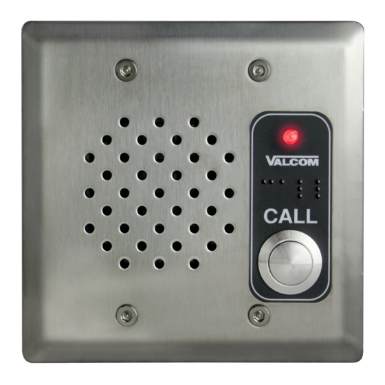
VIP-172AL IP DoorPhone/Intercom
INTRODUCTION
The VIP-172AL IP Talkback Doorphone/Intercom
allows communication to Valcom FXS units
(VIP-811, -812, -814) and SIP Based telephone
systems via an IP-based network.
SPECIFICATIONS
Access Methods
PBX, FXO Port w/VIP-811
POTS telephone set w/VIP-811
Valcom M Cast Page Group
SIP – enabled telephone system
Features
RJ-45 for network connection
1 Form C relay
Network activity LEDs
Power over Ethernet (PoE) 802.3af
compatible
Dimensions/Weight:
VIP-172AL-VRSS
4.5" H x 4.5" W x 1.75" D
(11.43cm H x 11.43cm W x 4.45cm D)
Weight: 1.68 lbs. (0.76 kg)
VIP-172AL-Brass, VIP-172AL-SS
4.5" H x 4.5" W x 1.3" D
(11.43cm H x 11.43cm W x 3.3cm D)
Weight: 0.55 lbs. (0.25 kg)
Network Interface
1.62" H x 5.63" W x 3.45" D
(4.11 cm) x (14.30 cm) x (8.73 cm)
with brackets – 8.22" W (20.87 cm)
Weight: 2.10 lbs. (0.95 kg)
VIP-172AL-BRASS
VIP-172AL-SS
Nominal Specifications
Input Impedance:
Input Level:
Output Impedance:
Output Level:
Relay Current:
Nominal Power Requirements
Via 802.3af PoE Ethernet Switch:
Environment
Network Interface:
Temperature:
Humidity:
VIP-172AL Door plate:
Suitable for indoor or outdoor installation
Packing List
Qty
1
Network Interface
1
VIP-172AL Door Plate
1
4
Tamper Hardware (VRSS unit only)
4
Door Plate Screws (Brass/SS)
1
VIP172-RLY Relay Block
1
ISSUE 1
VIP-172AL-VRSS
Network Interface
600 Ohms
-10dBm
600 Ohms
-10dBm nominal
1 AMP @ 24VDC
0 to +40° C
0 to 85% non-precipitating
Item
VSP Document
947822
Class 3
Advertisement
Table of Contents

Related Manuals for Valcom VIP-172AL


Summary of Contents for Valcom VIP-172AL
- Page 1 ISSUE 1 VIP-172AL IP DoorPhone/Intercom INTRODUCTION The VIP-172AL IP Talkback Doorphone/Intercom allows communication to Valcom FXS units (VIP-811, -812, -814) and SIP Based telephone systems via an IP-based network. SPECIFICATIONS VIP-172AL-BRASS VIP-172AL-VRSS Network Interface Access Methods VIP-172AL-SS PBX, FXO Port w/VIP-811 ...
- Page 2 Interface to the signal connector of the Network Interface customer telephone system can be via SIP then to the RJ-45 connector of the VIP-172AL registration to a voice over IP (VoIP) telephone Door Plate.
- Page 3 VALCOM LIMITED WARRANTY Valcom, Inc. warrants its products only to the original purchaser, for its own use, to be free from defects in materials and workmanship under conditions of normal use and service for a period of one year from the date of shipment. This Limited Warranty obligation shall be limited to the replacement, repair or refund of any such defective device within the warranty period, provided that: 1.
- Page 4 Step 3. Connect the RJ45 cable from the network. This device is powered via Power over Ethernet (PoE). If PoE is unavailable from the network switch then an inline power injector will be required. Step 4. Program the VIP-172AL using the VIP-102B IP Solutions Setup Tool. 350' MAXIMUM DISTANCE NETWORK...
- Page 5 Consult the door equipment manufacturer’s documentation for connections to Step 5. Program the VIP-172AL using the VIP-102B IP their device. The relay can be activated by pressing Solutions Setup Tool.
Need help?
Do you have a question about the VIP-172AL and is the answer not in the manual?
Questions and answers