Valcom V2924A User Manual
Talkback intercom system clock control card for the v-2924a
Hide thumbs
Also See for V2924A:
- User manual (16 pages) ,
- Specification sheet (4 pages) ,
- Datasheet (1 page)
Advertisement
Quick Links
Download this manual
See also:
User Manual
TALKBACK INTERCOM SYSTEM
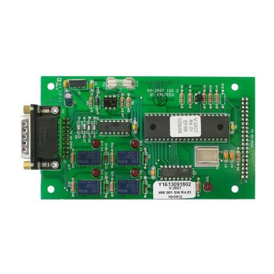
V-2927 CLOCK CONTROL CARD
INTRODUCTION
The V-2927 Clock Control Card is an optional plug-in card designed for use with the V-2924A
Talkback Intercom System with a V-2928 Option Card. It provides correction and control
functions for various impulse and synchronous clocks. The V-2927 also provides a digital output
used with the V-DCPI, Digital Clock Protocol Interface, to provide time correction data to Valcom
wired and wireless clocks. Programming of various clock types is performed via Windows
compatible Programming Tool. The V-2927 requires the use of the V-CIO Clock Interface Board
when used with mechanical time clocks.
DIMENSIONS/WEIGHT
•
5.30"L x 3.00"W x 1.10"D
(13.46cm x 7.62cm x 2.79cm)
•
0.9 lbs. (0.41 kg)
FEATURES
•
Valcom Digital Output
•
Two clock ports, independently programmable
•
24 mechanical clock types supported (see code list
on next page for types)
•
Manual clock advance (operation dependent on clock types), dial code accessible
•
Programmable adjustment for daylight savings time (DST) (operation dependent on clock
types)
•
Automatic clock correction after time update
•
Automatic clock correction after power disruption
•
Windows Programming Tool
MINIMAL SYSTEM REQUIREMENT
•
V-2924A Control Unit with V-2928 Option Card
•
V-2927 Clock Control Card
•
Rev 2.00 Programming Tool
•
Rev 2.02 Control Unit Software
•
486 or higher personal computer with Windows 95, Windows 98 or Windows NT 4.0
operating system, 8 MB RAM, 30 meg free system disk space
•
V-CIO Interface Board (for impulse clocks)
•
1 available DB9 serial communications port
FOR THE V-2924A
1
Issue 2
947012
Advertisement

Related Manuals for Valcom V2924A


Summary of Contents for Valcom V2924A
- Page 1 The V-2927 also provides a digital output used with the V-DCPI, Digital Clock Protocol Interface, to provide time correction data to Valcom wired and wireless clocks. Programming of various clock types is performed via Windows compatible Programming Tool.
-
Page 2: Operation
Call (540) 563-2000 and press 1 for Technical Support or visit our website at http://www.valcom.com. Valcom equipment is not field repairable. Valcom, Inc. maintains service facilities in Roanoke, VA. Should repairs be necessary, attach a tag to the unit clearly stating company name, address, phone number, contact person and the nature of the problem. -
Page 3: Side View
FIGURE 1 - CLOCK CARD PLACEMENT ON THE CONTROL BOARD Side View Clock Control RS232 Serial Port Card Port for SMDR (DB9 (located on Connector) Clock Card - DB15 Connector) Remove and discard plate covering P10 P1 connector port Clock Card PC Programming positions Port (located on... - Page 4 CLOCK TYPE CODES Type # Valcom Sync-wired 12-hour TED Systems A1000M & D1000 Simplex/Edwards Sync-wired 24-hour Simplex Generator Start (12 hour & Hourly Correction) Simplex/IBM Impulse, 3 Wire, 58th or 59th Minute Simplex Impulse, 2 Wire, 59th Minute Ref Utility Impulse 12VDC or 24VDC (Non-Corrective)
- Page 5 FIGURE 2 V-CIO CLOCK INTERFACE BOARD CONNECTIONS V-2927 DB15 P2 CLOCK CONTROLS V-2927 CLOCK CONTROL CONNECTIONS PIN # FUNCTION WIRE COLOR NOT USED BLACK NOT USED WHITE DIGITAL OUT+ DIGITAL OUT- GREEN NOT USED ORANGE NOT USED BLUE CLK 1 K1 C WHITE/BLACK CLK 1 K1 N/O RED/BLACK...
- Page 6 (major repairs will be subject to additional charges for parts and labor). This warranty is in lieu of and excludes all other warranties, expressed or implied and in no event shall Valcom, Inc. be liable for any anticipated profits, consequential damage, loss of time or other losses incurred by the buyer in connection with the purchase, operation or use of the product.
Need help?
Do you have a question about the V2924A and is the answer not in the manual?
Questions and answers