Table of Contents
Advertisement
Quick Links
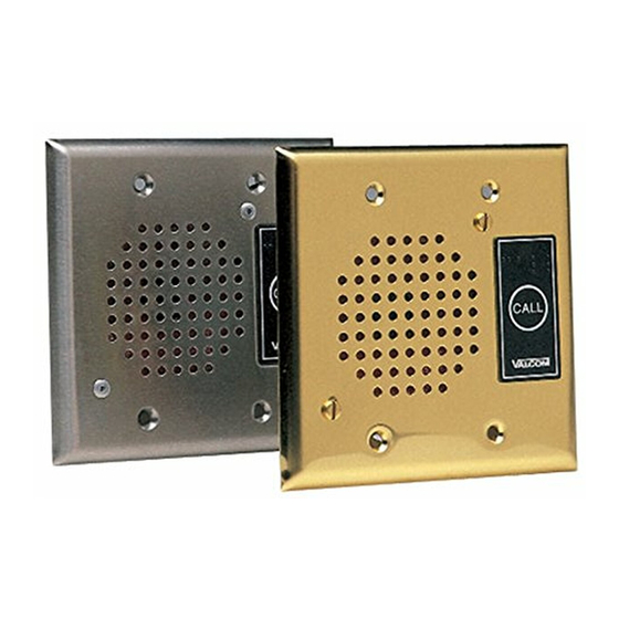
VIP-172AL IP DoorPhone/Intercom
INTRODUCTION
The VIP-172AL IP Talkback Doorphone/Intercom
allows communication to Valcom FXS units
(VIP-811, -812, -814) and SIP Based telephone
systems via an IP-based network.
SPECIFICATIONS
Access Methods
PBX, FXO Port w/VIP-811
POTS telephone set w/VIP-811
Valcom M Cast Page Group
SIP – enabled telephone system
Features
RJ-45 for network connection
1 Form C relay
Network activity LEDs
Power over Ethernet (PoE) 802.3af
compatible
Dimensions/Weight:
VIP-172AL-VRSS
4.5" H x 4.5" W x 1.75" D
(11.43cm H x 11.43cm W x 4.45cm D)
Weight: 1.68 lbs. (0.76 kg)
VIP-172AL-Brass, VIP-172AL-ST
4.5" H x 4.5" W x 1.3" D
(11.43cm H x 11.43cm W x 3.3cm D)
Weight: 0.55 lbs. (0.25 kg)
Network Interface
1.62" H x 5.63" W x 3.45" D
(4.11 cm) x (14.30 cm) x (8.73 cm)
with brackets – 8.22" W (20.87 cm)
Weight: 2.10 lbs. (0.95 kg)
VIP-172AL-BRASS
VIP-172AL-ST
Nominal Specifications
Input Impedance:
Input Level:
Output Impedance:
Output Level:
Relay Current:
Nominal Power Requirements
Via 802.3af PoE Ethernet Switch:
Environment
Network Interface:
Temperature:
Humidity:
VIP-172AL Door plate:
Suitable for indoor or outdoor installation
Packing List
Qty
1
Network Interface
1
VIP-172AL Door Plate
1
4
Tamper Hardware (VRSS unit only)
4
Door Plate Screws (Brass/SS)
1
VIP172-RLY Relay Block
1
ISSUE 2
VIP-172AL-VRSS
Network Interface
600 Ohms
-10dBm
600 Ohms
-10dBm nominal
1 AMP @ 24VDC
0 to +40° C
0 to 85% non-precipitating
Item
VSP Document
947822
Class 3
Advertisement
Table of Contents

Related Manuals for Valcom IP Solutions VIP-172AL Series


Summary of Contents for Valcom IP Solutions VIP-172AL Series
-
Page 1: Specifications
ISSUE 2 VIP-172AL IP DoorPhone/Intercom INTRODUCTION The VIP-172AL IP Talkback Doorphone/Intercom allows communication to Valcom FXS units (VIP-811, -812, -814) and SIP Based telephone systems via an IP-based network. SPECIFICATIONS VIP-172AL-BRASS VIP-172AL-VRSS Network Interface Access Methods VIP-172AL-ST PBX, FXO Port w/VIP-811 ... - Page 2 Precautionary Designations Mounting For enhanced protection against static CAUTION electrical discharge, it is recommended the faceplate shipped with the VIP-172AL be RISK OF ELECTRIC SHOCK DO NOT OPEN installed into a grounded electrical box. CAUTION: To reduce the risk of electric shock, Do not remove cover.
-
Page 3: Technical Assistance
Valcom website at www.valcom.com.Valcom Green LED: (Link) Indicates Ethernet connection equipment is not field repairable. Valcom, Inc. when illuminated. maintains service facilities in Roanoke, VA. Yellow LED: (Activity) Indicator flashes to Should repairs be necessary, attach a tag to the indicate network activity. - Page 4 NETWORK FIGURE A INTERFACE VIP-172AL Quick Start Installation Step 3 Step 1. An optional relay output is provided for activating electric door controls, strike plates, gates, etc. A Normally Open (NO) and Normally Closed (NC) connection is available. Consult the door equipment manufacturer’s Step 1 VIP-172AL documentation for connections to their device.
- Page 5 VIP-172AL High Security Relay Quick Start Installation Guide VIP-172AL NETWORK INTERFACE 350' MAXIMUM DISTANCE Step 4 Step 2 VIP-172AL DOOR PLATE Step 3 Pin 8 BROWN WHITE/BROWN GREEN WHITE/GREEN ORANGE WHITE/ORANGE BLUE Step 1 WHITE/BLUE Pin 1 = NORMALLY OPEN COM = COMMON = NORMALLY CLOSED VIP172-RLY...
Need help?
Do you have a question about the IP Solutions VIP-172AL Series and is the answer not in the manual?
Questions and answers