Advertisement
Quick Links
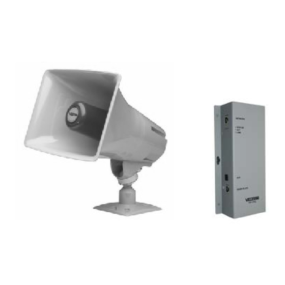
VIP-148L IP Talkback Horn
INTRODUCTION
The VIP-148L IP Talkback Horn enables two-way
handsfree voice access to a single location over
an IP-based network. This allows a page zone
extension anywhere on the network. The horn
audio level is electronically adjusted via
software. A call switch input connection is
provided for call initiation, and a line level
Auxiliary Input allows connection to a local audio
source. Power is provided to the VIP-148L via a
Power over Ethernet (PoE) switch meeting the
802.3af specification.
SPECIFICATIONS
Access Methods
PBX, FXO Port w/VIP-811
POTS telephone set w/VIP-811
FXS Port w/VIP-821
SIP telephone system
Features
RJ-45 for network connection
LED Status Indicator
Network activity LEDs
Power over Ethernet (PoE) 802.3af
compatible
Aux input for background music
Dimensions/Weight VIP-148L
Horn - 7.38" H x 10.0" W x 10.4" D
(18.75cm x 25.4cm x 26.42cm)
Network Interface – 9.13" H x 4.5" W x 1.5" D
(23.19cm x 11.43cm x 3.81cm)
Weight: 5.60 lbs. (2.54 kg)
Nominal Power Requirements
Via 802.3af (PoE) Ethernet Switch:
Environment
VIP-148L Network Interface:
Temperature:
Humidity:
VIP-148L Horn:
Suitable for indoor or outdoor installation
Packing List
Qty
1
1
1
4
4
1
1
Precautionary Designations
CAUTION: To reduce the risk of electric shock,
Refer servicing to qualified service personnel.
Class 3
1
0 to 85% non-precipitating
Item
VIP-148L Network Interface
VIP-148L Horn
VSP Document
Wood Screws
Rubber Pads
"C" Clamp
VM-186 RJ-45 Connector
CAUTION
RISK OF ELECTRIC SHOCK
DO NOT OPEN
Do not remove cover.
No user serviceable parts inside.
This symbol indicates that dangerous
voltage constituting a risk of electric
shock is present within this unit.
This symbol indicates that there are
important operating and maintenance
instructions in the literature accompanying
this unit.
Issue 4
0 to +40° C
947729
Advertisement

Related Manuals for Valcom VIP-148L


Summary of Contents for Valcom VIP-148L
- Page 1 A call switch input connection is provided for call initiation, and a line level Auxiliary Input allows connection to a local audio Environment source. Power is provided to the VIP-148L via a VIP-148L Network Interface: Power over Ethernet (PoE) switch meeting the Temperature: 0 to +40°...
- Page 2 100 meters of the network switch. Mounting (Horn) The VIP-148L Horn is designed for most FD electrical box or wall mounting and must be within 300 meters of the VIP-148L Network Interface.
- Page 3 VIP-148L to an Ethernet switch. Information specific to your application will need Signal Connections to be programmed into the VIP-148L using a computer. The PC used for programming should Connect RJ-45 patch cable using EIA/TIA 568A be connected to the same subnet as the or 568B Standard to the horn connector of the VIP-148L.
- Page 4 VALCOM LIMITED WARRANTY Valcom, Inc. warrants its products only to the original purchaser, for its own use, to be free from defects in materials and workmanship under conditions of normal use and service for a period of one year from the date of shipment. This Limited Warranty obligation shall be limited to the replacement, repair or refund of any such defective device within the warranty period, provided that: 1.