Table of Contents
Advertisement
Quick Links
Advertisement
Table of Contents

Subscribe to Our Youtube Channel
Related Manuals for Infineon VDSL6100i-E


Summary of Contents for Infineon VDSL6100i-E
- Page 1 G e t t i n g S t a r t e d , R ev . 2 , F e b . 2 00 5 V DS L6 10 0i -E V D S L 6 1 0 0 i - E E v a l ua t i o n / D e m o K i t V e r s i o n 1.
- Page 2 Infineon Technologies Components may only be used in life-support devices or systems with the express written approval of Infineon Technologies, if a failure of such components can reasonably be expected to cause the failure of that life-support device or system, or to affect the safety or effectiveness of that device or system. Life support devices or systems are intended to be implanted in the human body, or to support and/or maintain and sustain and/or protect human life.
-
Page 3: Preface
VDSL6100i-E is based on Infineon’s PEF 22827 4-band QAM VDSL Modem-on-Chip IC. VDSL6100i Data Sheet This document does not include technical details of Infineon’s VDSL6100i. The VDSL6100i data sheet is included on the VDSL6100i-E Evaluation/Demo Kit CD-ROM. About This Document This Getting Started manual is organized as follows: •... -
Page 4: Table Of Contents
VDSL6100i-E Configuration Program Main Window ........ - Page 5 VDSL6100i-E Configuration Program - Main Window ........
-
Page 6: Overview
Overview Overview This document describes how to get started with Infineon’s VDSL6100i-E Evaluation/Demo kit. Before you begin, check the contents of the kit against the Scope of Delivery. A desktop PC or laptop with an available COM port running Windows 9x/NT/2000/XP is required to support the software and hardware included in the VDSL6100i-E Evaluation/Demo Kit. -
Page 7: 6100I-E Configuration Program Installation
VDSL6100i-E Evaluation/Demo Kit 6100i-E Configuration Program Installation 6100i-E Configuration Program Installation This chapter includes the following sections: • “System Requirements” on Page 7 • “Installation” on Page 7 System Requirements • A personal computer or laptop with Microsoft Windows 9x/NT/2000/XP operating system •... -
Page 8: Hardware Setup And Initialization
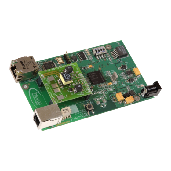
“Program Initialization” on Page 10 • “VDSL6100i-E Configuration Program Main Window” on Page 11 Hardware Description Figure 1 illustrates the layout of the major components of the VDSL6100i-E Evaluation/Demo Kit. PJ1 External Power Connector Reset PB RJ-11 VDSL Line Connector... -
Page 9: Using The Adaptive Hybrid Module
Hardware Setup Setup the VDSL6100i-E Evaluation/Demo Kit as follows: 1. Connect the CO modem (LT) to the COM Port using the COM cable supplied with the VDSL6100i-E Evaluation/Demo Kit. 2. Connect the two boards via the VDSL line interface connector WJ2 with the VDSL line cable (included with the... -
Page 10: Program Initialization
Interconnection for LT and NT VDSL6100i-E Boards A VDSL link is established, as indicated by the LNK LED (D6 in Figure 4. Start the VDSL6100i-E Configuration Program on your computer. See “Program Initialization” on Page Program Initialization Initialize the VDSL6100i-E Configuration Program as follows: 1. -
Page 11: Vdsl6100I-E Configuration Program Main Window
If you do not succeed in establishing a COM connection, refer to the VDSL6100i-E User’s Manual, Software Description, included with the Kit. When a COM port connection is detected, or if you elect to work off-line, the VDSL6100i-E Configuration Program main window appears (see... -
Page 12: Troubleshooting
“Default Link Established, but Warm-Start Link or RA Fails” on Page 13 COM Error Message Action VDSL6100i-E board connected to the PC via the COM cable, and VDSL6100i-E Configuration Program started. Problem An error message appears as shown in Figure... -
Page 13: No Link Established Indication
VDSL link will be established. To install a valid FW version, refer to Firmware Update in the VDSL6100i-E User’s Manual, Software Description. To check the FW version running on the other modem, connect to it using Configuration>Communication from the Main menu. -
Page 14: Typical Application
To establish a 10/100BaseT connection, two personal computers equipped with Ethernet NICs are necessary. The VDSL6100i-E Evaluation/Demo Board provides either a 10BaseT or 100BaseT Ethernet interface. Note: Payload data transmission over VDSL6100i-E is restricted by the VDSL link configuration. Refer to the VDSL6100i-E User’s Manual, Software Description, for more information on link configuration. -
Page 15: Terminology
VDSL6100i-E Evaluation/Demo Kit Terminology Analog Front End Automatic Gain Control ANSI American National Standards Institute Bit Error Rate Downstream ETSI European Telecommunications Standards Institute Forward Error Correction FEXT Far End Crosstalk Local Area Network Line Termination Media Access Control Media Independent Interface... - Page 16 . i n f i n e o n . c o m Published by Infineon Technologies AG...
Need help?
Do you have a question about the VDSL6100i-E and is the answer not in the manual?
Questions and answers