
Related Manuals for Cincoze CV-100/P2002 Series


Summary of Contents for Cincoze CV-100/P2002 Series
- Page 1 CV-100/P2002 Series User Manual Industrial Panel PC Performance & Power Efficient Series Version: V1.77...
-
Page 2: Table Of Contents
Contents Preface ..............................5 Revision ............................5 Copyright Notice ..........................5 Acknowledgement ......................... 5 Disclaimer ............................5 Declaration of Conformity ......................6 Product Warranty Statement ......................6 Technical Support and Assistance ....................7 Conventions Used in this Manual ....................8 Safety Precautions .......................... - Page 3 2.4 Definition of Connectors ......................72 Chapter 3 System Setup ........................78 3.1 Removing Top Cover....................... 79 3.2 Installing Half Size Mini PCIe Card ..................80 3.3 Installing Full Size Mini PCIe Card ..................82 3.4 Installing mSATA Card ......................83 3.5 Installing Antenna(s) ......................
- Page 4 4.5 Security Setup ........................125 4.6 Boot Setup ..........................126 4.7 Save & Exit ..........................127 Chapter 5 Product Application ......................128 5.1 Digital I/O (DIO) application ....................129 5.1.1 Digital I/O Programming Guide ................. 129 5.2 Digital I/O (DIO) Hardware Specification ................137 5.2.1 P2002 DIO Connector Definition ................
-
Page 5: Preface
2023/04/14 Copyright Notice © 2016 by Cincoze Co., Ltd. All rights are reserved. No parts of this manual may be copied, modified, or reproduced in any form or by any means for commercial use without the prior written permission of Cincoze Co., Ltd. All information and specification provided in this manual are for reference only and remain subject to change without prior notice. -
Page 6: Declaration Of Conformity
(such as a fuse, battery, etc.), are not warranted. Before sending your product in, you will need to fill in Cincoze RMA Request Form and obtain an RMA number from us. Our staff is available at any time to provide you with the most friendly and immediate service. -
Page 7: Technical Support And Assistance
Limitation of Liability Cincoze’ liability arising out of the manufacture, sale, or supplying of the product and its use, whether based on warranty, contract, negligence, product liability, or otherwise, shall not exceed the original selling price of the product. The remedies provided herein are the customer’s sole and exclusive remedies. -
Page 8: Conventions Used In This Manual
Conventions Used in this Manual Safety Precautions Before installing and using this device, please note the following precautions. Read these safety instructions carefully. Keep this User’s Manual for future reference. Disconnected this equipment from any AC outlet before cleaning. For plug-in equipment, the power outlet socket must be located near the equipment and must be easily accessible. - Page 9 12. Never pour any liquid into an opening. This may cause fire or electrical shock. 13. Never open the equipment. For safety reasons, the equipment should be opened only by qualified service personnel. If one of the following situations arises, get the equipment checked by service personnel: ⚫...
-
Page 10: Package Contents
Package Contents Before installation, please ensure all the items listed in the following table are included in the package. Item Description Q’ty Panel PC Screw Pack Power Terminal Block Connector Fan Terminal Block Connector DIO Terminal Block Connector Power On/Off Terminal Block Connector Screw Pack Panel Mounting Kit (The quantity varies with the size of the display module, please refer to the datasheet for the actual quantity) - Page 11 12.1" TFT XGA 4:3 Panel PC with Projected Capacitive CV-112HC/P2002E-i5 Touch and Intel 6th Gen. Core i5-6300U Expandable Fanless Computer, CFM Interface, CDS Interface 12.1" TFT XGA 4:3 Panel PC with Projected Capacitive Touch and Intel 6th Gen. Core i5-6300U Expandable CV-112HC/P2002E-i5-E4 Fanless Computer, CFM Interface, CDS Interface, 1x PCIex4 Expansion...
- Page 12 Expansion 15" TFT XGA 4:3 Panel PC with Resistive 5-wire Touch CV-115R/P2002-i5 and Intel 6th Gen. Core i5-6300U Fanless Computer, CFM Interface, CDS Interface 15" TFT XGA 4:3 Panel PC with Resistive 5-wire Touch CV-115R/P2002E-i5 and Intel 6th Gen. Core i5-6300U Expandable Fanless Computer, CFM Interface, CDS Interface 15"...
- Page 13 15" TFT XGA 4:3 Panel PC with Resistive 5-wire Touch and Intel 6th Gen. Core i3-6100U Expandable Fanless CV-115R/P2002E-i3-E4 Computer, CFM Interface, CDS Interface, 1x PCIex4 Expansion 15" TFT XGA 4:3 Panel PC with Resistive 5-wire Touch and Intel 6th Gen. Core i3-6100U Expandable Fanless CV-115R/P2002E-i3-PI Computer, CFM Interface, CDS Interface, 1x PCI Expansion...
- Page 14 Computer, CFM Interface, CDS Interface 15.6" TFT WXGA 16:9 Panel PC with Projected Capacitive CV-W115C/P2002E-i5 Touch and Intel 6th Gen. Core i5-6300U Expandable Fanless Computer, CFM Interface, CDS Interface 15.6" TFT WXGA 16:9 Panel PC with Projected Capacitive Touch and Intel 6th Gen. Core i5-6300U Expandable CV-W115C/P2002E-i5-E4 Fanless Computer, CFM Interface, CDS Interface, 1x PCIex4 Expansion...
- Page 15 15.6" TFT WXGA 16:9 Panel PC with Projected Capacitive Touch and Intel 6th Gen. Core i3-6100U Expandable CV-W115C/P2002E-i3-PI Fanless Computer, CFM Interface, CDS Interface, 1x PCI Expansion 17" TFT SXGA 5:4 Panel PC with Resistive 5-wire Touch CV-117R/P2002-i5 and Intel 6th Gen. Core i5-6300U Fanless Computer, CFM Interface, CDS Interface 17"...
- Page 16 17" TFT SXGA 5:4 Panel PC without Touch, w/ Intel 6th CV-117G/P2002E-i5-E4 Gen. Core i5-6300U Expandable Fanless Computer, CFM Interface, CDS Interface, 1x PCIex4 Expansion 17" TFT SXGA 5:4 Panel PC without Touch, w/ Intel 6th CV-117G/P2002E-i5-PI Gen. Core i5-6300U Expandable Fanless Computer, CFM Interface, CDS Interface, 1x PCI Expansion 17"...
- Page 17 17" TFT SXGA 5:4 Panel PC without Touch, w/ Intel 6th CV-117G/P2002E-i3 Gen. Core i3-6100U Expandable Fanless Computer, CFM Interface, CDS Interface 17" TFT SXGA 5:4 Panel PC without Touch, w/ Intel 6th CV-117G/P2002E-i3-E4 Gen. Core i3-6100U Expandable Fanless Computer, CFM Interface, CDS Interface, 1x PCIex4 Expansion 17"...
- Page 18 19" TFT SXGA 5:4 Panel PC without Touch, w/ Intel 6th CV-119G/P2002-i5 Gen. Core i5-6300U Fanless Computer, CFM Interface, CDS Interface 19" TFT SXGA 5:4 Panel PC without Touch, w/ Intel 6th CV-119G/P2002E-i5 Gen. Core i5-6300U Expandable Fanless Computer, CFM Interface, CDS Interface 19"...
- Page 19 Fanless Computer, CFM Interface, CDS Interface 1x PCI Expansion 19" TFT SXGA 5:4 Panel PC without Touch, w/ Intel 6th CV-119G/P2002-i3 Gen. Core i3-6100U Fanless Computer, CFM Interface, CDS Interface 19" TFT SXGA 5:4 Panel PC without Touch, w/ Intel 6th CV-119G/P2002E-i3 Gen.
- Page 20 Interface 1x PCIex4 Expansion 21.5" TFT Full HD 16:9 Panel PC with Projected Capacitive Touch and Intel 6th Gen. Core i5-6300U CV-W121C/P2002E-i5-PI Expandable Fanless Computer, CFM Interface, CDS Interface 1x PCI Expansion 21.5" TFT Full HD 16:9 Panel PC without Touch, w/ Intel CV-W121G/P2002-i5 6th Gen.
- Page 21 Interface 21.5" TFT Full HD 16:9 Panel PC with Projected Capacitive Touch and Intel 6th Gen. Core i3-6100U CV-W121C/P2002E-i3-E4 Expandable Fanless Computer, CFM Interface, CDS Interface 1x PCIex4 Expansion 21.5" TFT Full HD 16:9 Panel PC with Projected Capacitive Touch and Intel 6th Gen. Core i3-6100U CV-W121C/P2002E-i3-PI Expandable Fanless Computer, CFM Interface, CDS Interface 1x PCI Expansion...
- Page 22 24" TFT Full HD 16:9 Panel PC with Projected Capacitive CV-W124C/P2002E-i5 Touch and Intel 6th Gen. Core i5-6300U Expandable Fanless Computer, CFM Interface, CDS Interface 24" TFT Full HD 16:9 Panel PC with Projected Capacitive Touch and Intel 6th Gen. Core i5-6300U Expandable CV-W124C/P2002E-i5-E4 Fanless Computer, CFM Interface, CDS Interface, 1x PCIex4 Expansion...
- Page 23 24" TFT Full HD 16:9 Panel PC without Touch, w/ Intel CV-W124G/P2002-i5 6th Gen. Core i5-6300U Fanless Computer, CFM Interface, CDS Interface 24" TFT Full HD 16:9 Panel PC without Touch, w/ Intel CV-W124G/P2002E-i5 6th Gen. Core i5-6300U Expandable Fanless Computer, CFM Interface, CDS Interface 24"...
-
Page 24: Chapter 1 Product Introductions
Chapter 1 Product Introductions P2002 Series | User Manual CV-100/... -
Page 25: Overview
PoE and ignition sensing functions with additional CFM boards. In addition, Cincoze offers a full series of Mini-PCIe Expansion I/O Card (MEC) for adding extra I/O through the universal bracket. The CV-100/P2002 Series comes with the slim version, and the expandable version... -
Page 26: Product Pictures
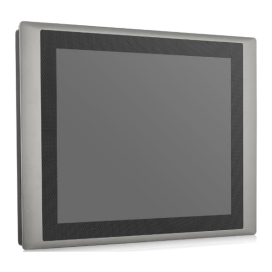
1.3 Product Pictures 1.4 Key Features ⚫ 12.1” ~ 24” TFT LCD with Resistive 5-wire Touch, Projected Capacitive Touch or Glass Only (Available on Selected Models) ⚫ Onboard Intel® 6th Generation Core™ Processor U Series (15W) ⚫ 2x DDR4 SO-DIMM Socket, Support Up to 32 GB ⚫... -
Page 27: Hardware Specification
1.5 Hardware Specification 1.5.1 CV-112H/P2002 Series The table on this page refers to the specifications of CV-112H alone Model Name CV-112HR CV-112HC Display • 12.1" (4:3) LCD Size • Max. Resolution 1024 x 768 • 500 Brightness( cd/m2) • Contract Ratio 700 : 1 •... - Page 28 Model Name P2002 P2002E System Processor • Onboard 6th Intel® Core™ U processors (Skylake) • Intel® Core™ i5-6300U processor (3M Cache, up to 3.00 GHz) • Intel® Core™ i3-6100U processor (3M Cache, 2.30 GHz) • TDP: 15 W Memory 2x DDR4 2133 MHz SO-DIMM Sockets •...
- Page 29 • Optional Riser Card: 1x PCI, 1x PCIex4 • Support maximum dimension of add-on card (H x L):100mm x 200mm • Mini PCI Express 2x Full-size Mini-PCIe Socket • SIM Socket 1x SIM Socket CFM (Control Function Optional CFM IGN Module for Power Ignition Function •...
- Page 30 • Microsoft® Windows® Windows®10, Windows® 8.1, Windows® 7 • Linux Linux® Kernel 4.4 Environment • Operating Temperature: -25°C to 70°C Operating Temperature (With extended temperature peripherals; Ambient with air flow According to IEC60068-2-1, IEC60068-2-2, IEC60068-2-14) • Storage Temperature Storage Temperature: -40°C to 85°C •...
- Page 31 Dimensions CV-112H/P2002 CV-112H/P2002E P2002 Series | User Manual CV-100/...
-
Page 32: Cv-115/P2002 Series
1.5.2 CV-115/P2002 Series The table on this page refers to the specifications of CV-115 alone Model Name CV-115R CV-115C Display • 15" (4:3) LCD Size • Max. Resolution 1024 x 768 • 350 Brightness( cd/m2) • Contract Ratio 800 : 1 •... - Page 33 Model Name P2002 P2002E System Processor • Onboard 6th Intel® Core™ U processors (Skylake) • Intel® Core™ i5-6300U processor (3M Cache, up to 3.00 GHz) • Intel® Core™ i3-6100U processor (3M Cache, 2.30 GHz) • TDP: 15 W Memory 2x DDR4 2133 MHz SO-DIMM Sockets •...
- Page 34 PCI Express 1x PCI or 1x PCIex4 Expansion slot • • Optional Riser Card: 1x PCI, 1x PCIex4 • Support maximum dimension of add-on card (H x L):100mm x 200mm • Mini PCI Express 2x Full-size Mini-PCIe Socket • SIM Socket 1x SIM Socket CFM (Control Function Optional CFM IGN Module for Power Ignition Function...
- Page 35 Operating System • Microsoft® Windows® Windows®10, Windows® 8.1, Windows® 7 • Linux Linux® Kernel 4.4 Environment • Operating Temperature: -25°C to 70°C Operating Temperature (With extended temperature peripherals; Ambient with air flow According to IEC60068-2-1, IEC60068-2-2, IEC60068-2-14) • Storage Temperature Storage Temperature: -40°C to 85°C •...
- Page 36 Dimensions CV-115/P2002 CV-115/P2002E P2002 Series | User Manual CV-100/...
-
Page 37: Cv-W115/P2002 Series
1.5.3 CV-W115/P2002 Series The table on this page refers to the specifications of CV-W115 alone Model Name CV-W115R CV-W115C Display • 15.6" (16:9) LCD Size • Max. Resolution 1366 x 768(WXGA) • 400 Brightness( cd/m2) • Contract Ratio 500 : 1 •... - Page 38 Model Name P2002 P2002E System Processor • Onboard 6th Intel® Core™ U processors (Skylake) • Intel® Core™ i5-6300U processor (3M Cache, up to 3.00 GHz) • Intel® Core™ i3-6100U processor (3M Cache, 2.30 GHz) • TDP: 15 W Memory 2x DDR4 2133 MHz SO-DIMM Sockets •...
- Page 39 • Optional Riser Card: 1x PCI, 1x PCIex4 • Support maximum dimension of add-on card (H x L):100mm x 200mm • Mini PCI Express 2x Full-size Mini-PCIe Socket • SIM Socket 1x SIM Socket CFM (Control Function Optional CFM IGN Module for Power Ignition Function •...
- Page 40 • Microsoft® Windows® Windows®10, Windows® 8.1, Windows® 7 • Linux Linux® Kernel 4.4 Environment • Operating Temperature: -25°C to 70°C Operating Temperature (With extended temperature peripherals; Ambient with air flow According to IEC60068-2-1, IEC60068-2-2, IEC60068-2-14) • Storage Temperature Storage Temperature: -40°C to 85°C •...
- Page 41 Dimensions CV-W115/P2002 CV-W115/P2002E P2002 Series | User Manual CV-100/...
-
Page 42: Cv-117/P2002 Series
1.5.4 CV-117/P2002 Series The table on this page refers to the specifications of CV-117 alone Model Name CV-117R CV-117C CV-117G Display • 17" (5:4) LCD Size • Max. Resolution 1280 x 1024 • 350 Brightness( cd/m2) • Contract Ratio 800 : 1 •... - Page 43 Model Name P2002 P2002E System Processor • Onboard 6th Intel® Core™ U processors (Skylake) • Intel® Core™ i5-6300U processor (3M Cache, up to 3.00 GHz) • Intel® Core™ i3-6100U processor (3M Cache, 2.30 GHz) • TDP: 15 W Memory 2x DDR4 2133 MHz SO-DIMM Sockets •...
- Page 44 • Optional Riser Card: 1x PCI, 1x PCIex4 • Support maximum dimension of add-on card (H x L):100mm x 200mm • Mini PCI Express 2x Full-size Mini-PCIe Socket • SIM Socket 1x SIM Socket CFM (Control Function Optional CFM IGN Module for Power Ignition Function •...
- Page 45 • Microsoft® Windows® Windows®10, Windows® 8.1, Windows® 7 • Linux Linux® Kernel 4.4 Environment • Operating Temperature: -25°C to 70°C Operating Temperature (With extended temperature peripherals; Ambient with air flow According to IEC60068-2-1, IEC60068-2-2, IEC60068-2-14) • Storage Temperature Storage Temperature: -40°C to 85°C •...
- Page 46 Dimensions CV-117/P2002 CV-117/P2002E P2002 Series | User Manual CV-100/...
-
Page 47: Cv-119/P2002 Series
1.5.5 CV-119/P2002 Series The table on this page refers to the specifications of CV-119 alone Model Name CV-119R CV-119C CV-119G Display • 19" (5:4) LCD Size • Max. Resolution 1280 x 1024 • 350 Brightness( cd/m2) • Contract Ratio 1000 : 1 •... - Page 48 Model Name P2002 P2002E System Processor • Onboard 6th Intel® Core™ U processors (Skylake) • Intel® Core™ i5-6300U processor (3M Cache, up to 3.00 GHz) • Intel® Core™ i3-6100U processor (3M Cache, 2.30 GHz) • TDP: 15 W Memory 2x DDR4 2133 MHz SO-DIMM Sockets •...
- Page 49 • Optional Riser Card: 1x PCI, 1x PCIex4 • Support maximum dimension of add-on card (H x L):100mm x 200mm • Mini PCI Express 2x Full-size Mini-PCIe Socket • SIM Socket 1x SIM Socket CFM (Control Function Optional CFM IGN Module for Power Ignition Function •...
- Page 50 • Microsoft® Windows® Windows®10, Windows® 8.1, Windows® 7 • Linux Linux® Kernel 4.4 Environment • Operating Temperature: -25°C to 70°C Operating Temperature (With extended temperature peripherals; Ambient with air flow According to IEC60068-2-1, IEC60068-2-2, IEC60068-2-14) • Storage Temperature Storage Temperature: -40°C to 85°C •...
- Page 51 Dimensions CV-119/P2002 CV-119/P2002E P2002 Series | User Manual CV-100/...
-
Page 52: Cv-W121/P2002 Series
1.5.6 CV-W121/P2002 Series The table on this page refers to the specifications of CV-W121 alone Model Name CV-W121R CV-W121C CV-W121G Display • 21.5" (16:9) LCD Size • Max. Resolution 1920 x 1080 • 350 Brightness( cd/m2) • Contract Ratio 5000 : 1 •... - Page 53 Model Name P2002 P2002E System Processor • Onboard 6th Intel® Core™ U processors (Skylake) • Intel® Core™ i5-6300U processor (3M Cache, up to 3.00 GHz) • Intel® Core™ i3-6100U processor (3M Cache, 2.30 GHz) • TDP: 15 W Memory 2x DDR4 2133 MHz SO-DIMM Sockets •...
- Page 54 • Optional Riser Card: 1x PCI, 1x PCIex4 • Support maximum dimension of add-on card (H x L):100mm x 200mm • Mini PCI Express 2x Full-size Mini-PCIe Socket • SIM Socket 1x SIM Socket CFM (Control Function Optional CFM IGN Module for Power Ignition Function •...
- Page 55 • Microsoft® Windows® Windows®10, Windows® 8.1, Windows® 7 • Linux Linux® Kernel 4.4 Environment • Operating Temperature: -25°C to 70°C Operating Temperature (With extended temperature peripherals; Ambient with air flow According to IEC60068-2-1, IEC60068-2-2, IEC60068-2-14) • Storage Temperature Storage Temperature: -40°C to 85°C •...
- Page 56 Dimensions CV-W121/P2002 CV-W121/P2002E P2002 Series | User Manual CV-100/...
-
Page 57: Cv-W124/P2002 Series
1.5.7 CV-W124/P2002 Series The table on this page refers to the specifications of CV-W124 alone Model Name CV-W124R CV-W124C CV-W124G Display • 24" (16:9) LCD Size • Max. Resolution 1920 x 1080 • 300 Brightness( cd/m2) • Contract Ratio 5000 : 1 •... - Page 58 Model Name P2002 P2002E System Processor • Onboard 6th Intel® Core™ U processors (Skylake) • Intel® Core™ i5-6300U processor (3M Cache, up to 3.00 GHz) • Intel® Core™ i3-6100U processor (3M Cache, 2.30 GHz) • TDP: 15 W Memory 2x DDR4 2133 MHz SO-DIMM Sockets •...
- Page 59 • Optional Riser Card: 1x PCI, 1x PCIex4 • Support maximum dimension of add-on card (H x L):100mm x 200mm • Mini PCI Express 2x Full-size Mini-PCIe Socket • SIM Socket 1x SIM Socket CFM (Control Function Optional CFM IGN Module for Power Ignition Function •...
- Page 60 • Microsoft® Windows® Windows®10, Windows® 8.1, Windows® 7 • Linux Linux® Kernel 4.4 Environment • Operating Temperature: -25°C to 70°C Operating Temperature (With extended temperature peripherals; Ambient with air flow According to IEC60068-2-1, IEC60068-2-2, IEC60068-2-14) • Storage Temperature Storage Temperature: -40°C to 85°C •...
- Page 61 Dimensions CV-W124/P2002 CV-W124/P2002E P2002 Series | User Manual CV-100/...
-
Page 62: System I/O
1.6 System I/O 1.6.1 Front DC IN USB 3.0 Used to plug a DC power input with terminal block Used to connect to USB 3.0/2.0/1.1 compatible DVI-D devices Used to connect to a monitor with digital signal USB 2.0 interface Used to connect to USB 2.0/1.1 compatible devices Digital I/O Terminal Block Used to connect to a monitor with analog signal... -
Page 63: Rear
1.6.2 Rear CFast and SIM Card Power On/Off Switch CFast card and SIM card slot Power-on or power-off the system HDD/SSD 2.5” SATA HDD/SSD Bay, Support RAID 0/1 1.6.3 Side (Left) Antenna Hole Power LED Used to connect an antenna for optional Mini-PCIe Indicates the power status of the system WiFi module HDD LED... -
Page 64: Side (Right)
1.6.4 Side (Right) Antenna Hole Used to connect an antenna for optional Mini-PCIe Used to connect to RS-232/422/485 serial devices WiFi module 1.6.5 Top VESA Mounting Hole These are mounting holes for VESA mount (75x75mm and 100x100mm) P2002 Series | User Manual CV-100/... -
Page 65: Chapter 2 Switches & Connectors
Chapter 2 Switches & Connectors P2002 Series | User Manual CV-100/... -
Page 66: Location Of The Switches/Connectors
2.1 Location of the Switches/Connectors 2.1.1 Top View P2002 Series | User Manual CV-100/... -
Page 67: Bottom View
2.1.2 Bottom View P2002 Series | User Manual CV-100/... -
Page 68: Definition Of Switches/Connectors
2.2 Definition of Switches/Connectors List of Jumpers/Switches/Connectors Location Definition AT_ATX1 AT / ATX Power Mode Switch BL_PWR1 Backlight Power on / off switching BL_UP1 Backlight Increase BL_DN1 Backlight Decrease CFAST1 CFast Connector COM3~6 with Power Select COM1_1, COM2_1, COM3_1 RS232 / RS422 / RS485 Connector COM4_1, COM5_1, COM6_1 Function setting DC_IN1... -
Page 69: Definition Of Switches
2.3 Definition of Switches Super CAP Function Setting: Pin Define SW2 Switch Switch mode Function Super CAP Enable (Default) Disable Clear CMOS Function Setting : Pin Define SW2 Switch Switch mode Function CMOS Clear CMOS Normal (Default) COM1/2 Voltage Function Setting : Pin Define SW2 Switch Switch mode Function ON/ON (Default) - Page 70 COM3/4/5/6 Voltage Function Setting : Pin Define SW1 Switch Switch mode Function ON/ON (Default) COM3 ON/OFF OFF/OFF ON/ON (Default) COM4 ON/OFF OFF/OFF ON/ON (Default) COM5 ON/OFF OFF/OFF ON/ON (Default) COM6 ON/OFF OFF/OFF AT_ATX1: AT / ATX Power Mode Switch Definition 1-2 (Left) AT Power Mode 2-3 (Right)
- Page 71 BL_PWR1: Backlight Power on / off Switch Definition Push Backlight Power on / off switching BL_UP1: Backlight Increase Switch Definition Push Backlight Increase BL_DN1: Backlight Decrease Switch Definition Push Backlight Decrease RESET1: Reset Switch Switch Definition Push Reset System P2002 Series | User Manual CV-100/...
-
Page 72: Definition Of Connectors
2.4 Definition of Connectors COM1_1/COM2_1/(COM3_1/COM4_1/COM5_1/COM6_1 on the BTB Board): RS232 / RS422 / RS485 Connector Connector Type: 9-pin D-Sub RS422 / 485 RS485 RS232 Definition Full Duplex Half Duplex Definition Definition DATA - DATA + DC_IN1: DC Power Input Connector (+9~48V) Connector Type: Terminal Block 1X3 3-pin, 5.0mm pitch Definition +9~48VIN... - Page 73 LED1: Power / HDD Access LED Status LED Status LED Color Yellow POWER Green POWER3: Power Connector Connector Type: 1X4-pin Wafer, 2.0mm pitch Definition +12V POWER4: Power Connector Connector Type: 1X4-pin Wafer, 2.0mm pitch Definition +12V FAN1: External PWM Fan Connector Connector Type: Terminal Block 1X3 3-pin, 3.5mm pitch Definition +12V...
- Page 74 CN1: Mini PCI-Express Socket (SIM Card to Link) Pin Definition Pin Definition Pin Definition WAKE# RESERVED +3.3V +3.3V USB_D+ RESERVED PERST# PERN0 +3.3V +1.5V +3.3V CLKREQ# PERN0 RESERVED SIM_DATA +1.5V REFCLK+ SIM_CLK SMB_CLK +1.5V REFCLK+ PETN0 SIM_RESET SMB_DATA PETP0 SIM_VPP +3.3V USB_D- P2002 Series | User Manual...
- Page 75 CN2: Mini PCI-Express Socket / mSATA Socket Pin Definition Pin Definition Pin Definition WAKE# +3.3V +3.3V USB_D+ +3.3V PERST# PERN0/SATAPR0 +3.3V +1.5V +3.3VAUX CLKREQ# PERN0/SATARN0 +1.5V REFCLK+ SMB_CLK +1.5V REFCLK+ PETN0 SMB_DATA PETP0 +3.3V USB_D- P2002 Series | User Manual CV-100/...
- Page 76 CN3: mSATA Socket Pin Definition Pin Definition Pin Definition WAKE# +3.3V +3.3V USB_D+ +3.3V PERST# SATARXP +3.3V +1.5V +3.3V SATARXN +1.5V SMB_CLK +1.5V SATATXN SMB_DATA SATATXP +3.3V USB_D- P2002 Series | User Manual CV-100/...
- Page 77 Power Ignition Setting (CFM-IGN100 Only) Connector Location Definition Ignition Function Setting 24V_12V_1 24V/ 12V Power Switching for Ignition Board IGN Board Pin define (CFM-IGN100 Only) SW2: Set shutdown delay timer when ACC is turned off Pin 1 Pin 2 Pin 3 Pin 4 Definition 0 second...
-
Page 78: Chapter 3 System Setup
Chapter 3 System Setup P2002 Series | User Manual CV-100/... -
Page 79: Removing Top Cover
This chapter takes P2002E as an example to demonstrate the installation of hardware components. 3.1 Removing Top Cover Loosen the 6 screws at front and rear panel, then place them aside. Raise the left edge of top cover (1), and raise the other side (2) subsequently to remove it from the chassis. -
Page 80: Installing Half Size Mini Pcie Card
Place the top cover aside gently. 3.2 Installing Half Size Mini PCIe Card Locate the Mini PCIe slot. Use provided two screws on bracket to fasten the module and bracket together. P2002 Series | User Manual CV-100/... - Page 81 Tilt the Mini PCIe card at a 45-degree angle and insert it into the socket until the golden finger connector of the card seated firmly. ° Press down the module and use the two screws to fix the module. P2002 Series | User Manual CV-100/...
-
Page 82: Installing Full Size Mini Pcie Card
3.3 Installing Full Size Mini PCIe Card 1. Locate the Mini PCIe slot. 2. Tilt the Mini PCIe card at a 45-degree angle and insert it to the socket until the golden finger connector of the card seated firmly. 45° 3. -
Page 83: Installing Msata Card
3.4 Installing mSATA Card Locate the mSATA slot on the system board. Tilt the mSATA card at a 45-degree angle and insert it to the socket until the golden finger connector of the card seated firmly. 45° Fasten the card with two screws. P2002 Series | User Manual CV-100/... -
Page 84: Installing Antenna(S)
3.5 Installing Antenna(s) Remove the antenna rubber covers on left and right panel. Penetrate the antenna jack through the hole. Put on the washer and fasten the nut with antenna jack. P2002 Series | User Manual CV-100/... - Page 85 Assemble the antenna and antenna jack together. Attach the RF connector at another end of the cable onto the card. P2002 Series | User Manual CV-100/...
-
Page 86: Installing So-Dimm Memory
3.6 Installing SO-DIMM Memory 1. Locate SO-DIMM socket. 2. Tilt the SODIMM module at a 45-degree angle and insert it to SODIMM socket until the gold-pated connector of module contacted firmly with the socket. 3. Press the module down until its fixed firmly by the two locking latches on each side. P2002 Series | User Manual CV-100/... -
Page 87: Installing Pci(E) Card
3.7 Installing PCI(e) Card 1. Locate the retention module of PCI(e) expansion card. 2. Loosen one screw halfway as indicated to have the clamp arm slidable. clamp arm 3. Loosen one screw to remove the PCI bracket. P2002 Series | User Manual CV-100/... - Page 88 4. Align the notch of golden fingers of PCI(e) card with the expansion slot. Insert the card horizontally, and press the card straight down into the slot until it’s seated firmly. 5. Fasten one screw to secure the PCI(e) expansion card. 6.
-
Page 89: Installing Thermal Pad Of Thermal Block
7. Finally, fasten the screw that were previously loosen halfway to fix the retention module. 3.8 Installing Thermal Pad of Thermal Block Place thermal pad on the top of CPU thermal block in order to provide a seamless contact with the body of chassis to create an efficient heat dissipation. -
Page 90: Installing Cfm-Ign Module (Optional)
3.9 Installing CFM-IGN Module (Optional) Locate the power Ignition connector on system motherboard as indicated. Insert the female connector of power ignition board to the male connector on system motherboard. Fasten two screws to secure the power ignition board. P2002 Series | User Manual CV-100/... -
Page 91: Installing Cfm-Poe Module (Optional)
3.10 Installing CFM-PoE Module (Optional) This chapter takes CFM-PoE101 for example. 1. Locate the PoE connector on system motherboard as indicated. 2. Insert the female connector of PoE daughter board to the male connector on system motherboard. 3. Fasten two screws to secure the PoE board. P2002 Series | User Manual CV-100/... -
Page 92: Installing Top Cover
3.11 Installing Top Cover 1. Put on the left edge of top cover onto system, and the other side subsequently. 2. Fasten the six screws at front and rear panel to secure the top cover. P2002 Series | User Manual CV-100/... -
Page 93: Installing Sata Hard Drive At Front Panel
3.12 Installing SATA Hard Drive at Front Panel 1. Turn over the system to bottom side, and remove one screw. 2. Loosen the two screws to remove the HDD bay cover bracket. 3. Pull the rotating arm of HDD bracket outward as indicated. P2002 Series | User Manual CV-100/... - Page 94 4. Hold the rotating arm to pull out the HDD bracket. 5. Place the HDD bracket on screw-hole side of HDD. Use four screws provided to assemble HDD on the bracket. 6. Align the HDD bracket with the entrance of HDD bay. And insert the HDD bracket and push it until the edge connector of HDD fully inserted into SATA slot.
-
Page 95: Installing Sata Hard Drive On Bottom Side
7. Put back HDD bay cover at front panel, and fasten it with two screws. 8. Fasten one screw to secure the HDD bracket on the system chassis. 3.13 Installing SATA Hard Drive on Bottom Side Turn over the system to bottom side. Locate the cover of HDD compartment. P2002 Series | User Manual CV-100/... - Page 96 Loosen the two screws, then pull the cover to remove it. Loosen three screws and take the HDD bracket out of HDD compartment. Place the HDD bracket on screw-hole side of HDD. Use four screws provided to assemble HDD on the bracket. P2002 Series | User Manual CV-100/...
- Page 97 Seat the HDD bracket into HDD compartment, and line up the connector of HDD with SATA slot, then push it until HDD is fully connected into slot. Secure the HDD bracket with three screws. Put back the cover and fasten the two screws. P2002 Series | User Manual CV-100/...
-
Page 98: Installing Sim Card
3.14 Installing SIM Card 1. Locate the SIM card slot at front panel. 2. Loosen two screws to remove the cover plate. 3. Insert the SIM card. P2002 Series | User Manual CV-100/... -
Page 99: Installing Cfast Card
3.15 Installing CFast Card 1. Locate the CFast card slot at front panel. 2. Loosen the two screws to remove the cover plate. 3. Insert a CFast card until it clicks. 4. Fasten two screws to secure the cover plate. P2002 Series | User Manual CV-100/... -
Page 100: Connecting With Cv Display Module
3.16 Connecting with CV Display Module 1. Prepare the mounting kit that accompanied with P2002 as shown. (including two mounting brackets and one screw pack) 2. Remove six screws at left and right panel of PC2000. 3. Assemble two mounting brackets to left and right panel of PC2000 by fastening three screws at each side. - Page 101 4. Turn over the system to bottom side. Locate the connector cover of display module. 5. Loosen two screws to remove the cover. The following photos indicates the male connector (on display module) and female connector (on P2002). P2002 Series | User Manual CV-100/...
- Page 102 6. Place the P2002 on the display module through its display connector hole as indicated. 7. Align the mounting holes of P2002 with the screw holes of display module underneath. Then slide the PC2000 carefully as indicated to have P2002 and display module connected together. 8.
-
Page 103: Installing Vesa Mount
3.17 Installing VESA Mount The following picture indicates VESA mounting hole pattern on P2002, which is compliant with VESA mounting standard. 1. The following picture uses a panel PC (P2002+CV display module) as a demonstration. To attach the panel PC to a VESA stand, please fasten eight screws as indicated to fix it on the stand. (Please refer to section 3.16 in this manual for how to attach PC2002 to CV display module.) P2002 + CV display module... -
Page 104: Installing Panel Mount
3.18 Installing Panel Mount 1. Accessories provided by Cincoze are as follows. (Please note that the quantity of mounting kits varies with the size of the display module, please refer to the datasheet for the actual quantity) P2002 Series | User Manual... - Page 105 2. All mounting kits displayed are to be inserted into holes. 3. Installation preparation and steps. P2002 Series | User Manual CV-100/...
- Page 106 P2002 Series | User Manual CV-100/...
- Page 107 4. Apply all mount kits to the rest of holes. And you have completed the panel mount installation, as shown below. P2002 Series | User Manual CV-100/...
-
Page 108: Chapter 4 Bios Setup
Chapter 4 BIOS Setup P2002 Series | User Manual CV-100/... -
Page 109: Bios Introduction
4.1 BIOS Introduction The BIOS (Basic Input/ Output System) is a program located on a Flash Memory on the motherboard. When you start the computer, the BIOS program will gain control. The BIOS first operates an auto-diagnostic test called POST (power on self-test) for all the necessary hardware, it detects the entire hardware device and configures the parameters of the hardware synchronization. -
Page 110: Main Setup
4.2 Main Setup Press <Del> to enter BIOS CMOS Setup Utility, the Main Menu (as shown below) will appears on the screen. Use arrow keys to move among the items and press <Enter> to accept or enter a sub-menu. 4.2.1 System Date Set the date. -
Page 111: Advanced Setup
4.3 Advanced Setup 4.3.1 ACPI Settings Enable or disable ACPI Auto Configuration. ■ Enable ACPI Auto Configuration [Enabled] Enables or disables BIOS ACPI Auto Configuration. P2002 Series | User Manual CV-100/... -
Page 112: Amt Configuration
4.3.2 AMT Configuration This screen allows users to configure related settings of Intel® Active Management Technology. ■ Intel AMT [Enabled] Allows you to enable or disable Intel® Active Management Technology BIOS execution. ■ Un-Configure ME [Disabled] Sets this item to [Disabled] to unconfigure AMT/ME without using a password or set it to [Enabled] to use a password. -
Page 113: F81866 Super Io Configuration
■ Firmware Update Configuration ❑ ME FW Image Re-Flash [Disabled] Allows you to enable or disable ME firmware image re-flash function. 4.3.4 F81866 Super IO Configuration You can use this screen to select options for the Super IO Configuration, and change the value of the selected option. -
Page 114: Hardware Monitor
❑ Change Settings [Auto] Used to change the address & IRQ settings of the specified serial port. ❑ Onboard Serial Port 1 Mode [RS232] Change the Serial interface. Select <RS232>, <RS422> or <RS485> interface. ■ Watch Dog [Disabled] You can setup the system watch-dog timer, a hardware timer that generates a reset when the software that it monitors does not respond as expected each time the watch dog polls it. -
Page 115: S5 Rtc Wake Settings
4.3.6 S5 RTC Wake Settings ■ Wake System from S5 [Disabled] This item allows users to change the way to wake system from S5 state. [Fixed Time]: Set the specified time (HH:MM:SS) to wake system. [Dynamic Time]: Set the increase time from current time to wake system. 4.3.7 Serial Port Console Redirection ■... -
Page 116: Cpu Configuration
4.3.8 CPU Configuration ■ Hyper-Threading [Enabled] Allows you to enable or disable Intel® Hyper-Threading function of processor. ■ Active Process Cores [All] Allows you to choose the number of active processor cores. Configuration options: [All] [1]. ■ Intel® Virtualization Technology [Enabled] Enables or disables Intel®... -
Page 117: Sata Configuration
4.3.9 SATA Configuration ■ Serial Controller(s) [Enabled] Allows you to enable or disable Serial ATA controller. ■ SATA Mode [AHCI] This item allows users to choose [AHCI] or [RAID] mode. ■ Software Feature Mask Configuration RAID option ROM (OROM) / Intel® Rapid Storage Technology (RST) driver will refer to the software feature configuration to enable or disable the storage features. -
Page 118: Csm Configuration
Enables or disables Intel® Storage Technology (RST) Force Form. ■ Serial ATA Port (Stationary) ❑ Port 0 [Enabled] Enables or disables SATA Port 0. ■ Serial ATA Port (Swappable) ❑ Port 1 [Enabled] Enables or disables SATA Port 1. ❑ Hot Plug [Enabled] Enables or disables Hot Plug support for port1. - Page 119 ■ CSM Support [Enabled] Enables or disables UEFI CSM (Compatibility Support Module) to support a legacy PC boot process. ■ Boot option filter [Legacy only] This item allows users to select which type of operating system to boot. [UEFI and Legacy]: Allows booting from operating systems that support legacy option ROM or UEFI option ROM.
-
Page 120: Asmedia Sata Controller Configuration
4.3.11 Asmedia SATA Controller Configuration ■ SATA Controller 0 Configuration Settings Displays configuration information on SATA Controller 0. P2002 Series | User Manual CV-100/... -
Page 121: Usb Configuration
4.3.12 USB Configuration ■ Legacy USB Support [Enabled] This item allows users to enable or disable legacy USB support. When set to [Auto], legacy USB support will be disabled automatically if no USB devices are connected. ■ XHCI Hand-off [Enabled] This item allows users to enable or disable XHCI (USB3.0) hand-off function. -
Page 122: Chipset Setup
4.4 Chipset Setup This section allows you to configure chipset related settings according to user’s preference. 4.4.1 System Agent (SA) Configuration ■ VT-d [Enabled] This item allows users o enable or disable Intel® Virtualization Technology for Directed I/O (VT-d) function. ■... -
Page 123: Pch-Io Configuration
❑ Primary Display [Auto] This item allows users to select which graphics device is used as primary display. [Auto]: auto-detection by BIOS. [IGFX]: Integrated graphics as primary display. [PCIE]: Graphics device on PCIe interface as primary display. ❑ Internal Graphics [Auto] This item allows users to enable or disable Internal Graphics. - Page 124 PCI Express Root Port (Mini PCIe) ❑ PCI Express Port 6 [Enabled] Allows you to enable or disable PCI Express Port 6. ❑ PCIe Speed [Auto] Allows you to select PCI Express interface speed. Configuration options: [Auto] [Gen1] [Gen2] [Gen3]. ■...
-
Page 125: Security Setup
4.5 Security Setup This section allows users to configure BIOS security settings. 4.5.1 Administrator Password Administrator Password controls access to the BIOS Setup utility. 4.5.2 User Password User Password controls access to the system at boot and to the BIOS Setup utility. P2002 Series | User Manual CV-100/... -
Page 126: Boot Setup
4.6 Boot Setup This section allows you to configure Boot settings. ■ Setup Prompt Timeout [1] Use this item to set number of seconds (1..65535) to wait for setup activation key. ■ Bootup NumLock State [On] Allows you to select the power-on state for keyboard NumLock. ■... -
Page 127: Save & Exit
4.7 Save & Exit ■ Save Changes and Exit This item allows you to exit system setup after saving changes. ■ Discard Changes and Exit This item allows you to exit system setup without saving changes. ■ Save Changes and Reset This item allows you to reset the system after saving changes. -
Page 128: Chapter 5 Product Application
Chapter 5 Product Application P2002 Series | User Manual CV-100/... -
Page 129: Digital I/O (Dio) Application
This section describes DIO application of the product. The content and application development are better understood and implemented by well experienced professionals or developers. 5.1.1 Digital I/O Programming Guide 5.1.1.1 Pins for Digital I/O of Cincoze P1001 series product Item Standard... - Page 130 To program the Super I/O chip F81866A configuration registers, the following configuration procedures must be followed in sequence: (1) Enter the Extended Function Mode (2) Configure the configuration registers (3) Exit the Extended Function Mode The configuration register is used to control the behavior of the corresponding devices. To configure the register, use the index port to select the index and then write data port to alter the parameters.
- Page 131 P2002 Series | User Manual CV-100/...
- Page 132 5.1.1.4 Sample Code in C Language 5.1.1.4.1 Control of GP70 to GP77 #define AddrPort 0x4E #define DataPort 0x4F <Enter the Extended Function Mode> WriteByte(AddrPort, 0x87) WriteByte(AddrPort, 0x87) // Must write twice to enter Extended mode <Select Logic Device> WriteByte(AddrPort, 0x07) WriteByte(dataPort, 0x06) // Select logic device 06h <Input Mode Selection>...
- Page 133 WriteByte(DataPort, (ReadByte(DataPort) ǀ 0x00)) // Set (bit 0~7) = 0 to select GP 70~77 as Input mode. <Input Value> WriteByte(AddrPort, 0x82) // Select configuration register 82h ReadByte(DataPort, Value) // Read bit 0~7 (0xFF)= GP70 ~77 as High. <Leave the Extended Function Mode> WriteByte(AddrPort, 0xAA) 5.1.1.4.2 Control of GP80 to GP87 #define AddrPort 0x4E...
- Page 134 // Select configuration register 60h WriteByte(DataPort, (ReadByte(DataPort) ǀ 0x03)) WriteByte(AddrPort, 0x61) // Select configuration register 61h WriteByte(DataPort, (ReadByte(DataPort) ǀ 0x20)) <Leave the Extended Function Mode> WriteByte(AddrPort, 0xAA) Note: Cincoze DIO Port base address is 0x0A00h. P2002 Series | User Manual CV-100/...
- Page 135 5.1.1.6 DATA Bit Table (DIO) P2002 Series | User Manual CV-100/...
- Page 136 5.1.1.7 DIO I/O Port Address DI8 DI7 DI6 DI5 DI4 DI3 DI2 DI1 DO8 DO7 DO6 DO5 DO4 DO3 DO2 DO1 Pin Definition Data Bits 0xA03 0xA02 I/O Port address P2002 Series | User Manual CV-100/...
-
Page 137: Digital I/O (Dio) Hardware Specification
5.2 Digital I/O (DIO) Hardware Specification ⚫ XCOM+/ 2XCOM+: Isolated power in V+ ⚫ XCOM-/ 2XCOM-: Isolated power in V- ⚫ Isolated power in DC voltage: 9~30V ⚫ 8x/ 16x Digital Input (Source Type) ⚫ Input Signal Voltage Level Signal Logic 0: XCOM+ = 9V, Signal Low <... -
Page 138: P2002 Dio Connector Definition
5.2.1 P2002 DIO Connector Definition DIO1/DIO2 : Digital Input / Output Connector Connector Type: Terminal Block 2X10 10-pin, 3.5mm pitch Definition Definition DC INPUT DC INPUT P2002 Series | User Manual CV-100/... - Page 139 P2002 Series | User Manual CV-100/...
- Page 140 © 2020 Cincoze Co., Ltd. All rights reserved. The Cincoze logo is a registered trademark of Cincoze Co., Ltd. All other logos appearing in this catalog are the intellectual property of the respective company, product, or organization associated with the logo.
Need help?
Do you have a question about the CV-100/P2002 Series and is the answer not in the manual?
Questions and answers