Table of Contents
Advertisement
Quick Links
Advertisement
Table of Contents

Related Manuals for Clear-Com Tempest2400


Summary of Contents for Clear-Com Tempest2400
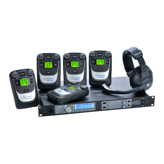
- Page 1 Tempest 2400 ® 2 -Channel Wireless Intercom Reference Manual...
- Page 3 Thank you from Clear-Com We at Clear-Com want to thank you for purchasing a Tempest®2400 Wireless Intercom System. We have made every effort to build a reliable, intuitive wireless intercom system that easily interfaces with your existing equipment, and provides the same functionality that you expect from your hard-wired intercom equipment.
- Page 4 850 Marina Village Parkway Alameda, CA 94501 U.S.A HME Clear-Com, Ltd. 7400 Beach Drive IQ Cambridge Cambridgeshire United Kingdom CB25 9TP ®Clear-Com and the Clear-Com logo are registered trademarks of HM Electronics, Inc. Tempest® is a registered trademark of CoachComm, LLC. Website: www.clearcom.com...
-
Page 5: Table Of Contents
Table of Contents Important Safety Instructions ........................1 A/C Power Warning ..........................2 Battery Safety ............................3 Battery Transportation ........................3 Battery Storage..........................3 Maintenance and Care ..........................4 Cleaning ............................4 Temperature and Humidity ......................4 Quick Start Guide ........................... 6 What You Will Need .......................... - Page 6 Accu-Sync ..............................39 Master Mode ............................40 Special RF Considerations with Multiple BaseStations ................41 Multi-System Tempest Technology ......................42 Maximum Number of Collocated Systems ..................43 BaseStation Controls ..........................44 Front Panel Left ............................44 1- Local Headset Connector ......................44 2- Talk Button and LED ........................44 3- Call Button ..........................
- Page 7 Battery Selection and Installation ......................55 Charging the Lithium-Polymer Battery ....................56 Power Options ..........................56 BeltStation Power On/Off ......................56 Pairing with a BaseStation ........................57 Pair BeltStation to BaseStation: ..................... 57 Adjust BeltStation Slot ........................57 Name Equipment ........................... 58 Personal Preferences ........................58 Call Function...........................
- Page 8 [This page intentionally left blank] www.clearcom.com...
-
Page 9: Important Safety Instructions
Clear-Com® Tempest®2400 2-Channel Wireless Intercom System... -
Page 10: A/C Power Warning
A/C Power Warning Users should exercise extreme care when working with electricity. Additional care should be used when working with electricity outdoors, in inclement weather. When working outdoors, or near water always connect the system into a ground-fault interrupting circuit. There are no user serviceable parts inside the Tempest BaseStation, Transceiver, or BeltStation. -
Page 11: Battery Safety
Do not expose batteries to excessive heat such as sunshine, fire or other heat sources. • CAUTION – Danger of explosion if battery is incorrectly replaced. Replace only with the same or equivalent type. • Properly dispose of used batteries promptly. • Keep away from children. Clear-Com® Tempest®2400 2-Channel Wireless Intercom System... -
Page 12: Maintenance And Care
Maintenance and Care Cleaning Generally, the Tempest Wireless hardware should be cleaned only with a damp cloth. A soft cloth with rubbing alcohol may be used to wipe the units, if more than water is needed. Never spray solvents or chemicals onto the units. Because of Tempest’s weather resistant design it is not highly susceptible to dust or airborne contaminants. - Page 13 [This page intentionally left blank] Clear-Com® Tempest®2400 2-Channel Wireless Intercom System...
-
Page 14: Quick Start Guide
Quick Start Guide What You Will Need BaseStation » Power cord » One BaseStation antenna » 1⁄8th inch male-to-male » Mini-stereo Pairing cable BeltStations - Up to 5 per BaseStation » Lithium-Polymer battery and » Charger - 1 per BeltStation Heads (customer supplied) »... - Page 15 Refer to the user manual for detailed instructions regarding: » Country limitation on 2.4GHz RF spectrum. » Adjusting the Network Number and Lockout Key. » Assigning names for equipment. » Charging batteries. Clear-Com® Tempest®2400 2-Channel Wireless Intercom System...
-
Page 16: Theory Of Operation
Theory of Operation Tempest uses Frequency Hopping Spread Spectrum (FHSS), Time Division Multiple Access (TDMA), and 2xTX technology. For example, on Frequency 1 the BaseStation and each BeltStation take turns broadcasting, each with its own time slot to send audio data (TDMA). The total time for one cycle is 5 milliseconds (1/200 second). - Page 17 Tempest offers a host of features and technology to ensure that it performs well in almost all production environments virtually anywhere in the world with no licensing requirements or fees. Clear-Com® Tempest®2400 2-Channel Wireless Intercom System...
-
Page 18: What's In The Box
What’s In The Box BaseStation BaseStation AC Power Cord (1) Whip Antenna ½ Wave Pairing Cable USB-A to USB-B Cable Documentation CD Quick Start Guide BeltStation BeltStation Lithium-Polymer Rechargeable Battery Battery Charger/Power Supply USB-A to Mini-USB Cable Remote Transceiver Remote Transceiver CAT-5 Cable for BaseStation Connection - 15 Feet (2) Whip Antenna ½... -
Page 19: Other Items You May Need
If you plan to connect the Tempest BaseStation to external 2-Wire party-line intercom systems, you will need to provide the appropriate 3-PIN XLR cabling. RJ-45 Connector Cable for 4-Wire If you plan to connect the Tempest BaseStation to external Clear-Com 4-Wire intercom systems, you will need to provide the appropriate cabling. RJ-45 to RJ-12 Adapter If you plan to connect to an RTS 4W system you will need adapters. -
Page 20: Basestation
BaseStation Steps to Setup the BaseStation • Choose a location for the BaseStation • Choose an antenna location and configuration • Maximize performance • Configure operation features » Set Band » Set Network Number and Lockout Key » Set Static or Dynamic Display »... -
Page 21: Power Connections
Local Area Network, the DHCP settings (IP address, MAC address, etc) will then display until MENU is pressed to escape or until the normal timeout is completed. The system will then display the main Operation screen and will be ready for normal use. Clear-Com® Tempest®2400 2-Channel Wireless Intercom System... -
Page 22: Antenna Location
Antenna Location 24” Proper antenna location is essential for the best system performance and maximum range. Antenna positioning is important with all RF systems and in all applications. Locate the Tempest BaseStation antenna as high as possible for your application to maximize line-of-sight RF operation. -
Page 23: Antenna Configurations
(1 RU) and use an optional LMR-195, a 50 ohm coax up to 10 ft to mount the antenna above the equipment rack. (5 ft of LMR-195 coax induces about 1 dB of attenuation.) Clear-Com® Tempest®2400 2-Channel Wireless Intercom System... -
Page 24: Maximizing System Performance And Operational Range
To remotely locate antenna always use high quality, low loss, 50 Ohm RF cable terminated with an RP-TNC connector for the BaseStation side connection and the appropriate antenna mating connector on the other end. LMR-195 (or equivalent) coaxial cables can satisfactorily be used in lengths up to 10 feet. LMR-400 coaxial cables (or equivalent) can be used at lengths up to 25 feet. -
Page 25: Configure The Basestation
This action produces the same result as scrolling with the Volume control to the desired menu item and pressing ENT or the Volume control. To view and select additional menu items, rotate the scroll knob and press ENT to select. Clear-Com® Tempest®2400 2-Channel Wireless Intercom System... -
Page 26: Adjust Sidetone
Adjust Sidetone To demonstrate the use of the controls, this details instructions to adjust the “Sidetone” for the front panel headset connector: 1. Press MENU to enter Menu Mode 2. Rotate the Volume knob and scroll to “BaseStation Settings” on the display. 3. -
Page 27: Selecting A Frequency Band
Band Start Width 2400 2480 None 2400 2450 2423 2473 2431 2480 1, 2, 2400 2428 7, 8, 9, 10, 11 2423 2450 1, 11 2453 2480 1, 2, 3, 4, 5, 6, 7 Clear-Com® Tempest®2400 2-Channel Wireless Intercom System... -
Page 28: Network Number And Lockout Key
Network Number and Lockout Key The Network Number determines the RF frequency hopping pattern for the BaseStation and its BeltStations. This is a key operational parameter and is represented by a number between 0 and 63. The Lockout Key prevents systems with the same Network Number from trying to communicate with each other and is represented by a number between 0 and 255. -
Page 29: Set Display Mode To Static Or Dynamic
Settings,” then “Name BeltStation.” Use the Volume control and the ENT button to select and change characters. Press ENT to save the changes. BeltStation names can be changed wirelessly from the BaseStation’s menu or from T-Desk when the system is on a local area network. Clear-Com® Tempest®2400 2-Channel Wireless Intercom System... -
Page 30: Basestation Headset Connection And Controls
BaseStation Headset Connection and Controls The BaseStation headset connection is a functional user communication point, and may also be used for setup and troubleshooting. The Front Panel Headset can communicate on any one of the two intercom channels. Controls for this headset are located just to the right of the connector, and in the menu on the BaseStation Settings screen. -
Page 31: Front Panel Lock
“Stage Announce” menu screen, under “Wired Intercom Settings.” In addition, the Stage button may be configured to also control an additional relay assigned to the users BeltStation. See the GPO Relay section for more details. Clear-Com® Tempest®2400 2-Channel Wireless Intercom System... -
Page 32: Gpo Relay Contacts
GPO Relay Contacts Tempest Wireless provides six General Purpose Output (GPO) contact closures. These GPO contact closures can be used for interfacing with other external devices. The Stage Announce (SA) Relay and the five GPO Relays, one for each BeltSta- tion, are available through the DB-15 Relay Connector on the back of the Tempest BaseStation. -
Page 33: Reset Memory
This is a BaseStation feature only. Selecting this option will only reset the Frequency Band to “1”, the Network Number to “0”, and the Lockout Key to “255”. The BeltStation radio settings are determined by the BaseStation. Clear-Com® Tempest®2400 2-Channel Wireless Intercom System... -
Page 34: Default Settings
Default Settings BaseStation Defaults BeltStation Defaults Headset Sidetone: -18 dB Headset Sidetone: -18 dB Headset MIC gain: +6 dB / +22 dB Headset MIC gain: +6 dB / +22 dB • Electret: +6 dB • Electret: +6 dB • Dynamic: +22 dB •... -
Page 35: Modes Of Operation
Shared BeltStations are unable to provide telemetry to the BaseStation or T-Desk, thus no BeltStation settings can be adjusted from the BaseStation or T-Desk. » Volume of the BeltStation that is actively talking is dynamically reduced to minimize the effect of echo. Clear-Com® Tempest®2400 2-Channel Wireless Intercom System... -
Page 36: Split Mode
Split Mode In Split mode, users are operating in a combination of Normal and Shared mode. This mode offers the use of 4 BeltStations (per BaseStation) that utilize the standard anytime talk back capability and allows an unlimited number of “shared” BeltStations to listen and talk on the final slot. -
Page 37: Wired Intercom Interface To The Basestation
CHAN A has been set for no wired intercom connection – the LEDs are off. • CHAN B is set for Clear-Com 2-Wire intercom connection. The upper slide switch is in the middle position and the 2-Wire LED aligned with CHAN B is illuminated. -
Page 38: Controls
The 2-Wire Intercom Type Select Switch determines the type of 2-Wire intercom that may be connected to the corresponding 2-Wire connectors on the rear panel of the BaseStation. Clear-Com, RTS, or BAL (AudioCom) can be selected. These switches only affect 2-Wire operation and do not control 4-Wire operation. -
Page 39: Steps To Configure A 4-Wire Intercom Connection
A standard CAT-5 patch cable can be used to connect between the matrix and the Tempest system. Tempest 4-Wire / RJ-45 Connecti on Pin # No Connecti on No Connecti on Audio Output (+) Audio Input (+) Audio Input(-) Audio Output (-) No Connecti on No Connecti on Clear-Com® Tempest®2400 2 -Channel Wireless Intercom System... -
Page 40: 2-Wire (Party-Line) Interface
Steps to Configure a 2-Wire Intercom Connection • Adjust the Intercom Type Slide Switches to appropriate manufacturer compatible setting- RTS, Clear-Com, Bal. • Select 2-Wire connection for the appropriate channels. -
Page 41: Auto-Null Explained
Brief louder active audio can help accelerate efficiency. If multiple BaseStations are connected by 2-Wire intercom connections, each BaseStation must be nulled separately. Null one BaseStation at a time. Clear-Com® Tempest®2400 2-Channel Wireless Intercom System... -
Page 42: Manual Null
Manual Null Generally Auto-Null will adequately control the inherent echo caused by the 2-wire hybrid circuitry. However, “Manual Null” is available if there is residual echo. If echo persist after testing for at least thirty seconds: 1. Turn off all TALK buttons on wireless and wired equipment. Since Tempest analyzes a tone to adjust the Null characteristics, any sounds entering through the wired or wireless systems will interfere with the nulling process. -
Page 43: 2-Wire Wiring Schemes
A and RTS channel 2 is place on channel B. Note for 2-Wire Clear-Com and Balanced (Audiocom) Users: For Clear-Com and Balanced 2-Wire intercoms, use the A and B male or female 3-pin (XLR-3M/F) connectors on the rear panel to connect up to two intercom channels. The male and female connectors for each channel are loop-through connections and are the same point electrically. -
Page 44: Connecting Multiple Basestations
Connecting Multiple BaseStations Tempest BaseStations may be used together to form large wireless systems, and may include external wired intercom systems. Intercom audio for any or all channels can be linked across multiple BaseStations. Audio from one BaseStation can be passed via a 2-Wire connection to another BaseStation if they are to share a single channel of audio. -
Page 45: Steps To Configure A Multiple Basestation System
Master Mode settings are found at the “Set Base as Master” screen under the “Multi-Base Settings” of the Main Menu. Once one BaseStation is in Master Mode, audio will be shared among all BaseStations that are connected to that intercom channel. Lines must be nulled for proper operation. Clear-Com® Tempest®2400 2-Channel Wireless Intercom System... -
Page 46: When An External 2-Wire Hardwired Intercom System Is Present
When an external 2-Wire hardwired intercom system IS present: Set the 2-Wire Intercom Type Select Switch to the proper type and select 2-Wire mode. Connect the hardwired intercom to the BaseStation. In this configuration each connected Tempest BaseStation intercom channel will receive power and termination from the wired intercom system. -
Page 47: Accu-Sync
The BaseSync cable is a DB-9F To DB-9M wired straight through on pins 1-5. The maximum distance a BaseSync cable can be is 1,500 feet (457.2 m). Never connect Accu-Sync cables between 2.4GHZ and 900MHz Tempest models. BASESYNC IN Accu-Sync - DB-9 Connector Clear-Com® Tempest®2400 2-Channel Wireless Intercom System... -
Page 48: Master Mode
Master Mode only works as Clear-Com type. If “RTS” or “BAL” is selected, an attempt to set the BaseStation as master will result in an error message. If the slide switch is changed from Clear-Com to RTS or BAL, Master Mode will turn off, and it will be necessary to return to the “Multi-Base Setting”... -
Page 49: Special Rf Considerations With Multiple Basestations
When two or more Tempest BaseStations are to be operated in the same location, connecting the BaseStations via the Accu-Sync connector on the back of the BaseStation can significantly increase system performance and operational range. Clear-Com® Tempest®2400 2-Channel Wireless Intercom System... -
Page 50: Multi-System Tempest Technology
Multi-System Tempest Technology Tempest is a digital, frequency hopping spread spectrum (FHSS) radio device. Using 80 MHz of spectrum in the 2.4GHz ISM frequency band, Tempest changes frequency (hops) 200 times per second, following one of 64 hopping patterns (Tempest Network Numbers 0 –... -
Page 51: Maximum Number Of Collocated Systems
Mode), may be collocated with minimal or no user perceived impact on system range or performance. The addition of one or more adverse conditions will limit the number, effectiveness and range of collocated systems in any given environment proportionally to the extent of the adverse condition(s). Clear-Com® Tempest®2400 2-Channel Wireless Intercom System... -
Page 52: Basestation Controls
BaseStation Controls Front Panel Left 1- Local Headset Connector The 4-PIN XLR male headset connector is compatible with most Dynamic or Electret headsets that have 4-PIN XLR female connectors. This headset connector allows a user to communicate on any one of the two intercom channels. Controls for this connector are located to the immediate right. -
Page 53: 7- Volume Control
WBP-1 and 2 are listening and talking on channel A, while also listening on channel D. WBP-3 is utilizing the Stage Announce feature and has the Battery Alert turned off. WBP-4 is listening on channels B and C. Clear-Com® Tempest®2400 2-Channel Wireless Intercom System... -
Page 54: Front Panel Right
The 2-Wire Intercom Type slide switch configure the BaseStation for the type of intercom that will be connected to the corresponding 2-Wire connectors on the rear panel of the BaseStation. Clear-Com, RTS, or BAL (AudioCom) can be selected. This switch only affects 2-Wire operation and not 4-Wire operation. The A/B switch selects the 2-Wire system type for both the A and the B intercom channels. -
Page 55: 5- 2-Wire/4-Wire Leds
LCD for approximately three seconds when done. Always power cycle the BeltStation after pairing. 10- Power ON/OFF Switch The ON/OFF switch is used to turn the BaseStation power (AC or DC) on and off. Clear-Com® Tempest®2400 2-Channel Wireless Intercom System... -
Page 56: Rear Panel Left
The Intercom Channel connectors (A/B) allow the user to connect the Tempest BaseStation to 2-Wire external intercom systems or other Tempest BaseStations. The XLR-3M/F 2-Wire intercom connectors interface with Clear-Com, RTS, Balanced and other compatible intercom systems. The pairs of XLR3-M and XLR-3F are electrically identical. -
Page 57: Rear Panel Right
RF interference. Any BaseStation that has a BaseSync OUT connection but does not have a BaseSync IN connection will generate a sync signal for connected BaseStations. Clear-Com® Tempest®2400 2-Channel Wireless Intercom System... -
Page 58: 6- Local Area Network (Lan) Rj-45 Connector
6- Local Area Network (LAN) RJ-45 Connector The Local Area Network (LAN) RJ-45 Connector is used to connect the Tempest BaseStation to a user supplied PC running Tempest Desktop Configuration (T-Desk) software. The user can then monitor and/or adjust BaseStation and BeltStation settings via the PC interface. -
Page 59: Basestation Menu
BaseStation Menu Clear-Com® Tempest®2400 2-Channel Wireless Intercom System... -
Page 60: Remote Transceiver
Remote Transceiver Setup the Transceiver • Choose a BaseStation location. • Choose a Transceiver location. • Choose an antenna configuration. • Install CAT-5 cable and connect to the BaseStation and Transceiver. • Confirm operation by observing the Transceiver LEDs. The Tempest Remote Transceiver is an optional accessory that allows antennas to be located up to 1,500 feet away from the BaseStation without the RF signal loss that is associated with using long runs of coaxial cable. -
Page 61: Transceiver Controls
Two Threaded Mounting Holes are provided on the back of the Remote Transceiver for use with the mounting bracket to mount the Transceiver in a convenient location. The mounting holes are #8-32 thread and accept a #8-32 x 3/8” pan head screw. Clear-Com® Tempest®2400 2-Channel Wireless Intercom System... -
Page 62: Beltstation
BeltStation The BeltStation can be configured in three ways. It can be configured by the BeltStation menu, wirelessly by the BaseStation menu, or using the PC interface called T-Desk. While many functions are available through all three methods, certain features are only available through the BeltStation. See T-Desk manual for details on configuring by PC. Configure the BeltStation by the BeltStation Menu Using a combination of controls and Menu settings you can set a variety of levels and options directly from the BeltStation controls. -
Page 63: Steps To Setup The Beltstations
Please be careful to insert alkaline AA batteries according to the marked polarity. All of the alkaline AA cells must be oriented the same direction. If the battery cover does not close properly, the battery may not be inserted correctly. Clear-Com® Tempest®2400 2-Channel Wireless Intercom System... -
Page 64: Charging The Lithium-Polymer Battery
Charging the Lithium-Polymer Battery With the Lithium-Polymer batteries installed in the battery compartment, plug the AC end of the supplied 5VDC Charger/Power Supply into a standard AC wall outlet. Open the rubberized access cover on the side of the BeltStation and plug the USB end of the Charger/Power Supply into the USB connector. -
Page 65: Pairing With A Basestation
“X”, making it easy to see at a glance, which BeltStations are currently active. A Multiple BaseStation system that uses iSelect Roaming must choose to use “Dynamic” slots to ensure that BeltStations can move from BaseStation to BaseStation when roaming. Clear-Com® Tempest®2400 2-Channel Wireless Intercom System... -
Page 66: Name Equipment
Name Equipment Name the BaseStation with a descriptive name which will appear on the BeltStation LCD display. This is most helpful when iSelect Roaming will be used to roam between BaseStation coverage areas. The BaseStation name can include up to 14 characters. -
Page 67: Set Mic Gain
Wireless ISO is enabled by default and is available only on channel A . It is activated by pressing and holding ENTER. ENTER enables the headset mic regardless of the “TALK A” button. Wireless ISO only operates in Operational mode. It does not operate in Menu mode. Clear-Com® Tempest®2400 2-Channel Wireless Intercom System... -
Page 68: Beltstation Overview
BeltStation Overview 1- Volume- CH A and CH B In Operational Mode turning the Volume control adjusts the volume of the audio. Volume indicators appear on the display during adjustment and are expressed in Decibels (dB). The Volume control has an option to be set to “Volume Press” where it requires a “press and turn”... -
Page 69: 1- Rubberized Access Cover
If they are using dynamic mics, they should short the input to ground. If they are using electret mics they should open the circuit. This will keep the belt from switching back and forth between modes. Clear-Com® Tempest®2400 2-Channel Wireless Intercom System... -
Page 70: Talk Button A And B
Talk Button A and B There are two TALK buttons on each BeltStation, one for channel A and the other for channel B. The Talk button enables the microphone signal for the assigned intercom channels. Tempest uses an intelligent latching method for TALK buttons. -
Page 71: Beltstation Menu
BeltStation Menu Clear-Com® Tempest®2400 2-Channel Wireless Intercom System... -
Page 72: How Do I
How Do I …? Remove Batteries from BeltStations Remove the battery cover from the back of the BeltStation by pressing lightly on the thumb grooves and sliding towards the bottom. Hold the BeltStation in one hand with the battery compartment facing downward over the open palm of your other hand. -
Page 73: Adjust Min/Max Beltstation Volume Levels
Select “Stage Announce”, select “S/A Audio”; select Momentary . • Press MENU to go up one level in the menu. • Select “Stage Announce;” to set “SA Relay” select SA Relay Enable . • The STAGE button is always Momentary when enabled. Clear-Com® Tempest®2400 2-Channel Wireless Intercom System... -
Page 74: Configure Relays For Individual Beltstations
Configure Relays for Individual BeltStations From the BeltStation: • Press MENU; select “Set Controls;” select “Select Relay.” Note that there are more options under “Set Controls” than fit on the screen. Scroll to the bottom of the screen and scroll one more detent too see the “Select Relay” option. -
Page 75: Update The Firmware (With Codeupdater)
Note: The PIC firmware version is only applicable to the BaseStation firmware. • If an update is available check the box under “Upgrade Selection” and click the <Upgrade> button. • Repeat these steps as needed for each Tempest unit. Clear-Com® Tempest®2400 2-Channel Wireless Intercom System... -
Page 76: Troubleshooting
Troubleshooting BaseStation Limited RF range BaseStation antenna or transceiver should be located as high as possible. Locating the BaseStation antenna above head level is critical for optimizing performance and range. • Confirm that BaseStation antenna or transceiver are in an appropriate location and orientation. •... - Page 77 Select 2-Wire for the relevant channels. Set only one of the Tempest BaseStations to Master Mode. Audio can only be passed from one BaseStation to another in the “Clear-Com mode” unless actually connected to to another type of wired intercom system. Connecting any wired intercom to any BaseStation will automatically disable Master Mode and disconnect all shared channels that do not have a wired intercom connected.
-
Page 78: Beltstation
BeltStation BeltStation will not power up • Confirm that battery(ies) is (are) installed correctly. • When using a Lithium-Polymer rechargeable battery, ensure that the battery is fully charged. • When using alkaline AA batteries ensure that batteries are fresh and are all facing the same way. Note the illustration in the battery compartment section. -
Page 79: Tempest Remote Transceiver
If there are BeltStations communicating to the BaseStation through the Remote Transceiver the RX LED should light as well. To manually re-initialize the Transceiver, power off the BaseStation for at least 15 seconds and power the BaseStation back on, with the Transceiver connected. Clear-Com® Tempest®2400 2-Channel Wireless Intercom System... - Page 80 [This page intentionally left blank] www.clearcom.com...
-
Page 81: Tempest Part Numbers
RJ45 Ethernet cable 15 foot in length CX-WB-CAB15 00001390 USB A to USB B cable 6 foot length CX-PRGM-CAB 1/8” to 1/8” stereo mini pairing cable 6 foot in length 00000637 Tempest® BeltStation battery cover Clear-Com® Tempest®2400 2-Channel Wireless Intercom System... -
Page 82: System Features
Talk switches can be de-latched via the Mic Kill feature from either the BaseStation or the hardwire intercom • Auxiliary audio input and output • LAN control interface • Electret or Dynamic Mic auto select • Multiple antenna connection options • Compatible with Clear-Com®, RTS®, Telex®, and other 2-Wire and 4-Wire intercom systems www.clearcom.com... -
Page 83: 2.4 Ghz System Specifications
FCC Part 15.247 and ETS 300.328 rules, license free Transmission Range 1,000 feet under ideal conditions (500 ft to 900 ft typical) Audio Dynamic Range >94dB Audio Frequency Response 300Hz–3.8KHz with proprietary audio voice shaping System Latency Less than 50ms direct Clear-Com® Tempest®2400 2-Channel Wireless Intercom System... -
Page 84: Basestation Specifications
BaseStation Specifications Intercom Audio Channels Full Duplex BeltStations per BaseStation Half-Duplex, Shared BeltStations per Base Unlimited Number of Antenna Ports per BaseStation Antenna Connector Type RP TNC Number of Synchronized BaseStations Maximum Range of BaseSync Cable 1,500 ft (457.2 m) BaseStation/BeltStation Pairing Via supplied Mini-jack/cable Programming Port... -
Page 85: Beltstation Specifications
Supplied Antenna Whip antenna, 2 each Dimensions with Antennas (inches) H 12” x W 3.7” x D 1.7” Weight 11 oz Operating Environment -20° to 50° C (-4° to 122° F); 10% to 90% Humidity Clear-Com® Tempest®2400 2-Channel Wireless Intercom System... - Page 86 [This page intentionally left blank] www.clearcom.com...
-
Page 87: Glossary
Dual Listen: This BeltStation feature permits an operator to simultaneously listen to two channels. Frequency Hopping, Spread Spectrum (FHSS): Radio technology that utilizes many frequencies in quick succession, intended to minimize the probability of radio frequency interference. Clear-Com® Tempest®2400 2-Channel Wireless Intercom System... - Page 88 Full Duplex: Simultaneous two-way conversations (i.e. telephone communication). GPIO: General Purpose Input Output – a simple device control method. Half Duplex: Two-way conversations, one-way at a time, such that one person cannot interrupt the other (i.e. walkie-talkie). IFB: Interrupted Feedback, or Interrupted Fold-Back - The IFB system connects control room personnel such as the director, or producer with the performers or “talent”.
- Page 89 Tempest Remote Transceiver: An accessory used with the Tempest BaseStati on to locate the antennas apart from the BaseStati on without RF signal loss or att enuati on. USB Connecti ons: USB-B USB-A USB-A Mini-USB-B Mini-USB-B Clear-Com® Tempest®2400 2 -Channel Wireless Intercom System...
-
Page 90: Limited Warranty
Limited Warranty This document details the Clear-Com Standard Limited Warranty for all new products for sale within all regions with the exception of Military, Aerospace, and Government (MAG). EXCEPT AS SET FORTH HEREIN (“LIMITED WARRANTY”), CLEAR-COM MAKES NO OTHER WARRANTIES, EXPRESS, IMPLIED OR STATUTORY, INCLUDING WITHOUT LIMITATION ANY WARRANTIES OF MERCHANTABILITY, NONINFRINGEMENT OF THIRD PARTY RIGHTS, OR FITNESS FOR A PARTICULAR PURPOSE, ALL OF WHICH ARE EXPRESSLY DISCLAIMED. - Page 91 Customer will pay Clear-Com’s then current published charges to restore such Covered Products to a condition eligible for further service under this Agreement. Clear-Com shall be excused from and shall not be liable for any failure or delay in performance under this Agreement due to the foregoing or any causes beyond its reasonable control.
-
Page 92: Technical Support & Repair Policy
Email: CustomerServicesAPAC@clearcom.com Email Technical Support is available for all Clear-Com branded products free of charge for the life of the product, or two years after a product has been classified as obsolete, whichever comes first. Support for Distributor and Dealer Sales Distributors and Dealers may utilize the Customer Service Centers once a system has been installed and commissioned. - Page 93 Advance Warranty Replacements (AWRs): During the first 30 days of the Standard Warranty Period: Once the equipment fault has been verified by Clear-Com or its authorized representative, Clear-Com will ship a new replacement product. The Customer will be provided with an RMA number and be required to return the faulty equipment within 14 days of receipt of the replacement or will be invoiced for the list price of a new product.
- Page 94 Customers requesting a non-warranty repair will be provided an estimate of the total repair cost prior to the return of the equipment. In the event that Clear-Com is unable to estimate the cost of repair, the Customer may elect to return the product to the factory for an estimate.
-
Page 95: Fcc Information
D. To ensure compliance with FCC exposure limits, no person must come closer than 26 cm (ten inches) from either the standard 4” Rubber Whip Antenna, the optional Directional Corner Reflector Antenna, or other approved antenna whichever is used with the Tempest BaseStation. Clear-Com® Tempest®2400 2-Channel Wireless Intercom System... -
Page 96: Tempest Block Diagram
Tempest Block Diagram www.clearcom.com... - Page 97 Tempest Block Diagram continued Clear-Com® Tempest®2400 2-Channel Wireless Intercom System...
-
Page 98: Index
Index Block Diagram 10 Symbols Button - Mic Kill 49 2-Wire 37, 87 Button - Talk 49 2-Wire - Configure 37 3-Pin Wiring Scheme 40 4-Wire 36 Call Button 49 5-Bay Battery 72 BaseStation - Call Button 49 Call Function 30 Call Function - BaseStation 65 A/C 1 Charging 63... - Page 99 Station - Naming 28 Talk Button 49 Tempest Part Numbers 79 Transceiver Controls 59 Transceiver - Setup 58 Transceiver - Using 74 Trouble Shooting 75 Warranty 84 Wired Intercom Interface 34 Wireless ISO 67 Clear-Com® Tempest®2400 2-Channel Wireless Intercom System...
- Page 100 [This page intentionally left blank] www.clearcom.com...
- Page 101 [This page intentionally left blank] Clear-Com® Tempest®2400 2-Channel Wireless Intercom System...
- Page 102 www.clearcom.com...
Need help?
Do you have a question about the Tempest2400 and is the answer not in the manual?
Questions and answers