
Related Manuals for RTI RP-1


Summary of Contents for RTI RP-1
- Page 1 RP-1 Operation & Installation Guide v1.0 Model RP-1 Remote Control Processor RF DATA STATUS...
- Page 2 FEDERAL COMMUNICATIONS COMMISSION NOTICE This equipment has been tested and found to comply with the limits for a Class B digital device, pursuant to Part 15 of the FCC Rules. These limits are designed to provide reasonable protection against harmful interference in a residential installation. This equipment generates, uses, and can radiate radio frequency energy and, if not installed and used in accordance with the instructions, may cause harmful interference to radio...
-
Page 3: Safety Suggestions
RP-1 Remote Control Processor SAFETY SUGGESTIONS Read Instructions. Read all safety and operating instructions before operating the unit. Retain Instructions. Keep the safety and operating instructions for future reference. Heed Warnings. Adhere to all warnings on the unit and in the operating instructions. - Page 4 RP-1 Remote Control Processor The power supply cord or the plug has been damaged. Objects have fallen or liquid has been spilled into the unit. The unit has been exposed to rain. The unit does not appear to operate normally or exhibits a marked change in performance.
-
Page 5: Limited Warranty And Disclaimer
RP-1 Remote Control Processor LIMITED WARRANTY AND DISCLAIMER Remote Technologies Incorporated warrants its products for a period of one (1) year from the date of purchase from Remote Technologies Incorporated or an authorized Remote Technologies Incorporated distributor. This warranty may be enforced by the original purchaser and... - Page 6 Remote Technologies Incorporated’s liability for any defective product is limited to repair or replacement of the product, at our option. If your RP-1 Processor needs service, please contact Remote Technologies Incorporated by telephone, fax or E-mail for return information. Please do not return products to Remote Technologies Incorporated without return authorization.
- Page 7 RP-1 Remote Control Processor...
-
Page 8: Table Of Contents
ENSE NPUT ...........9 ONNECTING THE NTENNA CHAPTER 4. OPERATION..........11 RF D LED ..............11 LED ..............11 TATUS RP-1 ............ 12 ROGRAMMING THE ............ 12 ETTING THE CHAPTER 5. TROUBLESHOOTING........13 RP-1 D ........13 UNCTION ROPERLY ....14... - Page 9 RP-1 Remote Control Processor CHAPTER 6. SERVICE AND SUPPORT ......15 RTI ............. 15 ONTACTING RTI T ............ 15 ECHNICAL UPPORT RP-1 .......... 17 HIPMENT OF ERVICE CHAPTER 7. SPECIFICATIONS ........19 APPENDIX A. MOUNTING HOLE PATTERN ..... 21 viii...
-
Page 10: Chapter 1. Welcome
It interfaces with a system’s equipment by using a single IR output port. In addition, the RP-1 is able to provide system power on/off status. All of the system’s control commands and programming (macros) are stored in non-volatile Flash memory within the RP-1. -
Page 11: Product Contents
RP-1 Remote Control Processor • Use only the power supply that is provided with the RP-1. Using the wrong type of power supply may result in permanent damage. • Do not disassemble the unit. Service and repair should be performed by an authorized technician only. -
Page 12: Chapter 2. Introduction
Chapter 2. Introduction FEATURES The RP-1 provides superior quality and reliability as well as these specific features: • One high output IR port for control up to 1000 feet away. • Output port is compatible with industry standard IR emitters and repeater systems. The output port incorporates both short-circuit and overload protection. -
Page 13: Reference
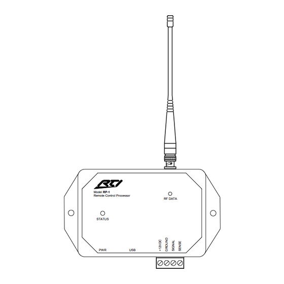
RP-1 Remote Control Processor RP-1 REFERENCE Antenna Connector RF Signal & Valid Data LED Bi-Color Status LED Model RP-1 Remote Control Processor RF DATA STATUS Power Jack USB Programming Removable Header Port for Connection to IR Repeater Systems and Voltage Power Status... -
Page 14: Connection Options
RF DATA STATUS RP-1 Power Supply To +12VDC trigger output, wall transformer The RP-1 output can power up connected to a switched to ten IR emitters directly outlet, current sensor, etc. (More than ten emitters requires an amplified connecting block) -
Page 15: Removable Header Terminal Description
Positive power supply connection. This is internally tied to the Power jack. This can be +12VDC used to power the RP-1 over a long distance if an AC wall outlet is not available near by. Common ground connection. Use this ground reference for... -
Page 16: Chapter 3. Installation
Chapter 3. Installation INSTALLATION LOCATION For best results install the RP-1 at least three (3) feet away from video monitors and other sources of strong electro- magnetic energy. 3 Feet 3 Feet Model RP-1 Remote Control Processor RF DATA STATUS... -
Page 17: Mounting
The RP-1 can be mounted on either a shelf or a wall (see Appendix A for mounting hole details). Since the IR output can drive up to 1000 feet of wire, the RP-1 does not need to be mounted near the equipment being controlled. -
Page 18: Connecting The Antenna
3VDC – 20VDC. The OFF state sense voltage is 0VDC - 2VDC. CONNECTING THE ANTENNA Connect the included antenna directly to the BNC connector on the RP-1. Do not attempt to locate the antenna away from the RP-1, or connect multiple antennas to the RP-1. - Page 19 RP-1 Remote Control Processor...
-
Page 20: Chapter 4. Operation
STATUS LED The status LED will illuminate Green if a valid system trigger code is detected. The LED will stay on while the RP-1 is busy processing the action associated with the trigger code. The status LED will flicker Green if an invalid system trigger code is detected. -
Page 21: Programming The Rp-1
Unless you implement some of the software’s advanced features, programming a system that uses an RP-1 is just as easy as programming one that doesn’t. SETTING THE ZONE CODE If the RP-1 is installed in close proximity to others, the system Zone Code can be changed in the TheaterTouch Designer™... -
Page 22: Chapter 5. Troubleshooting
RP-1 DOES NOT FUNCTION PROPERLY Verify that the USB cable is removed from either the RP-1 or the PC. The RP-1 will not function normally while there is an active USB connection with a PC. Verify the RP-1 is receiving a valid signal. The RF DATA LED should flash green when a valid signal is present. -
Page 23: Power Sense Input Does Not Function Properly
Windows. Make sure you are using the programming cable that was supplied by RTI and that both ends are connected securely. Make sure the PC detects the presence of the T2+. If it doesn’t, unplug the USB cable, wait for about ten... -
Page 24: Chapter 6. Service And Support
Tel. (952) 253-3100 Fax (952) 253-3131 info@rticorp.com RTI TECHNICAL SUPPORT At RTI, customer service and satisfaction is an utmost priority. If you are encountering any problems or have a question about your RTI product, please contact RTI Technical Support for assistance. - Page 25 For technical support or assistance with your RP-1, software, or accessories, contact RTI at: (952) 253-3137 support@rticorp.com www.rticorp.com/support For questions regarding service or repair of your RP-1, contact RTI at: (952) 253-3136 service@rticorp.com www.rticorp.com/service Please do not return products to RTI without return...
-
Page 26: Shipment Of Rp-1 For Service
If it is necessary to ship the RP-1 Remote Control Processor for service: ♦ Please pack it securely (we suggest that it be insured). - Page 27 RP-1 Remote Control Processor...
-
Page 28: Chapter 7. Specifications
Chapter 7. Specifications Power Supply: +12VDC , 500mA Number of Output Ports: One (1) High Power IR port IR Output Drive: 200mA maximum Infrared Transmission Bandwidth: 15kHz - 460kHz Power Sense Input: Off = 0VDC – 2VDC On = 3VDC – 20VDC Mounting: Wall-Mount or Free Standing... - Page 29 RP-1 Remote Control Processor...
-
Page 30: Appendix A. Mounting Hole Pattern
Appendix A. Mounting Hole Pattern Model RP-1 Remote Control Processor RF DATA STATUS 5.0 in (127mm) - Page 31 RP-1 Remote Control Processor...
- Page 32 ® It’s Under Control R e m o t e T e c h n o l o g i e s I n c o r p o r a t e d R e m o t e T e c h n o l o g i e s I n c o r p o r a t e d R e m o t e T e c h n o l o g i e s I n c o r p o r a t e d R e m o t e T e c h n o l o g i e s I n c o r p o r a t e d 7651 Anagram Drive...
Need help?
Do you have a question about the RP-1 and is the answer not in the manual?
Questions and answers