Advertisement
Available languages
Available languages
Quick Links
High color.Wide screen. User-friendly
DOP-108IG
Delta Electronics, Inc.
No.18, Xinglong Rd., Taoyuan City
33068, Taiwan
Instruction Sheet
(1) General precautions
Thank you for purchasing this product. This DOP-108IG instruction sheet provides information for the
DOP-108IG series HMI. Before using this product, please read through this instruction sheet carefully to
ensure the correct use of the product. Please keep this sheet handy for quick reference whenever needed.
Before finishing reading this sheet, please follow the instructions below:
Install the product in an indoor location, which is free of vapor and corrosive and inflammable gas.
Please refer to the wiring diagram when connecting the wires.
Ensure this product is correctly grounded. The grounding method must comply with the national
electrical standard guidelines (refer to NFPA 70: National Electrical Code, 2005 Ed.).
Do not disassemble the HMI or change the wiring when power is on.
Do not touch the power supply when power is on, or it may cause electric shock.
When the HMI displays a low power notification and requires a battery change, please contact
your local distributor or Delta Customer Service Center for the replacement. Do not change the
batteries by yourself.
This product can be used with other industrial automation equipment. Please read through this
sheet carefully and install the product according to the instructions to avoid danger.
Cleaning method: please use a dry cloth to clean the product.
This product must be used at an altitude below 2,000 m (6561.68 ft).
If the equipment is used in a manner not specified by the manufacturer, the protection provided by
the equipment may be impaired.
For repair and maintenance, please contact Delta Electronics, Inc. Address: No.18, Xinglong Rd.,
Taoyuan City, Taiwan. TEL: +886-3-3626301.
If you have any inquiry during operation, please contact our local distributors or Delta Customer Service
Center. The instruction sheet may be revised without prior notice. Contact our distributors or download the
latest version from the Delta website (http://www.deltaww.com.tw/ia).
(2) Communication port pin assignment
DOP-108IG COM1
COM Port
Pin
1
2
3
4
5
6
7
8
9
Note: the mark "-" means connection is not required.
DOP-108IG COM2
MODE1
MODE2
COM Port
Pin
RS-232
RS-422
1
-
TXD+
2
RXD
-
3
TXD
-
4
-
RXD+
5
GND
GND
6
-
TXD-
7
RTS
-
8
CTS
-
9
-
RXD-
Note:
1. The mark "-" means connection is not required.
2. To use COM2 for flow control through RS-232 (RTS and CTS signals), COM3 port is not operable.
DOP-108IG COM3
COM Port
Note:
1. The mark "-" means connection is not required.
DOP-108IG Ethernet interface (LAN)
Ethernet interface
Note: the mark "-" means connection is not required.
(3) Description of each part
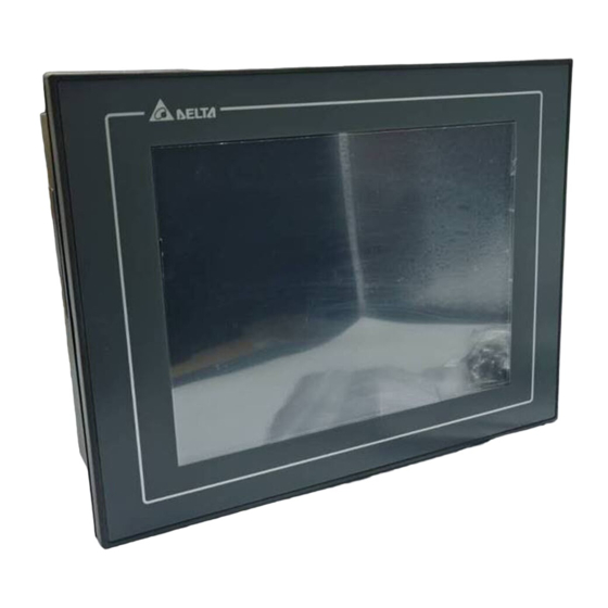
DOP-108IG (front view)
MODE1
RS-232
-
RXD
TXD
-
DOP-108IG (rear view)
GND
-
RTS
CTS
-
MODE3
RS-485
D+
-
-
-
GND
D-
-
-
-
A
Power input connector
B
COM3 (supports communication indicator)
C
COM2 (supports communication indicator
D
COM1
E
Memory card slot / battery cover
MODE1
MODE2
MODE3
Pin
RS-232
RS-422
RS-485
1
-
TXD+
D+
2
RXD
-
-
3
TXD
-
-
4
-
RXD+
-
5
GND
GND
GND
6
-
TXD-
D-
7
-
-
-
8
-
-
-
9
-
RXD-
-
Contact
Pin
Ethernet
1
TX+
2
TX-
3
RX+
4
-
5
-
6
RX-
7
-
8
-
A
Operation / display area
F
Audio output interface
G
USB Host
)
H
Ethernet interface (LAN)
I
USB Slave
-
-
(4) Mounting dimensions
DOP-108IG
(5) Installation and wiring
Precautions:
Mount the HMI according to the illustration below. Incorrect installation direction may result in
malfunction.
To ensure the HMI is well ventilated, make sure there is sufficient space between the HMI and the
adjacent objects or walls.
This product should be installed in a case or on a platform which conforms to enclosure Type 4X
standard (for indoor use only).
The maximum panel thickness for mounting must be no greater than 5 mm (0.2 inches).
Please use copper wires.
Installation diagram:
Step 1:
Step 2:
Put the waterproof gasket onto the HMI and then
Place the fasteners into the slots and tighten
insert the HMI into the panel cutout.
the screws until reaching the panel cutouts.
Step 3:
Step 4:
Tighten the screws with the torque between
For heat dissipation, please keep a
0.5 N-M and 0.7 N-M to avoid damage to the
minimum clearance of 60 mm (2.36 inches)
plastic case.
and 45 mm (1.77 inches) respectively on the
DOP-108IG torque: 6.17 lb-inch (0.7 N-M)
rear and bottom of the HMI.
Unit: mm (inches)
Advertisement

Related Manuals for Delta DOP-108IG Series


Summary of Contents for Delta DOP-108IG Series
- Page 1 Thank you for purchasing this product. This DOP-108IG instruction sheet provides information for the Ethernet DOP-108IG series HMI. Before using this product, please read through this instruction sheet carefully to ensure the correct use of the product. Please keep this sheet handy for quick reference whenever needed.
-
Page 2: Hardware Specifications
5. For the programming software DOPSoft of DOP-100 series and its user manual, you can download them at (6) Hardware specifications http://www.delta.com.tw/ia. 6. DOP-100 series can be used with other industrial automation equipment. Please read through this sheet carefully Model DOP-108IG and install the product according to the instructions to avoid danger. - Page 3 Ürünün kullanımı ile ilgili sorularınız için teknik servisimizle iletişime geçebilirsiniz. Bu bilgi dokümanının içeriği herhangi bir bildirime gerek duyulmadan değiştirilebilir. Dokümanın son versiyonunu internetten Adım 1: Adım 2: indirebilirsiniz. http://www.delta.com.tw/ia. HMI içine su geçirmez contanın takıldığına emin Montaj aparatlarını HMI’ın yuvalarına olunuz ve sonra pano boşluğuna yerleştiriniz.
- Page 4 İzoleli güç kaynağı kullanılması tavsiye edilir. DOP-100 serisi ürünlerin program editörü olan DOPSoft programı ve kullanıcı manuel’i web sayfamızdan indirilebilirsiniz. http://www.delta.com.tw/ia. DOP-100 serisi endüstriyel otomasyon donanımı olarak kullanılabilir. Tehlikeleri önlemek için bu bilgi dokümanını dikkatlice okuyun ve belirtilen direktiflere göre kurulumu gerçekleştirin.
- Page 5 MODE2 MODE3 COM Port 示意圖 腳位 DOP-108IG RS-232 RS-422 RS-485 TXD+ RXD+ 高彩‧寬螢幕‧友善人機介面 DOP-108IG TXD- Delta Electronics Inc, No.18, Xinglong Rd., Taoyuan City RXD- 33068, Taiwan 註: 安裝說明 1. ”-“表示不需連接。 (1) ⼀般注意事項 DOP-108IG 網路埠定義 感謝您使用本產品,本人機介面安裝說明書提供 DOP-108IG 系列人機介面的相關資訊。在使用之前,請 說明 網路埠示意圖 腳位...
- Page 6 為 25 ° C (77°F)常溫常濕工作環境下之預估值。 2. 隔離電路耐受規格:可承受 1 分鐘 1500 V 高壓突波。 3. 消耗功率為無外接週邊設備時,人機本體所消耗的功率。建議選用的電源供應器容量為標示消耗功率之 1.5 ~ 2 倍, 以確保人機運作正常。 4. 建議使用隔離式電源供應器。 5. DOP-100 系列編輯軟體 DOPSoft 系列及其使用操作手冊,可由台達網站下載取得, (6) 硬體規格 網址為 http://www.delta.com.tw/ia。 6. DOP-100 系列適用於工業自動化設備,請詳細閱讀此說明,並依指示安裝以避免發生危險。 型號 DOP-108IG 面板種類 8” TFT LCD (65536 色) 解析度...
- Page 7 为了使冷却循环效果良好, 安装人机接口时, 其上下左右与相邻的物品和挡板(墙)必须保持足够的空间, 若使用本设备时未遵循制造商所订定之规格,将导致本设备所提供的保护功能受损。 否则会造成散热不良。 维修请联络: 台达电子工业股份有限公司,台湾桃园市兴隆路 18 号,TEL: 03-3626301。 使用于 Type 4X 室内用等级之外壳平面。 如果您在使用上仍有问题,请洽询经销商或者本公司客服中心。由于产品精益求精,当内容规格有所修正 安装面板最大板厚请勿超过過 5 mm (0.2 inches)。 时,请洽询代理商或至台达网站(http://www.delta.com.tw/ia)下载最新版本。 请用铜制导线。 (2) 通讯脚位定义 安装示意图: 步骤⼀: 步骤二: DOP-108IG COM1 定义 请确实将防水垫圈装入,然后再安装人机接口。 请确实将固定片螺丝组装入内,然后下方钩住 MODE1 COM Port 示意图...
- Page 8 2. 隔离电路耐受规格:可承受 1 分钟 1500 V 高压突波。 3. 消耗功率为无外接外围设备时,人机本体所消耗的功率。建议选用的电源供应器容量为标示消耗功率之 1.5 ~ 2 倍,以确保人机工作正常。 4. 建议使用隔离式电源供应器。 (6) 硬件规格 5. DOP-100 系列编辑软件 DOPSoft 系列及其使用操作手册,可由台达网站下载取得,网址为 型号 DOP-108IG http://www.delta.com.tw/ia。 面板种类 8”TFT LCD(65536 色) 6. DOP-100 系列适用于工业自动化设备,请详细阅读此说明,并依指示安装避免产生危险。 分辨率 800 x 600 pixels 显 示 有毒物质 -Hazardous Substances C 下半衰期>1 万小时)...
Need help?
Do you have a question about the DOP-108IG Series and is the answer not in the manual?
Questions and answers